1
SUGGESTIONS ON THE CONTROL
PANEL INSTALLATION
•
•
•
•
•
The installation must be done by specialized technicians, in compliance with the local, national and European
regulations in force (UNI 8612) as well as to the instructions quoted on this manual. The installer must verify the
type of system and if necessary connect security devices (differential and magnetothermic switches) which comply
with the current regulations. The manufacturer declines any responsibility for damages to people or things caused
by wrong installations, improper and unreasonale usages,tampering as well as by non observance of the current
regulations.
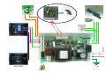
Protect the control board with a 6A automatic switch or with a 16A monophase switch and fuses. Make sure that
the ground wire (terminal 1) is properly connected to the ground dispenser of the system. It is necessary to respect
the phase and neutral polarity in the 230V a.c. power supply line (terminal 3= phase, terminal 2= neutral). The
minimum section required for the power circuits (motors and blinker outputs) is 1,5 mmq. Always use separated
connection for auxiliary and control (inputs) power ciurcuits in order to avoid interferences or damages caused by
unduced tensions (do not use only one multipolar wire). In case of lines longer than 50 mt it is advisable to
dismatch the control circuits with some relays in the control board. If the n.c. inputs (limitswitches, photocells, stop
button) are not used they have to be connected to the common (terminal 15) through jumpers.
After installing all the security and electrical devices (buttons, photocells, blinkers, etc.) and having done all the
electrical connections, power up the control unit and check the following:
Remember that the inputs which are not used have to be jumpered. If led DL1 (red) is not on, check that the 230V
a.c. power tension arrives to the terminal 2 and 3, also control the fuses integrity and if necessary replace them
with others of the same capacity.
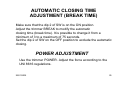
After starting the motors make sure that they can be stopped with a force no higher than 150N (
about 15 Kg) according to the UNI 8612 regulations. If necessary, adjust the force through the POWER
trimmer.
25/01/2005
15