1
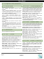
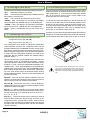
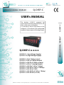
eed
eed
quality electronic design
ANALOG SIGNAL DISPLAY
www.qeed.it
[email protected]
www.dem-it.com
Q-DISP-C
Q-DISP-C-x-x-x-x
Q-DISP-C-L (Low Voltage Supply)
Q-DISP-C-H (High Voltage Supply)
ANALOG SIGNAL DISPLAY
The displays Q-DISP-C, prepared for
mounting on the back panel, 96x48mm, will
allow you to count and totalize.
It is possible to have a high power or low
voltage AC / DC and have up to configurable
outputs of relay outputs and analog outputs
Q-DISP-C
USER’s MANUAL
Q-DISP-C-x-R (n°1 Relay output)
Q-DISP-C-x-R-R (n°2 Relays output)
Q-DISP-C-x-R-R-R (n°3 Relays output)
Q-DISP-C-x-AO (n°1 Analog Output)
Q-DISP-C-x-AO-R (n°1 AO, n°1 Relay)
Q-DISP-C-x-AO-R-R (n°1AO, n°2 Relays)
Q-DISP-C-x-AO-AO (n°2 AO)
Q-DISP-C-x-AO-AO-R (n°2 AO, n°1 Relay)
Q-DISP-C-x-AO-AO-AO (n°3 AO)
Sept 2013
DEM SPA - Z.I. Villanova, 20 -32013 Longarone (BL) Italy - tel. +39 0437 761021 -fax +39 0437 760024 - P.Iva 00691730253
User’s Manual
1. Meter Q-DISP-C
Panel meter 96x48mm counter, ratemeter, periodmeter
Panel meter configurable as impulse counter, ratemeter and
periodmeter. Accepts wide range of signal types such as
Push-pull, NPN, PNP, Namur, TTL, inductive, mechanical,
... also monodirectional and bidirectional encoder signals
(quadrature signals).
Highly configurable, with pull-up/pull-down resistors, trigger
levels, pulse detection on raising or falling edge, excitation
voltage and antirrebound filters. ‘Trigger Sense’ utility for easy
trigger level adjustment.
Scalable reading by configurable multiplier and divider factors (1 to 999999). Configurable decimal point position.
Resolution 6 digits (999999/-199999).
Excitation voltage configurable to 5V, 9V, 15V and 18V.
Up to 3 relay outputs controlled from the instrument alarms,
can be increased to 6 relay outputs (with simplified functionality, see section 2). Configurable direct access to setpoint
values modification on key UP (5).
Standard 96x48mm DIN size. Universal AC and DC power
options. Up to three control and/or signal retransmission
modules. IP54 front protection, with optional IP65.
Connections via plug-in screw terminals and configuration via
three front push-buttons. For industrial applications.
Counter modes
Counter functionality allows to choose between 5 counting
modes (simple counter, quadrature counter, counter with
inhibit control, differential counter and counter with add/substract control). Instrument has two impulse input channels
(A and B) and selectable ascending or descending counting
modes.
Alarm functions with ‘reset to zero’ or ‘return to preset’ create
a continuous counting cycle (instrument cycles from ‘preset
value’ to ‘alarm value’). Instrument provides a internal cycle
counter, accessible to the operator.
Memory retention in case of power loss or deactivation. When
power is back again, instrument recovers the last reading
and configuration.
Maximum counting frequency is 250 KHz in ‘FAST’ mode.
Ratemeter mode
Ratemeter function allows to choose between normal ratemeter (one single input channel) or bidirectional ratemeter
(quadrature ratemeter) with detection of clockwise / counterclockwise sense of turn.
In ratemeter mode, the instrument counts the number of
impulses during a fixed period of time, and calculates the
frequency.
For low frequency applications, a special ‘SLOW’ mode is
available, which offers the fastest response time for low frequency applications. See section 1.13 for more information.
Recursive filter ‘Average’ to stabilize unstable readings.
Maximum frequency in ratemeter mode is 900KHz and
minimum frequency (with ‘SLOW’ mode activated) is 0.001
Hz (1mHz).
Periodmeter mode
Periodmeter mode detects the signal time between impulses.
For long period applications, a special ‘SLOW’ mode is available which offers the fastest response time for low frequency
applications. See section 1.13 for more information.
Reset function is accessible from rear terminal and front
push-button. The front reset can be enabled or disabled. Configurable preset value. Alarm activation can be associated
to an action : ‘reset to zero’, ‘return to preset’ or ‘no action’.
Relays activation and deactivation times are independent
and configurable.
1.1 Order reference
Model
Q-DISP -
C
Power
-
H
-H
-L
Page 2
(85-265 Vac/dc)
(11-60 Vdc
and 24/48 Vac)
Option1
-
---
Option2
-
---
Option3
-
---
-R (1 relay)
-R (1 relay)
-R (1 relay)
-AO (Analogue output) -AO (Analogue output) -AO (Analogue output)
-
(empty)
-
(empty)
-
(empty)
Q-DISP-C
User’s Manual
Index
1. Meter Q-DISP-C . . . . . . . . . . . . . . . . . . . 2
1.1 Order reference . . . . . . . . . . . . . . . . . . 2
1.2 Start-up . . . . . . . . . . . . . . . . . . . . . . 3
1.3 Front view . . . . . . . . . . . . . . . . . . . . . 4
1.4 Power connections . . . . . . . . . . . . . . . . 4
1.5 Sensor configuration and connections . . . . . . 4
1.6 Rear view . . . . . . . . . . . . . . . . . . . . . 4
1.7 Signal connections . . . . . . . . . . . . . . . . 4
1.8 Technical data . . . . . . . . . . . . . . . . . . . 5
1.8 Technical data (cont.) . . . . . . . . . . . . . . . 5
1.9 Mechanical dimensions (mm) . . . . . . . . . . . 5
1.10 Configuration menu . . . . . . . . . . . . . . . 6
1.10 Configuration menu (cont.) . . . . . . . . . . . . 7
1.10.1 Menu Cnf.1 - Counter . . . . . . . . . . . . . 8
1.10.2 Menu Cnf.2 - Counter quadrature . . . . . . . . . . 8
1.10.3 Menu Cnf.3 - Counter + Inhibit . . . . . . . . . . . . 8
1.10.4 Menu Cnf.4 - Counter add/substract . . . . . . . . 8
1.10.5 Menu Cnf.5 - Counter differential . . . . . . . . . . 8
1.10.6 Menu Cnf.6 - Ratemeter . . . . . . . . . . . . 8
1.10.7 Menu Cnf.7 - Ratemeter quadrature . . . . . . . . . 9
1.10.8 Menu Cnf.8 - Periodmeter . . . . . . . . . . . 9
1.11 Default factory configuration . . . . . . . . . . . 9
1.12 Configuration menu descriptions . . . . . . . . 10
1.12.1 Function mode . . . . . . . . . . . . . . . . 10
1.12.2 Decimal point . . . . . . . . . . . . . . . . 10
1.12.3 “cnF.1” - Counter . . . . . . . . . . . . . . 10
1.12.4 “cnF.2” - Counter quadrature . . . . . . . . 10
1.12.5 “cnF.3” - Counter + Inhibit . . . . . . . . . . 10
1.12.6 “cnF.4” - Counter + Control A/S . . . . . . . . 10
1.12.7 “cnF.5” - Counter differential . . . . . . . . . 11
1.12.8 “cnF.6” - Ratemeter . . . . . . . . . . . . . . 11
1.12.9 “cnF.7” - Ratemeter quadrature . . . . . . . . 11
1.12.10 “cnF.8” - Periodmeter . . . . . . . . . . . . 11
1.12.11 Menu Sensor . . . . . . . . . . . . . . . . 12
1.12.12 Menu Alarms . . . . . . . . . . . . . . . . 12
1.12.13 Menu Tools . . . . . . . . . . . . . . . . . 13
1.12.14 Menu OptX - Options . . . . . . . . . . . . 13
1.13 Mode ‘SLOW’ . . . . . . . . . . . . . . . . . . 13
1.14 Mode ‘FAST’ . . . . . . . . . . . . . . . . . . 13
1.15 ‘Trigger Sense’ . . . . . . . . . . . . . . . . . 13
1.16 Messages and errors . . . . . . . . . . . . . . 14
1.17 Operating the menus . . . . . . . . . . . . . . 14
1.18 Accessing the instrument . . . . . . . . . . . . 14
1.19 Warranty . . . . . . . . . . . . . . . . . . . . 15
1.20 Installation precautions . . . . . . . . . . . . . 15
2. Control modules . . . . . . . . . . . . . . . . . . . 15
2.1 Module R . . . . . . . . . . . . . . . . . . . . . 15
2.2 Module AO . . . . . . . . . . . . . . . . . . . . 15
1.2 Start-up
To start-up the instrument, take the following steps into consideration :
4. Select the function mode (counter, ratemeter, periodmeter,
...) and values for multiplier and divider (menu “Func”).
1. Input signal connections à see section 1.5 y 1.7
4.1. function mode
à
see section 1.12.1
2. Power connections
4.2. decimal point position “dP”
à
see section 1.12.2
à see section 1.4
3. Sensor configuration àsee section 1.12.11 (menu
“SnSr”). Select from the “Auto” menu entry one of the listed
sensors, to configure the default values for that sensor
(values indicated in Table1 (see section 1.5)). Values can
also be manually configured :
3.1. pull-up/pull-down resistors on channel A, B and Reset
3.2. trigger level (shared for channels A and B). (Trigger
level for reset is fixed at 2,5V).
4.3. multipliers and dividers à
see sections 1.12.3
to 1.12.10 (menu “cnF.X”) depending on the function mode
selected.
5. Advanced configuration
To modify setpoint values, presets, activation edges, etc ...
see next sections in this document.
3.3. antirrebound filter (shared for channels A and B)
3.4. excitation voltage value
Q-DISP-C
Page 3
User’s Manual
1.6 Rear view
1.3 Front view
Alarms
Option3
Option1
Option2
Units
Logo
123 45
Button ‘LE’
Button ‘UP’
Button ‘SQ’
Front reset for Quick access
counter mode
Signal
Access to
‘Configuration menu’
1.4 Power connections
Earth connection - Although a terminal is
offered for earth connection, the connection is optional. The instrument does not
need this connection for correct functioning nor for compliance with the security
regulations.
Power
1.7 Signal connections
8 9 0
1 2 3 4 5
Fuse - To comply with security regulation
61010-1, add to the power line a protection
fuse acting as disconnection element, easily accessible to the operator and identified
as a protection device.
~
+
~
-
Reset
Channel B
Channel A
Power “H” fuse 250mA time-lag
Vexc
Power “L” fuse 400mA time-lag
0V
1.5 Sensor configuration and connections
Examples of connections and
configurations for different sensor types.
Connections are indicated for
channel A. For channel B connect the same way, but in channel B.
Note - values indicated on Table1
are usual values. Confirm with
your sensor datasheet the specifications that apply and adapt the
configuration values and connections as needed.
Connections
(for channel A)
Sensor
Mechanical
contact
Namur
0V Channel A
Channel A Vexc
Antirrebound
Trigger
filter
Pulls
Vexc
Pull-up
No
100mSec.
2,5V
Pull-down
9V
No
3,0V
NPN 2 wires
0V Channel A
Pull-up
18V
No
2,5V
NPN 3 wires
0V Channel A Vexc
Pull-up
18V
No
2,5V
PNP 2 wires
0V Channel A
Pull-down
18V
No
2,5V
PNP 3 wires
0V Channel A Vexc
Pull-down
18V
No
2,5V
Push-pull
0V Channel A Vexc
No
18V
No
2,5V
TTL
CMOS
Pick-up
0V Channel A
No
5V
No
2,5V
AC <30V
Inductive
0V Channel A
No
No
No
0V
Table1 - Configuration and connections for different sensor types
Examples for channel A connections
Page 4
Q-DISP-C
User’s Manual
1.8 Technical data
Digits
Type
Height
Display maximum
Display minimum Decimal point
Overrange Underrange
1.8 Technical data (cont.)
6
7 segments, red
14 mm
999999
-199999
selectable 8.8.8.8.8.8.
configurable ‘flash’, ‘reset’, ‘preset’
configurable ‘flash’, ‘reset’, ‘preset’
Signals accepted
Connections
Signal types
impulses and frequencies
2 wires, 3 wires and quadrature
Push-pull, NPN, PNP, Namur,
Pick-up, TTL, inductive, mechanical, quadrature, ...
Maximum Vdc at input ±30Vdc
Input impedance
2K4 if pull resistors on
470K if pull resistors off
Maximum and minimum frequencies
Counter
with ‘FAST’ mode
max. 250 KHz
without ‘FAST’ mode max.
9 KHz
Counter quadrature x1 max. 17 KHz
Counter quadrature x2 max. 16 KHz
Counter quadrature x4 max. 11 KHz
Counter + inhibit max.
9 KHz
Counter + control A/S
max.
9 KHz
Counter differential
max.
9 KHz
Ratemeter
with ‘SLOW’ mode
with ‘SLOW’ mode
Ratemeter quadrature x1
Ratemeter quadrature x2
Ratemeter quadrature x4
max. 900 KHz
max. 200Hz
min.
1mHz
max. 17 KHz
max. 16 KHz
max. 11 KHz
Periodmeter
with ‘SLOW’ mode
with ‘SLOW’ mode
max. 900 KHz
max. 200 Hz
min.
1mHz(1000 seconds)
Accuracy
Of the quartz oscillator
Thermal drift
±0.01%
20ppm/ºC
Excitation voltage
Configurable to
Current
Protection
5V, 9V, 15V, 18V
70mA max.
yes, current limited to 70mA max.
Refresh
Display refresh
Number of readings
Number of readings
15 / second
100 / second in counter modes
1 / GATE in rate and period modes
Power
Power “H”
Power “L”
Consumption
Isolation
(tested 60 seconds)
3500Veff for power “H”
2000Veff for power “L”
Configuration
3 frontal push buttons
(rear jumper for coupling selection)
Functions available
Multiplier and divider
yes, configurable
Preset
yes, configurable
Edge selection
yes, configurable
‘SLOW’ frequency mode yes, configurable
Recursive filter
yes, configurable
Pull resistors
yes, configurable
Trigger levels
yes, configurable
Excitation voltage
yes, configurable
Antirrebound filter
yes, configurable
Memory
yes, maximum ,minimum, cycles
Memory of counter
yes, recovers data on power loss
Reset configurable
yes, front and/or rear reset and/or
assigned to setpoint
Zeros to the left
yes, configurable
Password
yes, configurable
Brightness control
yes, 5 levels
Optional boards
maximum 3 (see section 2)
Mechanical
Mounting
Connections
Weight
Housing materials Front size
Panel cut-out
Deep from panel
panel
plug-in screw terminals
<150 grams
ABS, polycarbonate
96x48mm
92x44mm
91mm (including terminal)
Protection IP54 standard
IP65 optional (Front sealed.
Opening the front breaks the seal)
Temperature Operation 0 to 50ºC
Temperature Storage
–20 to +70ºC
Warm-up 15 minutes
1.9 Mechanical dimensions (mm)
48
96
44
85 to 265 Vac/dc
11 to 60 Vdc and 24/48Vac
<4W
16
75
8
Panel
cut-out
92
Q-DISP-C
Page 5
User’s Manual
1.10 Configuration menu
Press ‘SQ’ button (<) to enter ‘Configuration Menu’
Explanation on each menu entry starts at section 1.13
No pull
Pulls - channel B
Counter
Function
Counter quadrature
Pull Up
Pull Down
Counter + inhibit
Counter + control add / substract
No pull
Pulls - reset
Counter differential
Ratemeter
Pull Up
Pull Down
Ratemeter quadrature
Periodmeter
Trigger
Press LE (3) to change selection
Decimal point
Configuration
Counter
or
or
...
or
Config. Counter
Config.
quadrature
Periodmeter
Menu shows only “cnF.x” for the selected function.
See sections 1.11.1 to 1.11.8 for an explanation on
each menu entry.
by rising edge
Activation
channel A
Mechanical contact
Sensor
Auto config.
Trigger level
(from 0.0Vdc to
3.9Vdc). See
section 1.15 for
‘Trigger Sensor’
utility.
by falling edge
by rising edge
Activation
reset
Namur
by falling edge
NPN 2 wires
NPN 3 wires
Excitation
voltage
PNP 2 wires
PNP 3 wires
Push pull
TTL
CMOS
Pick-up
Antirrebound
Antirrebound filter
(0 to 1000mSec.)
Inductive
Vac <30V
Alarms
Al. active
No pull
Pulls - channel A
Alarm1
Pull Up
Al. inactive
Al. as maximum
Pull Down
Page 6
Active
Alarm type
Q-DISP-C
Al. as minimum
User’s Manual
1.10 Configuration menu (cont.)
Setpoint
Setpoint2
Setpoint
Hysteresis
Hysteresis
Setpoint3
Delay0
Delay on relay
activation
(in seconds)
Delay1
Delay on relay
deactivation
(in seconds)
Front reset
Second setpoint
Counter
overrange
Flash
Setpoint2
To preset
Continue
On alarm
To zero
To zero
Flash
To preset
Counter
underrange
To zero
To preset
Menu for Alarm2
With left zeros
Menu for Alarm3
Left Zeros
Value
Tools
Memory of
maximum
Password
Max. memory reset
Value
Memory of
minimum
Factory
configuration
Min. memory reset
Without left zeros
Password
6 digits
Apply
Firmware version
Value
Memory of
cycles
Version
Cycle memory reset
Minimum
Brightness
Key UP
See Cycles
See Max.
Maximum
Menu for optional module at ‘Opt1’
Option1
Menu for optional module at ‘Opt2’
See Min.
Option2
Menu for optional module at ‘Opt3’
Setpoint1
Option3
Q-DISP-C
Page 7
User’s Manual
1.10.1 Menu Cnf.1 - Counter
Configuration
Counter
Multiplier
Divider
Preset
1.10.4 Menu Cnf.4 - Counter add/substract
Multiplier
1 to 999999
Divider
1 to 999999
Configuration
Counter + Control
add / substract
Multiplier
Divider
Preset value
-199999 to 999999
Preset
Up counter
Mode
‘FAST’ mode
Configuration
Counter
quadrature
Divider
Preset
Configuration
Counter
differential
Multiplier
1 to 999999
Divider
Divider
1 to 999999
Preset value
-199999 to 999999
Multiplier
Preset
Preset value
-199999 to 999999
Adds if channel B
is at ‘1’
Adds if channel B
is at ‘0’
2 imp. per cycle
4 imp. per cycle
Multiplier
1 to 999999
Divider
1 to 999999
Preset value
-199999 to 999999
1.10.6 Menu Cnf.6 - Ratemeter
1 imp. per cycle
Steps
Divider
1 to 999999
1.10.5 Menu Cnf.5 - Counter differential
1.10.2 Menu Cnf.2 - Counter quadrature
Multiplier
Control A/S
Down counter
Multiplier
1 to 999999
Configuration
Ratemeter
Multiplier
Divider
Multiplier
1 to 999999
Divider
1 to 999999
Seconds
Time gate
1.10.3 Menu Cnf.3 - Counter + Inhibit
Configuration
Counter
+ Inhibit
Multiplier
Divider
Preset
Multiplier
1 to 999999
Divider
1 to 999999
Preset value
-199999 to 999999
Up counter
Mode
Inhibit
Page 8
‘SLOW’ mode
max. wait time
1 to 1000 Sec.
Average
Filter value
from 0.0 to 99.9
Down counter
Active if channel
B is at ‘1’
Active if channel
B is at ‘0’
Q-DISP-C
User’s Manual
1.10.7 Menu Cnf.7 - Ratemeter quadrature
Configuration
Ratemeter
quadrature
Multiplier
Divider
Multiplier
1 to 999999
Function (“Func”)
Decimal point (“dP”)
counter (“cn.1”)
no
Divider
1 to 999999
Counter configuration (“cnF.1”)
Multiplier (“Mult”)
Divider (“dIV”)
Preset (“PrSt”)
Mode (“ModE”)
‘FAST’ (“FASt”)
x1
/1
0
up counter (“uP”)
off (“oFF”)
Sensor (“SnSr”)
Pull channel A (“PuL.A”)
Pull channel B (“PuL.b”)
Pull reset (“PuL.r”)
Trigger (“trIG”)
Activation channel A (“Act.A”)
Activation reset (“Act.r”)
Excitation voltage(“V.EXc”)
Antirrebound filter
no pull (“no”)
no pull (“no”)
pull-up (“P.uP”)
2,5Vdc
rising edge (“on_h”)
rising edge (“on_h”)
15Vdc
0 mSeconds
Seconds
Time gate
1 imp. per cycle
Steps
2 imp. per cycle
4 imp. per cycle
Average
Filter value
from 0.0 to 99.9
1.10.8 Menu Cnf.8 - Periodmeter
Configuration
Periodmeter
Multiplier
Divider
Multiplier
1 to 999999
Divider
1 to 999999
Seconds
Time gate
‘SLOW’ mode
Average
1.11 Default factory configuration
Tools (“tooL”)
Memory of maximum
Memory of minimum
Memory of cycles
Key UP (“K.uP”)
Cycles
Maximum
Minimum
Alarm1 setpoint
Alarm2 setpoint
Alarm3 setpoint
Front reset (“F.rSt”)
Counter overrange
Counter underrange
Left zeros
Password
Brightness
Alarms 1,2 and 3
Active
Type
Setpoint
Hysteresis
Activation delay (“dEL.0”)
Deactivation delay (“dEL.1”)
Setpoint2
On Alarm
max. wait time
1 to 1000 Sec.
Filter value
from 0.0 to 99.9
-199999
999999
0
Off
Off
Off
Off
Off
Off
On
Flash (“FLSh”)
Flash (“FLSh”)
Off
Off
3
Off (disabled)
maximum alarm
1000
0 counts
0.0 seconds
0.0 seconds
Off
continue
Ratemeter (“cnF.6”) and Periodmeter (“cnF.8”) configuration
Multiplier (“Mult”)
x1
Divider (“dIV”)
/1
Time gate (“GAtE”)
0.5 seconds
‘SLOW’ mode (“SLoW”)
Off
Recursive filter (“AVr”)
Off
Q-DISP-C
Page 9
User’s Manual
1.12 Configuration menu descriptions
1.12.1 Function mode
1.12.4 “cnF.2” - Counter quadrature
Select de function of the instrument.
“cn.1” - Counter - Input impulses on channel A. Channel
B disabled.
“cnq.2” - Counter for quadrature signals - Input impulses
in quadrature (bidirectional encoder) on channels A and B.
“cnI.3” - Counter + inhibit control - Input impulses on channel A. Inhibition control inhibit on channel B.
“cnc.4” - Counter + control add / substract- Input impulses on channel A. Control for function add or substract,
on channel B.
“cnd.5” - Counter differential - Input impulses with add
function on channel A. Input impulses with substract function
on channel B.
“rt.6” - Ratemeter - Input impulses on channel A. Channel
B disabled.
“rtq.7” - Ratemeter for quadrature signals - Input impulses
in quadrature (bidirectional encoder) on channels A and B.
The “cnF.2” menu is visible only when function mode “cnq.2”
‘counter quadrature’ is selected. Impulses received are internally counted, multiplied by the “MuLt” parameter, divided
by the “dIV” parameter, and the result is updated on display.
Multiplier (“MuLt”) - Value from 1 to 999999. Multiplier factor
to be applied to the total number of impulses counted.
Divider (“dIV”) - Value from 1 to 999999. Divider factor to be
applied to the total number of impulses counted.
Preset (“PrSt”) - Value from 999999 to -199999. Reset
activation loads on display the preset value.
Edges (“q.124”) - Value “1--1”, “1--2” or “1--4”. Select “1-1” to count 1 impulse per quadrature cycle. Select “1--2” to
count 2 impulses per quadrature cycle. Select “1--4” to count
4 impulses per quadrature cycle.
1.12.5 “cnF.3” - Counter + Inhibit
“Prd.8” - Periodmeter - Input impulses on channel A. Channel B disabled.
The “cnF.3” menu is visible only when function mode “cnI.3”
‘counter + inhibit’ is selected. Impulses received are internally
counted, multiplied by the “MuLt” parameter, divided by the
“dIV” parameter, and the result is updated on display.
The selected function (“Func”) modifies the configuration
menu (“cnF.x”) presented by the instrument.
Multiplier (“MuLt”) - Value from 1 to 999999. Multiplier factor
to be applied to the total number of impulses counted.
1.12.2 Decimal point
Select the position for the decimal point. Modify with the LE
button and validate with the SQ button.
1.12.3 “cnF.1” - Counter
The “cnF.1” menu is visible only when function mode “cn.1”
‘counter’ is selected. Impulses received are internally counted, multiplied by the “MuLt” parameter, divided by the “dIV”
parameter, and the result is updated on display.
Multiplier (“MuLt”) - Value from 1 to 999999. Multiplier factor
to be applied to the total number of impulses counted.
Divider (“dIV”) - Value from 1 to 999999. Divider factor to be
applied to the total number of impulses counted.
Preset (“PrSt”) - Value from 999999 to -199999. Reset
activation loads on display the preset value.
Mode (“ModE”) - Value “uP” / “doWn”. Select “uP” for up
counter (received impulses add). Select “doWn” for down
counter (impulses received substract).
‘FAST’ mode (“FASt”) - Value “on” / “oFF”. See section 1.14
Divider (“dIV”) - Value from 1 to 999999. Divider factor to be
applied to the total number of impulses counted.
Preset (“PrSt”) - Value from 999999 to -199999. Reset
activation loads on display the preset value.
Mode (“ModE”) - Value “uP” / “doWn”. Select “uP” for up
counter (received impulses add). Select “doWn” for down
counter (impulses received substract).
Inhibit (“Inh”) - Value “on_h” / “on_0”. Select “on_h” to inhibit
counting when channel B is at logic state ‘1’. Select “on_0” to
inhibit counting when channel B is at logic state ‘0’.
1.12.6 “cnF.4” - Counter + Control A/S
The “cnF.4” menu is visible only when function mode “cnc.4”
‘counter + control add / substract’ is selected. Impulses
received are internally counted, multiplied by the “MuLt”
parameter, divided by the “dIV” parameter, and the result is
updated on display.
Multiplier (“MuLt”) - Value from 1 to 999999. Multiplier factor
to be applied to the total number of impulses counted.
Divider (“dIV”) - Value from 1 to 999999. Divider factor to be
applied to the total number of impulses counted.
Preset (“PrSt”) - Value from 999999 to -199999. Reset
activation loads on display the preset value.
Page 10
Q-DISP-C
User’s Manual
Control A/S (“Add”) - Value “on_h” / “on_0”. Select “on_h”
to add the impulses received on channel A when channel
B is at logic state ‘1’ (impulses received on channel A are
substracted if channel B is at logic state ‘0’). Select “on_0”
to add the impulses received on channel A when channel
B is at logic state ‘0’ (impulses received on channel A are
substracted if channel B is at logic state ‘1’).
1.12.7 “cnF.5” - Counter differential
The “cnF.5” menu is visible only when function mode “cnd.5”
‘counter differential’ is selected. Impulses received are internally counted, multiplied by the “MuLt” parameter, divided by
the “dIV” parameter, and the result is updated on display. Impulses received on channel A always add. Impulses received
on channel B always substract.
Multiplier (“MuLt”) - Value from 1 to 999999. Multiplier factor
to be applied to the total number of impulses counted.
Divider (“dIV”) - Value from 1 to 999999. Divider factor to be
applied to the total number of impulses counted.
Preset (“PrSt”) - Value from 999999 to -199999. Reset
activation loads on display the preset value.
1.12.9 “cnF.7” - Ratemeter quadrature
The “cnF.7” menu is visible only when function mode “rtq.7”
‘ratemeter quadrature’ is selected. Based on the number of
impulses received during the time window defined at the
“GAtE” parameter, frequency is calculated (impulses received / ‘GATE’). The frequency value obtained is multiplied
by the “MuLt” parameter, divided by the “dIV” parameter, and
the result is updated on display. Value on display is updated
every X seconds (X value defined at the “GAtE” parameter).
Multiplier (“MuLt”) - Value from 1 to 999999. Multiplier factor
to be applied to the total number of impulses counted.
Divider (“dIV”) - Value from 1 to 999999. Divider factor to be
applied to the total number of impulses counted.
Time window (“GAtE”) - Selectable 0.5, 1.0, 2.0, 4.0, 8.0
and 16.0 seconds. Time window to count received impulses
and calculate the frequency.
Edges (“q.124”) - Value “1--1”, “1--2” o “1--4”. Select “1-1” to count 1 impulse per quadrature cycle. Select “1--2” to
count 2 impulses per quadrature cycle. Select “1--4” to count
4 impulses per quadrature cycle.
Average (AVR) - Value from “0.0” to “99.9”. Recursive filter.
The severity of the filter increases with the value selected.
1.12.8 “cnF.6” - Ratemeter
The “cnF.6” menu is visible only when function mode “rt.6”
‘ratemeter’ is selected. Based on the number of impulses
received during the time window defined at the “GAtE” parameter, frequency is calculated (impulses received / ‘GATE’).
The frequency value obtained is multiplied by the “MuLt”
parameter, divided by the “dIV” parameter, and the result
is updated on display. Value on display is updated every X
seconds (X value defined at the “GAtE” parameter).
Multiplier (“MuLt”) - Value from 1 to 999999. Multiplier factor
to be applied to the total number of impulses counted.
Divider (“dIV”) - Value from 1 to 999999. Divider factor to be
applied to the total number of impulses counted.
Time window (“GAtE”) - Selectable 0.5, 1.0, 2.0, 4.0, 8.0
and 16.0 seconds. Time window to count received impulses
and calculate the frequency. Inactive if ‘SLOW’ mode is active.
‘SLOW’ mode (“SLoW”) - Selectable “on” / “oFF”. Select
“on” to activate and define the value for parameter ‘Max. waiting time’ between 1 and 1000 seconds. See section 1.13 for
more information on ‘SLOW’ mode. ‘SLOW’ mode disables
the value selected at “GAtE”.
Average (AVR) - Value from “0.0” to “99.9”. Recursive filter.
The severity of the filter increases with the value selected.
1.12.10 “cnF.8” - Periodmeter
The “cnF.8” menu is visible only when function mode “Prd.8”
‘periodmeter’ is selected. Based on the number of impulses
received during the time window defined at the “GAtE” parameter, period is calculated (‘GATE’ / impulses received ). The
period value obtained is multiplied by the “MuLt” parameter,
divided by the “dIV” parameter, and the result is updated on
display. Value on display is updated every X seconds (X value
defined at the “GAtE” parameter).
Multiplier (“MuLt”) - Value from 1 to 999999. Multiplier factor
to be applied to the total number of impulses counted.
Divider (“dIV”) - Value from 1 to 999999. Divider factor to be
applied to the total number of impulses counted.
Time window (“GAtE”) - Selectable 0.5, 1.0, 2.0, 4.0, 8.0
and 16.0 seconds. Time window to count received impulses
and calculate the frequency. Inactive if ‘SLOW’ mode is active.
‘SLOW’ mode (“SLoW”) - Selectable “on” / “oFF”. Select
“on” to activate and define the value for parameter ‘Max. waiting time’ between 1 and 1000 seconds. See section 1.13 for
more information on ‘SLOW’ mode. ‘SLOW’ mode disables
the value selected at “GAtE”.
Average (AVR) - Value from “0.0” to “99.9”. Recursive filter.
The severity of the filter increases with the value selected.
Q-DISP-C
Page 11
User’s Manual
1.12.11 Menu Sensor
1.12.12 Menu Alarms
Configures the input channels to recognize impulses from
sensors connected on channels A, B and reset.
Automatic sensor configuration (“Auto”) - Select the type
of sensor to automatically configure sensor parameters as
shown on Table1 (section 1.5). Configured parameters are:
pull resistors, excitation voltage, antirrebound filter and trigger level. Parameters can be changed on each parameter
menu entry. The list of predefined sensors are : mechanical
contact (“MEch”), namur (“nAMr”), NPN 2 wires (“nPn.2”),
NPN 3 wires (“nPn.3”), PNP 2 wires (“PnP.2”), PNP 3 wires
(“PnP.3”), push-pull (“Ph.PL”), TTL (“ttL”), CMOS (“cMoS”),
pick-up (“Pk.uP”) inductive (“Ind”) and AC signals <30Vdc
(“Ac”).
Pulls on channel A (“PuL.A”) - Value “no”, “P.uP” o “P.dn”.
Select “P.uP” to activate the pull-up resistor on channel A.
Select “P.dn” to activate the pull-down resistor on channel
A. Select “no” to deactivate pulls on channel A. Trigger is
automatically set to 2,5V when “P.uP” or “P.dn” are selected.
Pulls on channel A (“PuL.b”) - See previous entry ‘Pulls
on channel A’.
Pulls del reset (“PuL.r”) - See previous entry ‘Pulls on
channel A’. Trigger value for reset channel is fixed at 2,5V.
Trigger (“trIG”) - Values from 0,0V to 3,9V. Select the trigger value. The input signal is considered to be a logical ‘1’
when the input signal value is higher than the trigger value
(in Vdc). The input signal is considered to be a logical ‘0’
when the input signal value is lower than the trigger value (in
Vdc). Trigger value is the same for channels A and B. Trigger
value for reset channel is fixed at 2,5V. See section 1.15 for
‘Trigger Sensor’ utility.
Activation for channel A (“Act.A”) - Value “on_h” / “on_0”.
Select “on_h” to enable detection of impulses on channel A
by rising edge. Select “on_0” to enable detection of impulses
on channel A by falling edge.
Activation for reset (“Act.r”) - Value “on_h” / “on_0”. Select
“on_h” to enable reset activation by rising edge. Select “on_0”
to enable reset activation by falling edge.
Excitation voltage (“V.Exc”) - Select value for excitation
voltage to power-up the transducer, between 5V, 9V, 15V and
18V. Select “no” to disable excitation voltage.
Configuration menu for 3 alarms that control relays R1 (see
section 2.1) installable at slots ‘Opt1’, ‘Opt2’ and ‘Opt3’. (Special modules R2, R4 and R6 allow for up to 6 simple relay
outputs. See section 2.3 for more information).
Active (“ACt”) - Value “on” / “oFF”. Defines if the instrument
has to manage this alarm or not. Select “oFF” for alarm not
managed.
Type (“tYPE”) - Value “MAX” / “MIn”. Defines the behavior
of the alarm as maximum or minimum alarm. The alarms
configured as maximum are activated when the display value
is equal or higher than the setpoint. The alarms configured
as maximum are deactivated when the display is lower than
the setpoint. The alarms configured as minimum have the
inverse behavior.
Setpoint (“SEt”) - Value from “999999” to “-199999”. Alarm
setpoint.
Hysteresis (“hYSt”) - Value from “0” to “999999”. Counts
of hysteresis. The hysteresis applies on the deactivation of
the alarm.
Delay 0 (“dEL.0”) - Value from “0.0” to “99.9” seconds. Activation delay for relays R1. Relays and front led are activated
X seconds after alarm activation.
Delay 1 (“dEL.1”) - Value from “0.0” to “99.9” seconds.
Deactivation delay for relays R1. Relays and front led are
deactivated X seconds after alarm deactivation.
Setpoint2 (“SEt2”) - Value from “-199999” to “999999”.
Second setpoint. The second setpoint allows for the creation
of activation windows. If the alarm is configured as maximum
with setpoint 1000 and setpoint2 is configured at 1500, the
alarm will be activated between 1000 and 1500 and the
alarm will be deactivated when display is <1000 and >1500.
Setpoint2 is affected on the same way as the setpoint with
hysteresis and delays.
On Alarm (“on.AL”) - Value “cont”,“to_0” or “to_p”. Behavior
when the display reaches the setpoint value. Applies only to
counter modes. Select “cont” to continue counting. Select
“to_0” to reset display to ‘0’. Select “to_p” to jump display to
preset value. Selection of “to_0” or “to_p”, configures “dEL.1”
by default to 1 second.
Antirrebound filter (“rbnd”) - Antirrebound filter. Selectable
from 0 to 1000 mSeconds. For mechanical contact sensors
set value at 100mSeconds. When an impulse is received,
the filter activates and no new impulses are counted for the
duration of the filter value. When the filter time is over, next
impulse received is counted and filter activates again.
Page 12
Q-DISP-C
User’s Manual
1.12.14 Menu OptX - Options
1.12.13 Menu Tools
Configuration of non usual parameters and special tools.
Maximum (“MAX”) - Maximum memory value and memory
reset function.
Minimum (“MIn”) - Minimum memory value and memory
reset function.
Cycles (“cYcL”) - Cycle memory value and memory reset
function.
Key UP (“K.uP”) - Configuration of information accessible
from key UP (5). Select “on” to activate desired entries.
Pressing key UP (while in normal working mode), will visualize each one of the parameters selected.
“cYcL” - Visualization of number of cycles
“MAX” - Visualization of memory of maximum
“MIn” - Visualization of memory of minimum
“ALr1” - Visualization and modification of setpoint1 value
“ALr2” - Visualization and modification of setpoint2 value
“ALr3” - Visualization and modification of setpoint3 value
Front reset (“F.rSt”) - Value“on” / “oFF”. Select “on” to activate reset when pressing front key LE (3). Select “oFF” to
disable front reset (pressing LE key will make no function).
Counter overrange (“c.orG”) - Defines the function to
activate in case of counter overrange (display is higher than
999999). Select “FLSh” to set display in flash mode. Select
“to_0” to reset display to ‘0’. Select “to_p” to jump display to
preset value.
Counter underrange (“c.urG”) - Defines the function to
activate in case of counter underrange (display is lower than
-199999). Select “FLSh” to set display in flash mode. Select
“to_0” to reset display to ‘0’. Select “to_p” to jump display to
preset value.
Left Zero (“LZEr”) - Value “On/Off”. Select “On” to visualize
zeros to the left.
Password (“PASS”) - Select a 6 digit number to act as
password. This password will be requested when entering
the ‘Configuration Menu’ (key SQ <). To deactivate the
password select “oFF”.
Factory configuration (“FAct”) - Factory default configuration. Select “yES” to activate the factory default configuration.
Menu entries “oPt1”, “oPt2” y “oPt3” give access to the configuration menus for the optional modules installed on slots
‘Opt1’, ‘Opt2’ y ‘Opt3’. This menu depends on the installed
option. If there is no option installed the instrument shows
“nonE”. Relay modules ‘R1’ are controlled from the standard
alarm menu (see section 1.12.12).
1.13 Mode ‘SLOW’
Optional mode available in Ratemeter (“rt.6”) and Periodmeter (“Prd.8”) modes. Activate the ‘SLOW’ mode enables
the fastest response time for low frequency applications. In
this mode, the frequency and period calculation is calculated
directly by measuring the time between two consecutive
impulses. The measure is updated each time a new impulse
is received.
The ‘SLOW’ mode needs the user to define the parameter
‘maximum waiting time’ between impulses (with a value between 1 and 1000 seconds). If the configured time is gone
with no impulses received, the frequency value is set to ‘0’
(period value is also set to ‘0’). Parameter ‘GAtE’ has no application in this mode.
The ‘SLOW’ mode is functional for frequencies below 200Hz.
1.14 Mode ‘FAST’
Optional mode available in Counter mode (“cn.1”). Activate
the ‘FAST’ mode enables a higher frequency input detection
rate on channel A, up to 250KHz, for simple counter “cn.1”
mode only.
The activation of ‘FAST’ mode has the following restrictions
: impulse detection edge is fixed to ‘raising edge’, and the
first edge (raising or falling edge) received after a power-up
(or configuration change) is not detected as impulse but will
be used for internal initialization.
1.15 ‘Trigger Sense’
The ‘Trigger Sense’ provides information on the input signal
state, while adjusting the trigger level. The ‘trigger’ menu (“<”
/ “SnSr” / “trIG”), displays the actual value of the trigger level
(in Vdc) and two leds to the left named ‘up’ led and ‘down’ led.
Led ‘up’
Version (“VEr”) - Firmware version installed..
Led ‘down’
Light (“LIGh”) - Brightness. Select between 5 predefined
levels of brightness.
Input signal at a ‘high level’ state is represented by the activation of the ‘up’ led. Input signal at a ‘low level’ state is
represented by the activation of the ‘down’ led.
For a correct trigger configuration, modify the trigger level until both ‘up’ and ‘down’ leds are being alternatively activated.
This alternative activation state indicates that the instrument
is correctly detecting the ‘1’ and ‘0’ input signal states.
Q-DISP-C
Page 13
User’s Manual
1.16 Messages and errors
1.18 Accessing the instrument
The instrument can display the following messages and errors.
“Err.1” Password entered is not correct.
“Err.2” The instrument has detected an installed option but
was unable to communicate.
“Err.8” The instrument is limiting the current at Vexc.
“999999”+ flash. The display is in overrange (real display
should be higher than 999999 and can not be displayed).
“-199999” + flash. The display is in underrange (real display
should be lower than -199999 and can not be displayed).
“E.101” Option is installed but the type can not be recognized.
1.17 Operating the menus
The instrument has two menus accessible to the user :
‘Configuration menu’ (key SQ) (<)
‘Quick access menu’ (key UP) (5)
You may need to access the inside of the instrument to insert
additional modules. Use a flat screwdriver to unlock the upper
clips marked with “A”. Then unlock the lower clips marked
with “B” and remove the front cover. Let the inside of the
instrument slide out of the housing.
To reinsert the instrument make sure that all modules are
correctly connected to the pins on the display module. Place
all the set into the housing, assuring that the modules correctly fit into the internal guiding slides of the housing. Once
introduced, place again the front cover by clipping first the
upper clips “A” and then the lower clips “B”.
Important - If your instrument was delivered with the IP65 front
seal option, accessing the inside of the instrument will permanently break the IP65 seal on the areas of clips “A” and “B”.
A
The ‘configuration menu’ allows to change the configuration
of the instrument. Access to the ‘configuration menu’ can be
protected enabling the ‘PASSWORD’ function. During operation with the ‘configuration menu’ the alarms are kept ‘on-hold’.
When leaving the ‘configuration menu’ the instrument performs
a restart, and new configuration is applied. On restart of the
instrument, also the optional modules are restarted (relays,
analogue outputs, ...).
The ‘quick access menu’ is a configurable menu where the user
can configure access to the following information : memory
values for maximum, minimum and cycles, and setpoint values
for alarms 1, 2 and 3. The list of configurable parameters is accessible at “tooL” / “k.uP”. Alarm setpoints can be modified when
enabled in the ‘quick access menu’. the ‘PASSWORD’ function
does not block access to the ‘quick access menu’. While working in the ‘quick access menu’ the instrument keeps working
as normal the background. There is no reset when leaving the
‘quick access menu’.
Rollback - After 30 seconds without interaction from the
operator, the instrument leaves the active menu and returns
normal working mode. All changes are discarded.
Key SQ (<) - Selects the menu entry currently displayed.
When entering a numeric value (for example a setpoint value)
validates the value on display.
Key UP (5) - Moves vertically on the menu entries. When
entering a numeric value (for example a setpoint value) modifies the current digit by increasing its value up from 0 to 1,
2, 3, 4, 5, 6, 7, 8, 9.
Key LE (3) - Leaves the current menu. Pressing LE several
times will leave all menus. When leaving all menus in the
configuration menu, changes will be saved . When entering
a numeric value (for example a setpoint value) it moves from
one digit to the next. Each digit value can then be modified
with the UP button.
Page 14
Q-DISP-C
B
Risk of electric shock. Removing the front cover will
grant access to the internal circuits. Disconnect the
input signal to prevent electric shock to the operator.
Operation must be performed by qualified personnel
only.
User’s Manual
1.19 Warranty
All instruments are warranted against all manufacturing
defects for a period of 24 MONTHS from the shipment date.
This warranty does not apply in case of misuse, accident or
manipulation by non-authorized personnel. In case of malfunction get in contact with your local provider to arrange for
repair. Within the warranty period and after examination by
the manufacturer, the unit will be repaired or substituted when
found to be defective. The scope of this warranty is limited to
the repair cost of the instrument, not being the manufacturer
eligible for responsibility on additional damages or costs. .
2. Control modules
2.1 Module R
Module with 1 relay. Up to a maximum of three R modules
can be installed in one Q-DISP panel meter.
Relay type
Maximum current
Voltage
Installable at
3 contacts (Common, NC, NO)
8A (resistive load)
250 Vac continuously
Option1 and/or Option2 and/or Option3
1.20 Installation precautions
Instrument protected with double isolation. No earth connection
required.
A B C
Opt 3
Risk of electrical shock. Instrument terminals can be connected
to dangerous voltage.
Instrument is in conformity with CE rules and regulations. See
“CE Declaration of Conformity” further in this document.
The instrument does not have a general switch and will start operation as
soon as power is connected. The instrument does not have protection fuse,
the fuse must be added during installation.
The instrument is designed to be panel mounted. An appropriate ventilation
of the instrument must be assured. Do not expose the instrument to excess
of humidity. Maintain clean by using a humid rag and do NOT use abrasive
products such as alcohols, solvents, etc.
Terminal A
Terminal B
Terminal C
Common
NO - Normally Open
NC - Normally Closed
Module with 1 analogue output. Configurable 4/20mA or
0/10Vdc. Output signal proportional to the reading. Scaling
through the frontal keypad. Up to a maximum of three AO
modules can be installed in one Q-ISP panel meter.
Output
Accuracy
Isolated
Thermal drift
Installable at
General recommendations for electrical installations apply, and for proper
functionality we recommend : if possible, install the instrument far from
electrical noise or magnetic field generators such as power relays, electrical motors, speed variators, ... If possible, do not install along the same
conduits power cables (power, motor controllers, electrovalves, ...) together
with signal and/or control cables.
Before proceeding to the power connection, verify that the voltage level
available matches the power levels indicated in the label on the instrument.
In case of fire, disconnect the instrument from the power line, fire alarm
according to local rules, disconnect the air conditioning, attack fire with
carbonic snow, never with water.
Q-DISP-C
4/20mA, 0/10Vdc selectable
0.1% FS
yes, 1000Vdc
50 ppm/ºC for Vdc
60 ppm/ºC for mA
Option1 and/or Option2 and/or Option3
Opt 1
MV A B C
MV A B C
Installation of this instrument must be performed by qualified personnel
only. This manual contains the appropriate information for the installation.
Using the instrument in ways not specified by the manufacturer may lead
to a reduction on the specified protection level. Disconnect the instrument
from power before starting any maintenance and / or installation action.
Opt 2
A B C
2.2 Module AO
Opt 3
This instrument has been designed and verified according to the 61010-1
CE security regulation, and is designed for applications on industrial environments. See the “CE Declaration of Conformity” further in this document for
information on the category of measure and the degree of pollution levels
that apply.
Opt 1
A B C
Opt 2
MV A B C
Jumper M
Jumper V
mode mA
mode Vdc
Terminal A
Terminal B
Terminal C
Vexc (+13.8Vdc @25mA)
Signal output (mA or Vdc)
GND
Page 15
w w w. q e e d. i t
i n fo @ qeed.i t
S a les d e p ar t m ent. . . . . . . . . . . . . sa l es@ qeed.it
Te ch n i cal d e p a r t m ent. . . . . . . tec hn ic a l @ qeed.it
Z.I. Villanova, 20 - 32013 Longarone (BL), I taly
Ph. +39 0437 761021
Fax +39 0437 760024
September 2013