1
User’s Manual
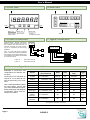
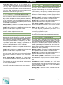
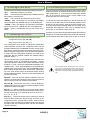
1.6 Rear view
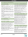
1.3 Front view
Alarms
Option3
Option1
Option2
Units
Logo
123 45
Button ‘LE’
Button ‘UP’
Button ‘SQ’
Front reset for Quick access
counter mode
Signal
Access to
‘Configuration menu’
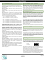
1.4 Power connections
Earth connection - Although a terminal is
offered for earth connection, the connection is optional. The instrument does not
need this connection for correct functioning nor for compliance with the security
regulations.
Power
1.7 Signal connections
8 9 0
1 2 3 4 5
Fuse - To comply with security regulation
61010-1, add to the power line a protection
fuse acting as disconnection element, easily accessible to the operator and identified
as a protection device.
~
+
~
-
Reset
Channel B
Channel A
Power “H” fuse 250mA time-lag
Vexc
Power “L” fuse 400mA time-lag
0V
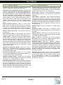
1.5 Sensor configuration and connections
Examples of connections and
configurations for different sensor types.
Connections are indicated for
channel A. For channel B connect the same way, but in channel B.
Note - values indicated on Table1
are usual values. Confirm with
your sensor datasheet the specifications that apply and adapt the
configuration values and connections as needed.
Connections
(for channel A)
Sensor
Mechanical
contact
Namur
0V Channel A
Channel A Vexc
Antirrebound
Trigger
filter
Pulls
Vexc
Pull-up
No
100mSec.
2,5V
Pull-down
9V
No
3,0V
NPN 2 wires
0V Channel A
Pull-up
18V
No
2,5V
NPN 3 wires
0V Channel A Vexc
Pull-up
18V
No
2,5V
PNP 2 wires
0V Channel A
Pull-down
18V
No
2,5V
PNP 3 wires
0V Channel A Vexc
Pull-down
18V
No
2,5V
Push-pull
0V Channel A Vexc
No
18V
No
2,5V
TTL
CMOS
Pick-up
0V Channel A
No
5V
No
2,5V
AC <30V
Inductive
0V Channel A
No
No
No
0V
Table1 - Configuration and connections for different sensor types
Examples for channel A connections
Page 4
Q-DISP-C