1
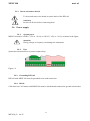
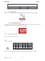
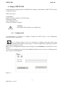
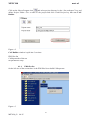
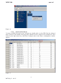
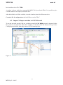
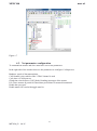
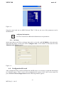
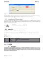
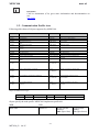
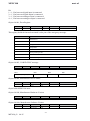
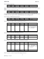
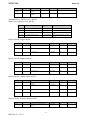
USER’S MANUAL for MPNC100 series ME7020_03 04/15 MPNC100 mect srl 1 ME7020_03 04/15 MPNC100 mect srl INDICE 1 Introduction ..................................................................................................................................................................... 3 1.1 Staff skill ................................................................................................................................................................... 3 1.2 Symbols .................................................................................................................................................................... 3 1.3 Security ..................................................................................................................................................................... 3 2 MPNC100 CANopen ....................................................................................................................................................... 4 2.1 System description .................................................................................................................................................... 4 2.2 Technical data ........................................................................................................................................................... 4 2.3 Installation ................................................................................................................................................................ 7 2.3.1 Distance ............................................................................................................................................................. 7 2.3.2 Wiring description ............................................................................................................................................. 8 2.3.3 Insert and remove board .................................................................................................................................. 12 2.4 Power supply .......................................................................................................................................................... 12 2.4.1 System power ................................................................................................................................................... 12 2.4.2 Fuse .................................................................................................................................................................. 12 2.4.3 Grounding DIN rail .......................................................................................................................................... 12 2.4.4 Shield ............................................................................................................................................................... 12 3.0 MPNC100 operation ................................................................................................................................................... 13 3.1 Description.............................................................................................................................................................. 13 3.1.1 Analogue input and output accuracy ................................................................................................................ 13 3.1.2 Bus Interface .................................................................................................................................................... 14 3.1.3 ID and Baud Rate setup ................................................................................................................................... 14 4 Setup of MPNC100........................................................................................................................................................ 15 4.1 Configuration .......................................................................................................................................................... 15 4.1.1 EDS files list .................................................................................................................................................... 16 4.1.2 Insert node in the net ........................................................................................................................................ 17 4.2 Impor CANopen variables in ATCM Control ........................................................................................................ 18 4.3 Net parameters configuration .................................................................................................................................. 19 4.3.1 ID Setup ........................................................................................................................................................... 20 4.4 Configuration file send ........................................................................................................................................... 20 4.5 Connection to a CANopen master .......................................................................................................................... 21 4.6 Status LED .............................................................................................................................................................. 21 5.0 CANopen .................................................................................................................................................................... 21 5.1 Description.............................................................................................................................................................. 21 5.2 Communication Profile Area .................................................................................................................................. 22 5.3 Error Message (Emergency) ................................................................................................................................... 26 2 ME7020_03 04/15 MPNC100 1. mect srl Introduction To grant a fast setup of the device please follow carefully the information in this manual. 1.1. Staff skill Products described in this manual are devoted to PLC programmers or automation experts only. MECT S.r.l. declines any responsibility about malfunctioning or damage caused by incorrect use of MECT devices, due to noncompliance to this manual information. MECT S.r.l has an help desk. 1.2. Symbols Danger Follow this advice to avoid people injury. Warning Follow this advice to protect the device. Caution Follow this advice to have a more effective performance. ESD ( Electrostatic discharge) Danger: possibly damage due to Electrostatic discharge. Note Step to follow for a correct installation. Additional information 1.3. Security Attention Switch off devices before connecting them. Attention MPNC100 must be mounted inside racks and accessed by qualifyed personnel only. ESD (Electrostatic discharge) Modules have electronic components that can be damaged by. electrostatic discharge. Be sure to be connected to ground when handle the devices. The instrument has no power switch and no internal fuse, but it powers on immediately after connecting a correct power supply input (check the power supply value on the instrument label). Keep the power supply line as short as possible and keep it separate from other power lines. For security reasons it is necessary to have a 2 section power switch with a fuse near the instrument and easily replaceable. Avoid the presence of other power actuators in the same control panel, high humidity, excessive heat and corrosive gas. Instruments must have a power supply from security transformers or SELV transformers. 3 ME7020_03 04/15 MPNC100 mect srl 2. MPNC100 CANopen 2.1. System description MPNC100 is composed by 2 boards, one mounted on a DIN rail (pink in figure) and one expansion board (gray in figure) for analogue and digital Inputs and digital output expansion. MPNC100 communicates with master by a CANopen line. Figure 2-1 Layout MPNC100 2.2. Technical data Power supply 24VAC – 24V VDC Input power MPNC100 3.0 W Analogue Inputs Base board Expansion Board For models MPNC100 01 and MPNC100 02 2 inputs for TA 50Amax (with current transformer SBT002 –itacoil-) 1 input for TV(2.5V=400Vac with voltage transformer SVL101801 –itacoil-) 2 analogue inputs 4÷20mA For models MPNC100 01 and MPNC100 03 8 input for PT100 For models MPNC100 02 and MPNC100 04 4 inputs for PT100 4 inputs 0-10V 2 inputs for PT100 2 analogue inputs 4÷20mA 4 ME7020_03 04/15 MPNC100 mect srl Analogue outputs 1 analogue output 0÷10V 10 bits Base board Expansion board - Digital Inputs Base board 9 NPN / PNP inputs (configurable on request) Expansion board 4 NPN inputs Digital Outputs Base board 12 relay outputs Expansion board 4 relay outputs Bus di campo CANopen Up to 1Mbit/s Mechanic Material Open board Dimensions with expansion board W 110 x 54 x 240 xHxL Mounting DIN 35 Thermal characteristics Working Temperature 0 °C ... 55 °C Storage Temperature -20 °C ... +85 °C Umidity 5 % to 95 % no condensation Isolation Air acc. to IEC 60664-1 Pollution degree acc. to IEC 61131-2 2 IP protection IP protection IP 00 Electromagnetic compatibility Industial Immunity acc. to EN 61000-6-2 (2001) Test specification Values Parameter Class EN 61000-4-2 ESD 4 kV/8 kV (contact/air) 2/3 B EN 61000-4-3 electromagnetic fields 10 V/m 80 MHz ... 1 GHz 3 A EN 61000-4-4 burst 1 kV/2 kV (data/supply) 2/3 B EN 61000-4-5 surge Data: -/- (line/line) 1 kV (line/earth) 5 ME7020_03 04/15 B 2 MPNC100 mect srl EN 61000-4-6 RF disturbances DC sup ply: 0.5 kV (line/line) 1 0.5 kV (line/earth) 1 AC sup ply: 1 kV (line/line) 2 2 kV (line/earth) 3 10 V/m 80 % AM (0.15 ... 80 MHz) 3 B B A Industrial Emission acc. to EN 61000-6-4 (2001) Test specification limit values/IQPI Frequency range Distance EN 55011 (AC supply, conducted) 79 dB (µV) 150 kHz ... 500 kHz 73 dB (µV) 500 kHz ... 30 MHz EN 55011 (radiated) 40 dB (µV/m) 30 MHz ... 230 MHz 10 m 47 dB (µV/m) 230 MHz ... 1 GHz 10 m Distance Industrial Emissionacc. to EN 61000-6-3 (2001) Test specification limit values/IQPI Frequency range EN 55022 (AC supply, conducted) 66 ... 56 dB (µV) 150 kHz ... 500 kHz 56 dB (µV) 500 kHz ... 5 MHz 60 dB (µV) 5 MHz ... 30 MHz EN 55022 (DC supply/data, conducted) 40 ... 30 dB (µA) 150 kHz ... 500 kHz 30 dB (µA) 500 kHz ... 30 MHz EN 55022 (radiated) 30 dB (µV/m) 30 MHz ... 230 MHz 10 m 37 dB (µV/m) 230 MHz ... 1 GHz Attention Mount on rack with no more than 55 °C 6 ME7020_03 04/15 10 m MPNC100 2.3. mect srl Installation 2.3.1. Distance System must be mounted to grant heat exchange and wiring space. Avoid wiring overlap for electromagnetic compatibility. Figure 2-2 7 ME7020_03 04/15 MPNC100 mect srl 2.3.2 Wiring description See figures below for I/Os wiring in various models. MPNC100-01 version Base board(n°8 PT100 + n°2 4÷20mA) Expansion board (n°2 PT100 + n°2 4÷20mA) Figure 2-3 base board wiring Figure 2-4 expansion wiring 8 ME7020_03 04/15 MPNC100 mect srl MPNC100-02 version Base board (n°4 PT100 + n°2 4÷20mA + n°4 0÷10V) Expansion board (n°2 PT100 + n°2 4÷20mA) gnd input2 4-20mA gnd input1 4-20mA gnd TA1 gnd TV1 TA2 13 1312 1211 1110 1009 0908 0807 0706 0605 05 04 03 24Vac input 0-10V gnd input 0-10V gnd input 0-10V gnd input 0-10V pt100_4 pt100_4 pt100_3 pt100_3 pt100_2 pt100_2 pt100_1 pt100_1 28 27 26 25 24 23 22 21 20 19 18 17 16 15 14 power 24Vac gnd 10V 30 29 ingressi PT100 +20Vdc gnd gnd canL canH alimentazione scheda monitor 36 35 35 34 34 33 33 32 32 31 31 36 uscita analogica connettore CanOpen 02 01 + + + + + k k + + 61 62 63 64 65 66 67 68 69 out7 out8 out9 com7-8-9 out10 out11 com10-11 out12 com12 alim Rl3-4 alim Rl1-2 com. alim ingressi NPN out1 out2 com1-2 out3 out4 com3 -4 out5 out6 com5-6 49 4950 5051 5152 5253 5354 5455 5556 5657 5758 5859 5960 60 input 1 input 2 input 3 input 4 gnd input 5 input 6 gnd input 7 input 8 i nput 9 gnd + + 37 38 39 40 41 42 43 44 45 46 47 48 contatti relè abilitazioni relè (Rl1-Rl2-Rl3-Rl4) Figure 2-5 base board wiring Figure 2-6 expansion wiring 9 ME7020_03 04/15 MPNC100 mect srl MPNC100-03 version Base board (n°8 PT100 + n°2 4÷20mA) 04 03 13 12 11 10 09 08 07 06 05 24Vac power 24Vac 28 27 26 25 24 23 22 21 20 19 18 17 16 15 14 +20Vdc gnd 30 29 36 35 34 33 32 31 gnd input2 4-20mA gnd input1 4-20mA gnd TA1 gnd TV1 TA2 pt100_8 com 7-8 pt100_7 pt100_6 pt100_6 pt100_5 pt100_5 pt100_4 pt100_4 pt100_3 pt100_3 pt100_2 pt100_2 pt100_1 pt100_1 connettore per scheda monitor alimentazione scheda monitor ingressi PT100 gnd 10V uscita analogica 02 01 + + + + + k k + + 61 62 63 64 65 66 67 68 69 out7 out8 out9 com7-8-9 out10 out11 com10-11 out12 com12 alim Rl3-4 alim Rl1-2 com. alim ingressi NPN out1 out2 com1-2 out3 out4 com3 -4 out5 out6 com5-6 49 50 51 52 53 54 55 56 57 58 59 60 input 1 input 2 input 3 input 4 gnd input 5 input 6 gnd input 7 input 8 i nput 9 gnd + + 37 38 39 40 41 42 43 44 45 46 47 48 contatti relè abilitazioni relè (Rl1-Rl2-Rl3-Rl4) Figure 2-7 base board wiring 10 ME7020_03 04/15 MPNC100 mect srl MPNC100-04 version Base board (n°4 PT100 + n°2 4÷20mA + n°4 0÷10V) gnd input2 4-20mA gnd input1 4-20mA gnd TA1 gnd TV1 TA2 13 1312 1211 1110 1009 0908 0807 0706 0605 05 04 03 24Vac input 0-10V gnd input 0-10V gnd input 0-10V gnd input 0-10V pt100_4 pt100_4 pt100_3 pt100_3 pt100_2 pt100_2 pt100_1 pt100_1 28 27 26 25 24 23 22 21 20 19 18 17 16 15 14 power 24Vac gnd 10V 30 29 ingressi PT100 +20Vdc gnd gnd canL canH alimentazione scheda monitor 36 35 35 34 34 33 33 32 32 31 31 36 uscita analogica connettore CanOpen 02 01 + + + + + k k + + 61 62 63 64 65 66 67 68 69 out7 out8 out9 com7-8-9 out10 out11 com10-11 out12 com12 alim Rl3-4 alim Rl1-2 com. alim ingressi NPN out1 out2 com1-2 out3 out4 com3 -4 out5 out6 com5-6 49 4950 5051 5152 5253 5354 5455 5556 5657 5758 5859 5960 60 input 1 input 2 input 3 input 4 gnd input 5 input 6 gnd input 7 input 8 i nput 9 gnd + + 37 38 39 40 41 42 43 44 45 46 47 48 contatti relè abilitazioni relè (Rl1-Rl2-Rl3-Rl4) Figure 2-8 base board wiring 11 ME7020_03 04/15 MPNC100 mect srl 2.3.3. Insert and remove board To insert and remove the board act on the hook of the DIN rail. Attention Switch off devices before connecting them. 2.4. Power supply 2.4.1. System power MPNC100 needs a 24VDC (-15% or +20 %) or 24VAC (-15% or +20 %) as shown in the figure. Attention Wrong voltage or frequency can damage the instrument. 2.4.2. Fuse System has an internal fuse to protect output relays. Figure 2-9 2.4.3. Grounding DIN rail DIN rail with MPNC100 must be grounded to an earth connection. 2.4.4. Shield Cable between CAN master and MPNC100 must be shielded and connected to ground at both sides. 12 ME7020_03 04/15 MPNC100 3.0 mect srl MPNC100 operation 3.1 Description MPNC100 is a CANopen DS401 node with 7 PDO in transmission and 4 in receiver. Node variables are in the following table: Variable Type PDO Direction PDO Digital inputs 1 – 8 Digital inputs 9 – 14 Digital oututs 1 – 8 Digital oututs 9 – 16 PT100 – 1 PT100 – 2 PT100 – 3 PT100 – 4 Voltage input 0 – 10V - 1 / PT100 – 5 Voltage input 0 – 10V - 2 / PT100 – 6 Voltage input 0 – 10V - 3 / PT100 – 7 Voltage input 0 – 10V - 4 / PT100 – 8 TV 0 – 100Vac TA1 0 – 100mA TA2 0 – 100mA Current input 4 – 20mA – 1 Current input 4 – 20mA – 2 Expansion Current input PT100 – 1 Expansion input PT100 – 2 Expansion Current input 4 – 20mA – 1 Expansion Current input 4 – 20mA – 2 Phase between TV and TA1 Phase between TV and TA2 Frequency TV Frequency TA1 Frequency TA2 Voltage output 0 – 10V BYTE BYTE BYTE BYTE INT INT INT INT INT INT INT INT INT INT INT INT INT INT INT INT INT INT INT INT INT INT INT 1 1 1 1 2 2 2 2 3 3 3 3 4 4 4 4 5 5 5 5 6 6 6 6 7 7 2 TX TX RX RX TX TX TX TX TX TX TX TX TX TX TX TX TX TX TX TX TX TX TX TX TX TX RX 3.1.1. Analogue input and output accuracy Base board 2 TA inputs 4 PT100 inputs 4 0-10V inputs 2 4÷20mA inputs 1 TV 100Vac input 1 0÷10V analogue output Range 0-100mAac -40.0°C - 200.0°C 0 - 10.00V 0 - 20.00mA 0 - 100.0Vac 0 - 10.00V 13 ME7020_03 04/15 Accuracy 1% vfs 0.5% vfs 0.5% vfs 0.5% vfs 1% vfs 1% vfs MPNC100 mect srl Expansion board -40.0°C - 200.0°C 0.5% vfs 0 - 20.00mA 0.5% vfs 4 PT100 input 2 4÷20mA inputs 3.1.2. Bus Interface MPNC100 is a CANopen DS401 node, connected to field by a 6 terminal board as in figure. Figure 3-1 3.1.3. ID and Baud Rate setup User can set with a DIP switch, the ID and Baud Rate. Address is set by dip 1 and 2 (address 1 to 4), Baud Rate set by dip 3 and 4. See table below for settings. Figure 3-2: Node address setup(ID) To set 1 on DIP switch switch to ON. Address is as in table S-1 S-2 ID nodo S-4 S-3 Baudrate 0 1 0 1 0 0 1 1 1 2 3 4 0 1 0 1 0 0 1 1 125/kb/s 250/kb/s 500kb/s 1Mbit/s Dip are read at power on of the instrument, so after set up power off and on the instrument. 14 ME7020_03 04/15 MPNC100 mect srl 4. Setup of MPNC100 In this chapter the setup procedure of a MPCN100 CANopen node linked to a MECT TPAC master CANopen is shown. Follow these steps: Configuration Import CANopen variables in ATCM Control Set baudrate and ID send configuration file Connect to a Master CANopen Attention Description in this chapter is an example only. 4.1. Configuration To communicate it is necessary to configure CANopen net. MECT gives a free configuration software to easily setup the net. To use CANopen nodes in a net, it is necessary to configure each node and to setup communication parameters to the master. To do the configuration an application software of the master constructor is used. MECT gives a configuration software for the CANopen net (CAN Builder) on which TPAC are the masters. To access the configurator by means of the dashboard interface open or create a CANopen project in the section of the Dashboard. Figure 4-1 15 ME7020_03 04/15 MPNC100 mect srl Click on the Nuovo Progetto icon and select project directory by the “Set workspace” key and define Project Folder. Give a name to the project and click Create Project key that runs CAN Builder. Figure 4-2 CAN Builder window is split into 3 sections: EDS files list CANopen node of the net net parameters setup 4.1.1. EDS files list On the left size of the screen there is the EDS files list to build CANopen net. Figure 4-3 16 ME7020_03 04/15 MPNC100 mect srl Figure 4-4 4.1.2. Insert node in the net To insert an MPNC100 node in the CANopen net, double click it on the EDS files list. Selected node is placed on the middle of the page and a default net ID is assigned: first available ID. Then select it, press right mouse key, and select Configure node in the menu a configuration window appears. Figure 4-5 17 ME7020_03 04/15 MPNC100 mect srl In the window select TAG: PDO A window is shown with objects managed by MPNC100 by read/write PDOs. It is possible to give a variable name to each object, used inside PLC. After the definition of all the variables, close the window, then in the file menu select: Costruisci file di configurazione thet build files to send to TPAC 4.2. Impor CANopen variables in ATCM Control To use the net node on the CAN net, variables created in CAN Builder must be imported in the PLC project to use them like others PLC variables. To do this, select file ResourceCan.gvl in the CANopen project folder, then drag it in the ATCM Control project. Figure 4-6 18 ME7020_03 04/15 MPNC100 mect srl Figure 4-7 4.3. Net parameters configuration To communicate master and slave must have correct net parameters. In the right side of the window there are the parameters to configure CANopen net: Baudrate: speed of data transmission CAN channel: select which of the 2 TPAC channel is used Cycle time of CANopen net Guard time: time between 2 NG (Node Guarding) messages of the master Life Time: numero di periodi di Guard time period time for master disconnected Enable the sync send Enable master NG send with toggle state bit 19 ME7020_03 04/15 MPNC100 mect srl Figure 4-8 Setup the same baud rate on MPNC100 and TPAC CAN net, the rest of the parameters can be modified later. Additional information See TPAC tutorial for additional information on net parameters 4.3.1. ID Setup master must know node ID to exchange data with it, to do this runCAN Builder, select the node, right click the mouse, in the menu select Configura nodo, in the window set the node ID in the Administration Objects section. Figure 4-9 4.4. Configuration file send After configuration files creation and baud rate and ID setup, it is necessary to send this information to CANopen master. TPAC receives this configuration by means of the LAN. In the menu File press: Scarica i file di configurazione and the following window appears: 20 ME7020_03 04/15 MPNC100 mect srl Figure 4-10 In the IP address section it is possible to setup the master address in the LAN network, the n press Connessione al Pannello Operatore, and the configuration files are transferred. 4.5. Connection to a CANopen master To use data collected by MPNC100 it is necessary to connect it to a CANopen master. Connect MPCN100 to TPAC, power both instruments, a configuration session starts, at the end MPNC100 begins to exchange data with TPAC. Attention Setup baudrate and ID also on MPNC100. 4.6. Status LED On MPNC100 there is a status LED showing the node status. See table below for the message coding of the LED. In the table the LED status is shown as below: ON on OFF off Bc: blinking LED ON OFF Bc 5.0 STATUS Run startup Preoperational Description MPNC100 is configured and running Off MPNC100 is being configuring CANopen 5.1 Description CANopen is a serial net based un CAN bus. CANopen specification are defined by CIA (CAN in automation) and described by document DS301. Unlike other protocols, modules on bus have no address, but they are identified by messages. Conflicts on bus are solved at message level and only highest priority message are passed. 21 ME7020_03 04/15 MPNC100 mect srl Information CAN in Automation (CiA) gives more information and documentation on site: can-cia.de 5.2. Communication Profile Area Following table shows all objects supported by MPNC100. Idx Nome Tipo Significato 0x1000 0x1001 0x1005 0x1008 Device Type Error Register COB-ID SYNC message Manufacturer Device Name Manufacturer Hardware Version Manufacturer Software Version Guard Time Life Time Factor Store Parameters Restore default Parameter Unsigned32 Unsigned8 Unsigned32 Visible String Device Profile Errors are bit coded (DS401) COB-ID of the SYNC object Device name Visible String Hardware version Visible String Software version Unsigned16 Unsigned8 Array Unsigned32 Array Unsigned32 COB-ID Emergency Object Receive PDO Communication Parameter Unsigned32 Time for “Life Guarding Protocol“ Life Time Factor Parameter to store the configuration Parameter to restore the default configuration COB-ID for the emergency Object Record PDO Paramter Communication parameter for the Rx PDO 0x1600 0x160F Receive PDO Mapping Parameter Record PDO Mapping Mapping parameter for the Rx PDO 0x1800 0x180F Transmit PDO Communication Parameter Record PDO Paramter Communication parameter for the Transmit PDO 0x1A00 0x1A0F Transmit PDO Mapping Parameter Record PDO Mapping Mapping parameter for the Transmit PDO 0x1009 0x100A 0x100C 0x100D 0x1010 0x1011 0x1014 0x1400 0x140F Object 0x1000, Device Type Indice Sub indice Nome Tipo Attributi Default 0x1000 0 Device Type Unsigned32 RO - Object specify the node profile. MPNC010 implements profile 401. MSB 0000.0000 LSB 0000.4321 Device Profile Device Profile Number: Number: 0x01 (Byte Alto) 0x91 (Byte basso) 22 ME7020_03 04/15 MPNC100 mect srl Bit 1 = 1, If at least one digital input is connected 2 = 1, If at least one digital output is connected 3 = 1, If at least one analogue input is connected 4 = 1, If at least one analogue output is connected Object 0x1001, Error Register Indice Sub indice Nome Tipo Attributi Default 0x1001 0 Error Register Unsigned 8 RO - This registry holds the internal errorsand is also part of the emergency message. Bit Significato 0 General Error 1 Current 2 Voltage 3 Temperature 4 Communication 5 Device profile specific 6 Reserved 7 Manufacturer specific Object 0x1005, COB-ID SYNC message Indice Sub indice Nome 0x1005 0 COB-ID SYNC Unsigned 32 Bit31 Tipo Bit11 Attributi Default RW 0x00000080 Bit10 Riservato (sempre 0) Bit0 COB-ID Object 0x1008, Manufacturer Device Name Indice Sub indice Nome Tipo Attributi Default 0x1008 0 Manufacturer Device Name Visible String RO 0 Object holds MPNC100 name Object 0x1009, Manufacturer Hardware Version Indice Sub indice Nome Tipo Attributi Default 0x1009 0 Manufacturer Hardware Version Visible String RO Current HW-Version Attributi Default RO Current SW-Version Object 0x100A, Manufacturer Software Version Indice Sub indice Nome Tipo 0x100A 0 Manufacturer Soft- Visible ware Version String 23 ME7020_03 04/15 MPNC100 mect srl Object 0x100C, Guard Time Indice Sub indice Nome Tipo Attributi Default 0x100C 0 Guard Time Unsigned16 RW 0 Object holds time in millisecond, the master frequency request to the slave for the status (Guard Time) Object 0x100D, Life Time Factor (LFT) Indice Sub indice Nome Tipo Attributi Default 0x100D 0 Lifetime Factor Unsigned8 RW 0 LifeTime Factor is part of the Node Guarding protocol. If slave verifies an elapsed time more than LTF*NG since last reception of NG, assumes that master is not working properly. Object 0x1014, COB-ID Emergency Object Indice Sub indice Nome Tipo Attributi Default 0x1014 0 COB ID EMCY Unsigned32 RW 0x80+Module-ID Object 0x1400– 0x140F, Rx PDO Communication Parameter Indice Sub indice Nome Tipo Attributi Default 0x1400 0x140F 0 Unsigned 8 RO 2 1 Max. supported Entries COB-ID Unsigned 32 RW Idx 0x1400 0x200 + Module ID Idx 0x1401 0x300+Module-ID Idx 0x1402 0x400+Module-ID Idx 0x1403 0x500+Module-ID Idx 0x1404-141F 0x80000000 2 Transmission type Unsigned 8 RW 255 Object 0x1600– 0x160F, Rx PDO Mapping Parameter Indice Sub indice Nome 0x1600 0x160F 0 Number of mapped Unsigned 8 Objects 1.Object to Unsigned32 8.Object 1 to 8 Tipo Attributi Default RW - RW - Object 0x1800– 0x180F, Transmit PDO Communication Parameter Indice Sub indice Nome Tipo Attributi Default 0x1800 0x180F 0 Unsigned8 RO 5 1 Max. supported Entries COB-ID Unsigned 32 RW Idx 0x1800 0x180+Module-ID 0x1801 0x280+Module-ID 0x1802 0x380+Module-ID 0x1803 0x480h+Module ID 0x1804 0x80000000 2 3 Transmission type Unsigned 8 Inhibit Time Unsigned 16 RW RW 255 - Object 0x1A00 – 0x1A04, Transmit PDO Mapping Parameter 24 ME7020_03 04/15 Idx Idx Idx Idx MPNC100 mect srl Indice Sub indice Nome 0x1AA00 0x1A0F 0 Number of mapped Unsigned 8 Objects 1.Object to Unsigned 32 8.Object 1 to 8 Tipo Attributi Default RW - RW - Standard Device Profile Area – DS 401 MPNC100 supports profile DS 401, Idx Nome Tipo Significato 0x6000 Read Input 8 Bit Array Unsigned8 Data of digital input I/O modules 0x6200 Write Output 8-Bit Array Unsigned8 Data of digital output I/O modules 0x6401 Read Analog Input 16-Bit Array Unsigned16 0x6411 Write Analog Output 16-Bit Array Unsigned16 Data of analog input I/O modules (16 bit) Data of analog output I/O modules (16 bit) Object 0x6000, Digital Inputs Indice Sub indice Nome Tipo Attributi Default 0x6000 0 Number of digital input blocks Unsigned 8 RO - 1 1. input block Unsigned 8 RO - 2 2. input block Unsigned 8 RO - Object 0x6200, Digital Outputs Indice Sub indice Nome Tipo Attributi Default 0x6200 0 Number of digital output blocks Unsigned8 RO - 1 1. output block Unsigned8 RW 0 2 2. output block Unsigned8 RW 0 Object 0x6401, Analog Inputs 16 Bit Indice Sub indice Nome Tipo Attributi Default 0x6401 0 Unsigned8 RO - 1 Number analog input channels (16Bit) 1. channel Unsigned16 RO - .... .... .... .... .... 4 4. channel Unsigned16 RO - Object 0x6411, Analog Outputs 16 Bit Indice Sub indice Nome Tipo Attributi Default 0x6411 0 Number analog output channels (16Bit) Unsigned8 RO - 25 ME7020_03 04/15 MPNC100 mect srl 1 1. channel Unsigned16 RW 0 .... .... .... .... .... 4 4. channel Unsigned16 RW 0 5.3. Error Message (Emergency) Emergency message is sent in the event of a critical event that must be known by net components. Structure and coding of emergency messages are in the table below: Byte: 0 1 2 3 7 Nome Codice di Registro di errore errore Note 0x0000* 0x00 00 00 00 00 00 Power ON message 0x8100* 0x80 00 01 00 00 00 0x8100* 0x80 00 02 00 00 00 The time between two node guarding telegrams is greater than Guard_Time * Life_Time_Faktor. The time span between two SyncObjects is longer than the communication_Cycle_Period 0xFF00* 0x80 00 02 EE EE NN Error on terminal - EE: code - NN :terminal in error number 26 ME7020_03 04/15