1
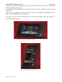
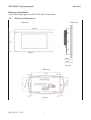
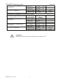
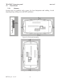
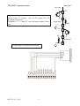
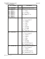
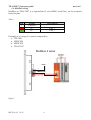
USER’S MANUAL for
TPAC1007 03 series
Operator panel
ME7036_04
10/15
TPAC1007 Operator panel
mect srl
INDEX
1. Introduction.............................................................................................................. 2
1.1. Staff skill ........................................................................................................... 2
1.2. Symbols............................................................................................................. 2
1.3. Terms ................................................................................................................ 3
1.4. Security ............................................................................................................. 3
1.5. REFERENCE MANUAL ................................................................................. 3
2. System description ................................................................................................... 3
2.1. Specification ..................................................................................................... 5
2.2. Mechanical dimensions .................................................................................... 7
2.3. Panel mount .................................................................................................... 10
2.3.1. Distance ....................................................................................................... 10
3. Connections TPAC1007 03 ................................................................................... 11
3.1 Isolation........................................................................................................... 11
3.2 System power supply ...................................................................................... 11
3.2.1 Fuse .............................................................................................................. 12
3.3
3.4
IO wiring ......................................................................................................... 13
System variables ............................................................................................. 15
3.5
Variables use in a program ............................................................................. 16
3.6
ModBus wiring ............................................................................................... 17
4 Peripherals ............................................................................................................. 18
4.1
USB ................................................................................................................. 18
4.2 Ethernet ........................................................................................................... 18
5 HMI ........................................................................................................................ 18
6 How to order .......................................................................................................... 18
ME7036_04
10/15
1
TPAC1007 Operator panel
mect srl
1. Introduction
To grant a fast setup of the device please follow carefully the information in this
manual.
1.1. Staff skill
Products described in this manual are devoted to PLC programmers or automation
experts only. MECT S.r.l. declines any responsibility about malfunctioning or
damage caused by incorrect use of MECT devices, due to noncompliance to this
manual information. MECT S.r.l has an help desk.
1.2.
Symbols
Danger
Follow this advice to avoid people injury.
Warning
Follow this advice to protect the device.
Caution
Follow this advice to have a more effective performance.
ESD ( Electrostatic discharge)
Danger: possibly damage due to Electrostatic discharge.
Note
Step to follow for a correct installation.
Additional information
ME7036_04
10/15
2
TPAC1007 Operator panel
1.3. Terms
PLC:
Terminals:
System:
1.4.
mect srl
TPAC1007
TPLC005, MPNC010, MPNC020, MPNC030
PLC (TPAC1007) with terminals
Security
Attention
Switch off devices before connecting them.
ESD (Electrostatic discharge)
Modules have electronic components that can be damaged by.
electrostatic discharge. Be sure to be connected to ground when
handle the devices.
The instrument has no power switch and no internal fuse, but it powers on
immediately after connecting a correct power supply input (check the power supply
value on the instrument label). Keep the power supply line as short as possible and
keep it separate from other power lines.
For security reasons it is necessary to have a 2 section power switch with a fuse near
the instrument and easily replaceable.
Avoid the presence of other power actuators in the same control panel, high humidity,
excessive heat and corrosive gas.
Instruments must have a power supply from security transformers or SELV
transformers.
1.5. REFERENCE MANUAL
ME7028
Mect configurator
ME7041
Quick Start
2. System description
TPAC1007 is a device composed by a PLC and a HMI with touch-screen monitor
4.3” width and 480 x 272 pixel resolution with 262.000 colors.
TPAC1007 allows the supervision of networked Modbus RTU and Modbus TCP
devices. The networks are managed simultaneously by TPAC1007 and data from a
network can be sent to another thus creating a bridge between the two networks.
On TPAC1007 a Micro-USB host port is present, that allows, with an adapter, the use
of an USB-pen drive for software updates and data log.
On TPAC1007 are up to 1 Kbyte of retentive variables stored on flash.
ME7036_04
10/15
3
TPAC1007 Operator panel
mect srl
The device is also able to manage an up to 8GB wide, micro SD card. The SD card is
factory mounted on request.
A real-time clock maintains the date and time up to four months with the device
turned off.
TPAC1007 is equipped with a micro PLC with several digital and analogue I/O to
make a small automation of the process.
The device can be used in horizontal or in vertical orientation with the option "V"
(see following pictures).
Figure 1: Front view TP1007 (horizontal version)
Figure 2: Front view TP1007 (vertical version)
ME7036_04
10/15
4
TPAC1007 Operator panel
mect srl
2.1. Specification
TPAC1007 is based on a multiprocessor system. PLC and HMI are based on a
454MHz ARM9.
Table 1
PLC Hardware characteristics
PLC Processor
RAM
FLASH
Non volatile variables
Real Time Clock
Screen
Touch screen
Ethernet
Micro-USB
Micro SD
PLC software characteristics
OS
PLC
Graphics
ModBus
Storage memory
Field bus main features
RTU Modbus
TCP Modbus
Tensione di alimentazione
24VDC
Power
ME7036_04
10/15
ARM926JE 454MHz
128MB
128MB
On FLASH memory
Yes with rechargeable battery
TFT 480 x 272 pixel 262k colors
Resistive 4 wires
10Mbit/s - 100Mbit/s self recognition
Host 2.0
Max 8GB
LINUX 2.35
IEC61131-3
Based on QT library
Modbus RTU master
Possibility of history storage
Master 2 wires
Client
+20% - 10%
3.5W digital output off
5
TPAC1007 Operator panel
Analogue inputs
Analogue output
Digital inputs or
encoder inputs
Digital I/O
Power supply
Serial output
ME7036_04
10/15
mect srl
TPAC1007 03 Expansion features
Input type
Resolution Bit
0.01mA
0¸20 mA
12
0.005V
12
0¸10V
thermocouples
12
J(0°C – 600°C),
N° 2 T(0°C – 400°C),
1°C
K(0°C – 1200°C)
PT100 r -40.0°C
0.1°C
12
– 200.0°C
PT100 E
1°C
12
-40°C-800°C
Output type
Resolution Bit
0.005mA
10
N° 1 4¸20 mA
0-10V
0.003V
10
Input type
Resolution Bit
N°4
o
1
N°8
Note
Input impedance 9W
Input impedance 1MW
Cold junction
compensation
Note
Max impedance: 400W
Min impedance: 1KW
Note
Inputs 2 e 3 can be
PNP
max
used as incremental
or
frequency
encoder
Bidirectional 500Hz
max input frequency:
32 40kHz
Encoder
D2: input A
D3: input B
I/O Type
Resolution Bit
Note
Max
200mA max for each
PNP software
Frequency
output. 2 A max all
configurable
500Hz
outputs.
24Vdc ±15% 400mA
Isolated half duplex RS485 Modbus
6
TPAC1007 Operator panel
mect srl
Hardware installation
In the following figures see the TPAC1007 dimensions.
2.2.
Mechanical dimensions
Side view
Rear view
Figure 3
Figure 4
Side view
Figure 5
ME7036_04
10/15
7
TPAC1007 Operator panel
Technical specification
mect srl
Table 2
Mechanical
Material
ABS, Polycarbonate
41 mm x 159 mm x 83 mm
Dimensions W x L x H
Mounting plate
127mm x 68mm
Installation
Panel installation
Environmental conditions
Operative temperature
0 °C ... 55 °C
Storage Temperature
-20 °C ... +85 °C
Relative Humidity
5 % a 95 % no condensation
Electric isolation
Air clearance
According to IEC 60664-1
Pollution
2
According to IEC 61131-2
Protection
Rear protection
IP 20
Front protection
IP 65
EMC
EMC according to EN 61000-6-2 (2001)
Test specification
EN 61000-4-2 ESD
EN 61000-4-3
electromagnetic fields
EN 61000-4-4 burst
EN 61000-4-5 surge
Values
4 kV/8 kV (contact/air)
10 V/m 80 MHz ... 1 GHz
1 kV/2 kV (data/supply)
Data:
-/- (line/line)
1 kV (line/earth)
DC
0.5 kV (line/line)
supply:
0.5 kV (line/earth)
AC
1 kV (line/line)
supply:
2 kV (line/earth)
EN 61000-4-6
10 V/m 80 % AM (0.15 ... 80
RF disturbances
MHz)
Emissions according to EN 61000-6-4 (2001)
Test specification
ME7036_04
10/15
Limit
values/IQPI
8
Class
Criterion
2/3
3
B
A
2/3
B
B
2
1
1
2
3
3
Frequency
Range
B
B
A
Distance
TPAC1007 Operator panel
EN 55011 (AC supply,
conducted)
mect srl
79 dB (µV)
73 dB (µV)
EN 55011 (radiated)
40 dB (µV/m)
47 dB (µV/m)
Emissions according to EN 61000-6-3 (2001)
Test specification
Limit
values/IQPI
EN 55022 (AC supply,
66 ... 56 dB
conducted)
(µV)
56 dB (µV)
60 dB (µV)
EN 55022 (DC supply/data,
40 ... 30 dB
conducted)
(µA)
30
dB (µA)
EN 55022 (radiated)
30 dB (µV/m)
37 dB (µV/m)
150 kHz ... 500
500 kHz ... 30
MHz
30 MHz ... 230
MHzMHz ... 1
230
GHz
Frequency
Range
150 kHz ... 500
kHz
500 kHz ... 5
MHz
5
MHz ... 30
MHzkHz ... 500
150
kHz
500 kHz ... 30
MHz
30 MHz ... 230
MHzMHz ... 1
230
GHz
Attention
Install the device in a panel with no more than 55 °C.
ME7036_04
10/15
9
10 m
10 m
Distance
10 m
10 m
TPAC1007 Operator panel
2.3. Panel mount
mect srl
2.3.1.
Distance
System must be installed with a space for heat dissipation and cabling. Avoid
superimposing cabling to avoid EMC problems.
Figure 6A: Horizontal mounting
Figure 6B: Vertical mounting
ME7036_04
10/15
10
TPAC1007 Operator panel
3. Connections TPAC1007 03
mect srl
Wiring description
pt100_1
in_1/pt100_1
gnd1
pt100_2
in_2/pt100_2
gnd
out_V
gnd1
out_mA
-
In the following figure see the wiring diagram.
4 5
6
7
8
9 10 11
24Vpot
3
in12
in11/EncZ
gnd1
in10/EncB
in9/Enc A
out1/in1
out2/in2
out3/in3
out4/in4
out5/in5
out6/in6
out7/in7
out8/in8
gnd1
1 2
16 17 18 19 20 21 22 23 24 25 26 27 28 29 30
LAN
Micro
USB
DD+
gn diso
gn d2
24 V dc
1 2 3 4 5
Figure 7
Legend :
· GND: ground reference for analog and digital I/O
· GND2: ground power separated by a diode respect to the GND ground
· GNDISO: Modbus optoisolated ground
Power supply
3.1 Isolation
Device has no galvanic isolation between input, output and power supply.
3.2 System power supply
TPAC1007 has a 24Vdc (-10 /+20%) , the main board and the expansion board as
well, according to the scheme in the below figure. Both supply can be connected to
the same power supply.
The circuit of the digital outputs is powered by the 29 (-) and the 30 (+) terminals.
This circuit can be externally separated by a switch of power.
System is protected against reverse power supply.
ME7036_04
10/15
11
TPAC1007 Operator panel
mect srl
LAN
Micro
USB
12 345
gnd
500mA
+24Vdc
+24Vpot
emergency
Figure 8
Attention
A wrong value for the power supply can cause a damage to the
device
3.2.1 Fuse
System has no internal fuse , so it is suggested the use of an external 500mA fuse for
the panel power supply.
ME7036_04
10/15
12
mect srl
3 wire PT100 input. Wiring with too high
resistance can cause measure errors. To use 2 wire
PT100 short terminals 2 and 3.
blue
red
red
TPAC1007 Operator panel
3.3 IO wiring
Analogue and digital wiring
pt100_1
in_1/ pt100_1
gnd
1 2 3 4 5 6 7 8 9 10 11
+
-
T/C input. Thermocouples must be isolated type.
Use only proper thermocouples wire.
pt100_1
in_1/ pt100_1
gnd
1 2 3 4 5 6 7 8 9 10 11
power source
-
+
+
mA/V Input. Analogue inputs 4÷20mA and 0÷10V
are connected to input and GND terminals. See
figure to connect a 2 wire transducer with external
power supply.
-
p t100_1
in _1/p t100_1
gn d
1 2 3 4 5 6 7 8 9 10 11
ME7036_04
10/15
13
TPAC1007 Operator panel
mect srl
TPAC1007
30 +24V
Digital I/O. Terminals 21 ÷ 28 can be configured as
digital input or output . See in the figure the 28
terminal connection.
Terminals “17, 19 and 20” are high speed inputs (freq,
ect)
28
digital output
29
Rload
+24V 30
Rin
28
digital input
29
Connecting to bidirectional encoder.
ME7036_04
10/15
14
TPAC1007 Operator panel
mect srl
3.4 System variables
PLC variable
PLC_StatusReg
PLC_DigDir_1
PLC_DigDir_2
PLC_DigDir_3
PLC_DigDir_4
PLC_DigDir_5
PLC_DigDir_6
PLC_DigDir_7
PLC_DigDir_8
PLC_AnInConf_1
Description
Type
UINT Expansion firmware revision
INT 8 Digital I/O configuration:
· 0 input
· 1 output
Ex°: ch3 = output
PLC_DigDir_3 := 1;
UINT Analogue input configuration:
· 0 not configured
· 1 current
· 2 voltage
· 3 TCJ
· 4 TCK
· 5 TCT
· 6 PT100E
· 7 PT100R
Ex°: ch1 = TCT
PLC_AnInConf_2
PLC_AnInConf_1 := 5;
UINT Analogue input configuration:
· 0 not configured
· 1 current
· 2 voltage
· 3 TCJ
· 4 TCK
· 5 TCT
· 6 PT100E
· 7 PT100R
Ex°: ch1= not configured
PLC_AnOutConf_1
PLC_AnOutConf_1 := 0;
UINT Analogue output configuration:
· 0 not configured
· 1 current
· 2 voltage
Ex°: ch1= not configured
PLC_AnOutConf_1 := 0;
ME7036_04
10/15
15
TPAC1007 Operator panel
PLC_DigIn_1
PLC_DigIn_2
PLC_DigIn_3
PLC_DigIn_4
PLC_AnIn_1
PLC_AnIn_2
PLC_Tamb
PLC_EncoderLo
PLC_EncoderHi
PLC_DigOut_1
PLC_DigOut_2
PLC_DigOut_3
PLC_DigOut_4
PLC_DigOut_5
PLC_DigOut_6
PLC_DigOut_7
PLC_DigOut_8
PLC_AnOut_1
PLC_EncEnable
PLC_EncoderReset
mect srl
INT
Digital inputs value
(Up to 12 digital inputs
depending of the number of
digital outputs that need à 8 are
configurable)
INT Analogue input value
INT Analogue input value
INT Temperature of cold junction
UINT Reading encoder (lower part)
UINT Reading encoder (upper part)
INT Digital output value
INT Analogue output value
UINT Enable encoder:
· 0: disable encoder
· 1: enable bidirectional
encoder
Ex°: Encoder = disable
PLC_EncEnable := 0;
UINT Encoder reset
3.5 Variables use in a program
To use expansion board IO in a PLC insert statement #import
“LIO_TPAC1007.gvl” in the program or function block where you need expansion
variables.
After that the variables are available in read / write mode as described in the program
tutorial.
The system can use 5472 interchange variables between HMI and automation (at
maximum) which include:
internal variables, interchange variables on Modbus network, retentive variables.
The variables are defined by a software “Mect Suite” .
ME7036_04
10/15
16
TPAC1007 Operator panel
mect srl
3.6 ModBus wiring
ModBus on TPAC1007 is a optoisolated 2 wire RS485 serial line, on the terminal
board on pins:
Table 3
Pin
3
2
1
Signal
GNDiso
D+
D-
Description
Line +
Line -
Example of a wiring of a system composed by:
· TPLC005
· MPNC020
· MPNC030
· TPAC1007
ModBus 2 wires
24Vdc
5
4
3
2
1
+
GND iso
+
-
Figure 9
ME7036_04
10/15
17
TPAC1007 Operator panel
4 Peripherals
mect srl
4.1USB
TPAC1007 has a Micro-USB 2.0 host for:
· software update
· data storage: datalogger
· connect USB peripherals as printers, mouse, etc.
Specific connection of external peripherals are implemented on request.
4.2 Ethernet
TPAC1007 has a 10/100Mbit/s ethernet port with auto-configuration, the connection
cable between TPAC1007 and a personal computer can be either straight or cross.
5 HMI
To set the TPAC1007 is necessary to develop a software in QT Creator based on QT
libraries, custom-tailored on MECT operator panel.
A specific tutorial is furnished with the device.
The QT Creator software suite is available in Windows environment.
6 How to order
ME7036_04
10/15
18