1
ASSEMBLAD S.r.l.
Costruzioni Elettroniche
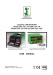
Sampling SMOKE METER
Model OPA – 198
USER MANUAL
Oct. 2006, Rev. V 2.2’0
ASSEMBLAD – Engineering Departement – Automotive division
GB
Assemblad s.r.l
OPA-198 - User Manua
ASSEMBLAD S.r.l. - Costruzioni Elettroniche - Servizio Assistenza Tecnica Clienti
Via Marzabotto, 4 - 50013 Campi Bisenzio - Firenze - Italia
Tel. 055-890485 r.a. - Fax. 055-890496 - E-mail: [email protected] –Web: www.assemblad.it
2
Assemblad s.r.l
OPA-198 - User Manua
Note:
ASSEMBLAD S.r.l. - Costruzioni Elettroniche - Servizio Assistenza Tecnica Clienti
Via Marzabotto, 4 - 50013 Campi Bisenzio - Firenze - Italia
Tel. 055-890485 r.a. - Fax. 055-890496 - E-mail: [email protected] –Web: www.assemblad.it
3
Assemblad s.r.l
OPA-198 - User Manua
TABLE OF CONTENTS
1 INTRODUCTION ...........................................................................................................5
2 TECHNICAL FEATURES ..............................................................................................6
2.1 PHOTODETECTOR TECHNICAL FEATURES..........................................................6
2.2 MEASURING CHAMBER TECHNICAL FEATURES..................................................6
2.3 ELECTRONIC STRUCTURAL FEATURES ...............................................................6
2.4 POWER SUPPLY .......................................................................................................7
2.5 OTHER FEATURES ...................................................................................................7
2.6 FITTINGS SUPPLIED.................................................................................................7
3 STARTING THE SMOKE METER.................................................................................8
3.1 POWER SUPPLY CONNECTIONS ...........................................................................8
3.2 PREPARATION FOR MEASUREMENTS ..................................................................8
4 INFPLUSWIN SOFTWARE ...........................................................................................9
4.1 Features of the program ................................................................................................9
4.2 Installation .....................................................................................................................9
1.3 Running InfplusWin .....................................................................................................10
4.4 Set-Up section .............................................................................................................12
4.5 Smoke Meter section ...................................................................................................15
4.6a. Type of device ......................................................................................................16
4.6b. Smoke Meter 's status ...........................................................................................16
4.6c. Type of “Block of the Smoke” (only for OPA-105)..................................................16
4.6d. Setting the type of measurement ..........................................................................16
4.6e. Measurements .......................................................................................................17
4.6f. Sub form of test limits and manufacturer's data.....................................................18
4.6g. Message window ...................................................................................................18
4.6h. Test result window .................................................................................................19
4.6i. Intermediate test result window ..............................................................................19
4.6l. Final opacity result window .....................................................................................19
4.6m. Starting the measurement.....................................................................................19
4.6n. Going in manual measurement..............................................................................19
4.6o. Printing a test report ..............................................................................................19
4.7 RPM section ................................................................................................................21
5 MEASURES.................................................................................................................22
5.1 REVOLUTION COUNTER........................................................................................22
5.2 TEMPERATURE READINGS ...................................................................................23
5.3 PRESSURE/DEPRESSION MEASUREMENTS ......................................................23
6 MAINTENANCE...........................................................................................................24
6.1 CLEANING THE MEASURING CHAMBER..............................................................24
6.2 REPLACING FUSES ................................................................................................25
6.3 REPLACING THE HALOGEN LAMP........................................................................25
6.4 SMOKE-INTERCEPT SOLENOID VALVE MAINTENANCE ....................................26
6.5 HOW TO CHECK THE CALIBRATION OF THE SMOKEMETER............................27
APPENDIX ........................................................................................................................28
WARRANTY ......................................................................................................................29
ASSEMBLAD S.r.l. - Costruzioni Elettroniche - Servizio Assistenza Tecnica Clienti
Via Marzabotto, 4 - 50013 Campi Bisenzio - Firenze - Italia
Tel. 055-890485 r.a. - Fax. 055-890496 - E-mail: [email protected] –Web: www.assemblad.it
4
Assemblad s.r.l
1
OPA-198 - User Manua
INTRODUCTION
The OPA-198 and its derivatives are equipments for measuring the opacity of the smoke
emitted by Diesel engines.
Please read carefully this manual before operating on the equipment and follow the
instructions when doing any action on it, in particular when doing maintenance
procedures.
Open the equipment only when explicitly indicated and after switching off its powering.
Then, at the end of operations, close it restoring its original conditions, in particular the
casing and the flap door, before powering it again.
Be careful of the right hose connections and don’t inhale the smoke leaving it flowing
outside in free air.
The manufacturer disclaims any responsibility for any kind of event deriving from a
improper use of the equipment or from a procedure not explicitly written on this manual. In
any case, the responsibility is limited to the repair of the instrument.
For more detailed informations please read the chapter “Warranty”.
The smoke meter does its smoke measurements through the “sampling” method and the
measuring chamber is of the specular reflection type.
The equipment performs measures in conformity with the Italian Ministerial Decree of law
n. 628 of 23/10/1996 and following modifications as Circular n. 88/95 of 6/9/1999 (mode
L1) and measures in conformity with the Directive 1999/52/CE take in with D.M. of
7/8/2000 and Circular 6902/604 of 4/8/2000 (mode L2).
The smokemeter is able to use the communication protocol defined in the technical
specification MCTCNET revision 1.0 of 23/06/1999.
The smokemeter meets CUNA NC-005/11 standards
This manual contains procedures to be performed by both the final user and the
technician which is doing service on the equipment.
Procedures labeled with (###) Must not be undertaken by the final user.
ASSEMBLAD S.r.l. - Costruzioni Elettroniche - Servizio Assistenza Tecnica Clienti
Via Marzabotto, 4 - 50013 Campi Bisenzio - Firenze - Italia
Tel. 055-890485 r.a. - Fax. 055-890496 - E-mail: [email protected] –Web: www.assemblad.it
5
Assemblad s.r.l
OPA-198 - User Manua
2
TECHNICAL FEATURES
2.1
PHOTODETECTOR TECHNICAL FEATURES
Ricetransmitter
Transmitter
Color temperature
Average lamp life
Receiver
Response corrector filter
Periodic settings
2.2
MEASURING CHAMBER TECHNICAL FEATURES
Chamber ventilation
Measuring cell length
Measuring cell, inside diameter
Length of an exhaust gasspecimen
Exhaust gas input
Clean air input
Exhaust gas intercept
Clean air intercept
Gas discharge
Pressure/depression sensor
Measuring chamber
Condensate drainage
Chamber thermostating
2.3
- Reflection type
- 6V 10W halogen lamp
- 3000°K
- 2000 hours
- BPW21 photodiode
- L.I.S.S. passband
- Neutral density filter supplied
- Controlled
- 198 mm
- 36 mm
- 400 mm
- Balanced
- Balanced
- 1/2 inch solenoid value
- 1/8 inch solenoid valve
- By ventilation
- Differential, solid state
- Interchangeable
- At the base of the chamber
- Over 70°C, by microprocessor-controlled heaters
ELECTRONIC STRUCTURAL FEATURES
Setting
Measurement processing
Measurements displayed
Start-up and self-test time
Time for operating rates
Operating temperature
Humidity range
Clearing measurement device
Serial output
- Automatic when switched on
- Microprocessor controlled
- Smoke: from 00.0 to 99.9%
Smoke K (m-1) from 0.00 to 9.99
Gas temp: from 0 to 180°C
Oil temp: from 0 to 180°C (§§)
Chamber temp: from 45 to 180°C (§§)
RPMs from 0 to 6000 rpm
- 1 min, normal
- 15 min, normal (at 25°C)
- +5° to +40°C
- 45%-90%
- Automatic
- RS-232 for connection to remote unit (PC
ASSEMBLAD S.r.l. - Costruzioni Elettroniche - Servizio Assistenza Tecnica Clienti
Via Marzabotto, 4 - 50013 Campi Bisenzio - Firenze - Italia
Tel. 055-890485 r.a. - Fax. 055-890496 - E-mail: [email protected] –Web: www.assemblad.it
6
Assemblad s.r.l
2.4
POWER SUPPLY
From mains
Absorbed power
2.5
- Single phase 220V (±10%) 50 Hz (±2%)
- 200VA max
OTHER FEATURES
Dimensions, weight (Std) Exhaust pipe probe
Ballast
2.6
OPA-198 - User Manua
- 660 x 545 x 255 mm, 23 kg approx.
- 3 different sizes, inside diameters of 10, 17 and 27
mm, to be connected to the hose of probe.
- 2 kg approx; to connect to the hose of probe
FITTINGS SUPPLIED
Standard accessories:
N° 1 Rubber sampling hose
N° 3 Exhaust pipe connectors
N° 1 Ballast bag
N° 1 220 VAC mains lead
N° 1 Calibration filter (preinstalled).
N° 1 RPM probe
N° 1 This manual
N° 1 Oil temperature probe
Optional Accessories:
ASSEMBLAD S.r.l. - Costruzioni Elettroniche - Servizio Assistenza Tecnica Clienti
Via Marzabotto, 4 - 50013 Campi Bisenzio - Firenze - Italia
Tel. 055-890485 r.a. - Fax. 055-890496 - E-mail: [email protected] –Web: www.assemblad.it
7
Assemblad s.r.l
3
STARTING THE SMOKE METER
3.1
POWER SUPPLY CONNECTIONS
OPA-198 - User Manua
Select the power supply for the smoke meter. Usually 220 VAC mains power is used. If it
is not available, connect the smoke meter to the battery of the vehicle being tested, or to a
fully-charged shop battery.
MAINS POWER SUPPLY
Connect the smoke meter to a 220 VAC outlet using the cable supplied with the device;
set the switch on the back to ON. The ON LED on the keypad with will light up (if you set
the switch to OFF, the LED will go out very slowly).
3.2
PREPARATION FOR MEASUREMENTS
Bring the engine to its normal operating temperature.
Fit the hose into the 19 mm fitting on the back of the measuring chamber. Connect the
other end of the hose onto the vehicle's exhaust pipe using one of the three metal fittings
supplied with the instrument (small probe with the conical fitting for pipes with diameters
up to 35 mm; medium probe for pipes with diameters of 35 to 80 mm, big probe for
exhaust pipes with diameters exceeding 80 mm).
Use the ballast to prevent engine's vibrations from shaking the hose loose during testing.
ASSEMBLAD S.r.l. - Costruzioni Elettroniche - Servizio Assistenza Tecnica Clienti
Via Marzabotto, 4 - 50013 Campi Bisenzio - Firenze - Italia
Tel. 055-890485 r.a. - Fax. 055-890496 - E-mail: [email protected] –Web: www.assemblad.it
8
Assemblad s.r.l
4
OPA-198 - User Manua
INFPLUSWIN Software
4.1 Features of the program
InfplusWin is a WINDOWS program which is able to connect to ASSEMBLAD equipments
through their serial ports to take control, to display and print the measured data.
InfplusWin has also the capability of generating several statistical and/or analytical
reports.
4.2 Installation
To install InfplusWin on your computer execute the file “infpluswin150.exe” that you find
in the diskette and follow the instructions .
Fig. 1 : Setup page
The software will be copied on your hard disk in the default directory named "InfplusWin"
or in any other directory you can choose during the installation.
ASSEMBLAD S.r.l. - Costruzioni Elettroniche - Servizio Assistenza Tecnica Clienti
Via Marzabotto, 4 - 50013 Campi Bisenzio - Firenze - Italia
Tel. 055-890485 r.a. - Fax. 055-890496 - E-mail: [email protected] –Web: www.assemblad.it
9
Assemblad s.r.l
OPA-198 - User Manua
To run the program execute "InfplusWin150.exe" from the directory "InfplusWin" or
click on the icon named "InfplusWin150" that by the setup software appears on the
desktop.
Fig. 2 : InfplusWin start icon on desktop
1.3 Running InfplusWin
Before running InfplusWin check the connection between the PC's RS232 COMx port and
the instrument to ensure the correct operating of COMx port.
When running InfplusWin will appear a main menu with 5 command buttons, the language
selection and the ASSEMBLAD logo.
ASSEMBLAD S.r.l. - Costruzioni Elettroniche - Servizio Assistenza Tecnica Clienti
Via Marzabotto, 4 - 50013 Campi Bisenzio - Firenze - Italia
Tel. 055-890485 r.a. - Fax. 055-890496 - E-mail: [email protected] –Web: www.assemblad.it
10
Assemblad s.r.l
OPA-198 - User Manua
Fig. 3: Start Menù.
InfplusWin is provided with these default communication settings:
Port : COM1
Baud Rate : 9600
Word : 8 bits
Stop : 1 bit
Parity : None
If the default port (COM1) or default Baud Rate don't match with your PC's port, you have
to switch the configured port or Baud Rate entering in the set-up section using the “SetUp” command.
ATTENTION!: All the other parameters are fixed.
Now you can enter the gas analyzer section pushing on the Gas Analysis command.
If an error message will appear, or the system respond very slowly, please check again
the wire connections as well as the communication parameters in use.
ASSEMBLAD S.r.l. - Costruzioni Elettroniche - Servizio Assistenza Tecnica Clienti
Via Marzabotto, 4 - 50013 Campi Bisenzio - Firenze - Italia
Tel. 055-890485 r.a. - Fax. 055-890496 - E-mail: [email protected] –Web: www.assemblad.it
11
Assemblad s.r.l
OPA-198 - User Manua
4.4 Set-Up section
Fig. 4 : Start page of the Set-Up section
In this section you can set the communication parameters and instrument details (mark
and number of approval, if required ) for Gas Analyser and Smoke Meter respectively into
the Analyser sub form, into the Smoke Meter and the RPM sub form that can reached by
clicking the reference command buttons:
ASSEMBLAD S.r.l. - Costruzioni Elettroniche - Servizio Assistenza Tecnica Clienti
Via Marzabotto, 4 - 50013 Campi Bisenzio - Firenze - Italia
Tel. 055-890485 r.a. - Fax. 055-890496 - E-mail: [email protected] –Web: www.assemblad.it
12
Assemblad s.r.l
OPA-198 - User Manua
Fig. 5 : Sub form for communication setting, a) Analyser, b) Smoke Meter, c) RPM
After to have chosen the Baud Rate, the communication port COM and the Type of
instrument, pressing the commando Find will appear data about the instruments in the
text boxes (it’s possible to write data through the keyboard, from PC), pushing, after, the
commando Save such data and setting will come save to you.
Sub form RPM contains two buttons in order to qualify the acquisition of the Turns and the
oil Temperature (RPM and Oil Temp. ), during the phase of measure, directly from RPM 405 connected to the PC.
With “User” and “Environmental” command buttons, the sub forms will be opened; the sub
forms will be filled by the values and strings used in the test and written in the test report .
With “COM Reading” you enter in a user window which recognizes the Assemblad
instruments and the COM ports connected to the PC.
ASSEMBLAD S.r.l. - Costruzioni Elettroniche - Servizio Assistenza Tecnica Clienti
Via Marzabotto, 4 - 50013 Campi Bisenzio - Firenze - Italia
Tel. 055-890485 r.a. - Fax. 055-890496 - E-mail: [email protected] –Web: www.assemblad.it
13
Assemblad s.r.l
OPA-198 - User Manua
Fig. 6: COM identifier
Baud Rate is 9600.
ASSEMBLAD S.r.l. - Costruzioni Elettroniche - Servizio Assistenza Tecnica Clienti
Via Marzabotto, 4 - 50013 Campi Bisenzio - Firenze - Italia
Tel. 055-890485 r.a. - Fax. 055-890496 - E-mail: [email protected] –Web: www.assemblad.it
14
Assemblad s.r.l
OPA-198 - User Manua
4.5 Smoke Meter section
Fig. 9: Smoke Meter section
This section shows
- an Assemblad device type window;
- the smoke meter's status;
- type of “Block of the Smoke” (only for OPA-105)
- a box for setting the type of measure;
- all measurements made by the Smoke Meter;
- two sub forms containing the test limits (available by “Limits Setting” command) and
the vehicle manufacturer's data (available by “Vehicle Data” command);
- a message window;
- a test result window;
- a intermediate test result window (the smoke test is from minimum of three to a
maximum of eight accelerations );
- a final opacity result window;
- a command for start the measure (“Measure” command);
- a command to go on with the test in manual measure (“Progress” command);
- a command for printing a test report (“Print” command);
ASSEMBLAD S.r.l. - Costruzioni Elettroniche - Servizio Assistenza Tecnica Clienti
Via Marzabotto, 4 - 50013 Campi Bisenzio - Firenze - Italia
Tel. 055-890485 r.a. - Fax. 055-890496 - E-mail: [email protected] –Web: www.assemblad.it
15
Assemblad s.r.l
OPA-198 - User Manua
All command buttons can pushed by a mouse click or by keyboard, pushing together the
ALT key +”the letter underscored”.
To Exit from the section with mouse push the “x” in the upper right corner of the section
or push the keys on the keyboard ALT+F4 or ESC.
To change type of device, type of fuel, number of strokes and type of measure select the
box of your choice with the mouse or push TAB until the box starts to be lighted and by
the ARROW KEYS perform the selection and confirmation by the SPACE BAR.
4.6a. Type of device
In this box it’s possible to see the Smoke Meter that you have connected .
4.6b. Smoke Meter 's status
There is a Status window at the right top of the section describing the current Smoke
Meter’s status as
Check : Smoke Meter is checking itself (Only for OPA391xxx)
Heating : Smoke Meter is heating
Auto-zeroing : Smoke Meter is calibrating itself
Ready : Smoke Meter is measuring
Error : Smoke Meter is in unrecoverable error
ERROR X : Smoke Meter is in error ( X it’s a number and identify the type of
error)
ERROR COM : Communication with Smoke Meter impossible
4.6c. Type of “Block of the Smoke” (only for OPA-105)
On the top right side, under the Status window, a label is present in which is brought back
the type of device used in order to block the smoke in the phase of auto-zero. In the
window are brought back various indications according to the type of device "Elect. Valv."
if you used an electro-valve, "Sled. Opened" or "Sled. Closed" if it's present a Sledge,
"Not Present" if the devices are not present.
4.6d. Setting the type of measurement
With this box you can select the type of measure. There are five types of measurements :
1. Continuous : with this selection you can perform a diagnosis of the emissions of
the vehicle.
2. RPM : by this selection we can perform a test in which every acceleration starts
when the lower RPM limit is crossed (RPMmin).
The peak acquisition starts after the upper RPM limit is crossed and it lasts for 4
secs., after the 4 secs. if we came back under RPMmin the acceleration over.
Before you could pass to the next acceleration you must stay under RPMmin at
least 3 secs.
ASSEMBLAD S.r.l. - Costruzioni Elettroniche - Servizio Assistenza Tecnica Clienti
Via Marzabotto, 4 - 50013 Campi Bisenzio - Firenze - Italia
Tel. 055-890485 r.a. - Fax. 055-890496 - E-mail: [email protected] –Web: www.assemblad.it
16
Assemblad s.r.l
OPA-198 - User Manua
3. Smoke Limits : by this selection we can perform a test in which every acceleration
and peak acquisition start when the Opacity Threshold is crossed.
The acquisition lasts for 4 secs., after the 4 secs. if we are back under the Opacity
Threshold, then the acceleration is over.
Before you could pass to the next acceleration you must stay under Opacity
Threshold for at least 3 secs.
4. Time : in this modality every steps of acceleration is managed by the time as
indicated by several messages appearing in the window .
We must stay at minimum rate for 3 secs. , after we must rise to the maximum rate
in 1 sec. and to maintain for 4 secs., this is the time of the peak acquisition.
After the acquisition we are back to the minimum rate in 1 sec. and we stay at the
minimum for 3 secs. before passing to another acceleration.
5. Manual : by this selection we pass from an acceleration to the other by the
“Progress” command;
6. Single (only for Opa-105): with this modality it is possible to carry out a Single
accelerated with the same modalities of measure RPM and to print the result
diagram (see following figure).
Fig. 10: Result diagram of the “Single” test
In all modalities the test has a duration according to the test results as described in the
‘Smoke Measurements’ Section of the Service and User Manual (pag. 18).
At the end of every test it is possible to find the test results in the result window and it
is possible to print a report.
4.6e. Measurements
ASSEMBLAD S.r.l. - Costruzioni Elettroniche - Servizio Assistenza Tecnica Clienti
Via Marzabotto, 4 - 50013 Campi Bisenzio - Firenze - Italia
Tel. 055-890485 r.a. - Fax. 055-890496 - E-mail: [email protected] –Web: www.assemblad.it
17
Assemblad s.r.l
OPA-198 - User Manua
Smoke Meter is showing here its measurements.
A string 'Out' means that an over range situation has been detected.
A string '---' means : no data available.
When it is used a pre-heating smoke meter if the Cell Temperature is above 70 °C the
window will became red.
4.6f. Sub form of test limits and manufacturer's data
Fig. 11 : The two form “Limits Setting” and “Vehicle Data”
The “Limits Setting” form is filled with the following test limits:
- RPMmin : it’s the lower limit for the RPM test;
- RPMmax: it’s the upper limit for RPM test;
- Opacity Threshold : it’s the smoke threshold in Smoke Limits test for starting the
acquisition of the peak;
- Limit Value of K : it’s the limit for the K factor ( see User Manual pag. 40), you must stay
above this limit for pass the test;
The “Vehicle Data” form is filled by the information about the vehicle under test.
These information will be printed in the test report.
All values and string can be entered selecting the respective box by the mouse and then
writing inside or selecting the box by TAB key from keyboard and then writing inside the
box.
4.6g. Message window
ASSEMBLAD S.r.l. - Costruzioni Elettroniche - Servizio Assistenza Tecnica Clienti
Via Marzabotto, 4 - 50013 Campi Bisenzio - Firenze - Italia
Tel. 055-890485 r.a. - Fax. 055-890496 - E-mail: [email protected] –Web: www.assemblad.it
18
Assemblad s.r.l
OPA-198 - User Manua
In this window operating messages and error messages are shown to allow the correct
interface between the Smoke Meter and the operator.
In this window the operator can watch at any helpful message to carry out the test.
4.6h. Test result window
In this window the test result is written at the end of every test, if it wasn’t chosen
Continuous measure.
If the test is ok the back of the window becomes green and the label is “TEST OK”.
If the test is not ok (not passed) the back is red and the label is “TEST KO”.
4.6i. Intermediate test result window
This window shows, in the upper part the peak value for each acceleration done during
the test and in the lower part, the minimum and maximum RPM measured during the test.
4.6l. Final opacity result window
Here it’s possible to read the average value calculated during the test.
This is the final test result.
4.6m. Starting the measurement
With the command “Measure” we can start a calibration and after the calibration the
Smoke Meter will be in Ready State.
If it was selected the “Continuous” mode the instrument will collect the values of
measure continuously without comparing these values with the selected limits.
If we are in one of the other modes, after the calibration a test starts with the modalities
described into paragraph 1.6c.
4.6n. Going in manual measurement
By the “Progress” command we advance in Manual measure.
After we have selected Manual measurement this command is not enabled until we aren’t
in Ready State and it came back to not enabled if we select a different Type of measure .
4.6o. Printing a test report
A test report can be printed by pushing “Printing” command .
The printout will be printed on the default Windows printer.
When a test is finished we can print the report of this test several times until new test.
It is possible to print two types of report.
ASSEMBLAD S.r.l. - Costruzioni Elettroniche - Servizio Assistenza Tecnica Clienti
Via Marzabotto, 4 - 50013 Campi Bisenzio - Firenze - Italia
Tel. 055-890485 r.a. - Fax. 055-890496 - E-mail: [email protected] –Web: www.assemblad.it
19
Assemblad s.r.l
OPA-198 - User Manua
Fig. 12 : Report “A”
ASSEMBLAD S.r.l. - Costruzioni Elettroniche - Servizio Assistenza Tecnica Clienti
Via Marzabotto, 4 - 50013 Campi Bisenzio - Firenze - Italia
Tel. 055-890485 r.a. - Fax. 055-890496 - E-mail: [email protected] –Web: www.assemblad.it
20
Assemblad s.r.l
OPA-198 - User Manua
Fig. 13 : Report “B”
4.7 RPM section
Fig. 14: RPM section
This section shows:
- one window in order to visualize the value of RPM or the oil Temperature;
- a command for the selection the type of measure that you want to visualize;
- one box for the selection and visualization of the Number of Cylinders;
- one box for the selection of the Number of Strokes;
In order to change the type of measure you press, with the mouse, the button with the
RPM icon or the Thermometer icon. Otherwise to press TAB until the button is highlighted
and after to press Enter in order to vary the selection.
In order to vary the Number of Cylinders you push with mouse the buttons + or -, or to
highlight them with TAB and to press Enter.
In order to select the Number of Strokes you press with mouse the wished choice or
through keyboard you press at the same time ALT+" the underlined number ".
In order to go out from the section you press with the mouse the "x" in the right-hand
corner or press the keys of keyboard ALT+F4 or ESC.
ASSEMBLAD S.r.l. - Costruzioni Elettroniche - Servizio Assistenza Tecnica Clienti
Via Marzabotto, 4 - 50013 Campi Bisenzio - Firenze - Italia
Tel. 055-890485 r.a. - Fax. 055-890496 - E-mail: [email protected] –Web: www.assemblad.it
21
Assemblad s.r.l
5
MEASURES
5.1
REVOLUTION COUNTER
OPA-198 - User Manua
Introduction:
Detection of diesel engine rpm is a difficult operation because of the physical nature of the
problem without any electrical signal to measure.
Generally the rpm circuits use a piezoelectric sensor to convert pressure variation on
adduction diesel pipe into an electrical signal.
This system does not guarantee a good performance in all cases for the following reason:
Impossible to connect the sensor cause inaccessible diesel pipe and position sensor
problem.
Excessive engine vibration that does not permit to detect correctly the signal.
No standard engine injection pump.
Operating mode :
The RPM value is visualized on RPM/TEMP display.
Verify the correct grounding connection of the electrical power supply connected to
smoke meter.
Push RPM/TEMP button until RPM led is on.
Assure that adduction pipe diameter is equal to the piezo sensor one.
Positioning the sensor on a straight part of pipe after a accurate cleaning, as close
as possible to the injection pump, tighten strongly the sensor fixing screw.
Connect the cable fast-on connector to the sensor, connect the cable crocodile to
car battery pole ground connected, connect the cable DIN connector to the rpm
socket on the back cover of smoke meter.
Maintain the engine idle, verify reading on green display, the displayed value is rpm
divided by 10.
Accelerate verifying the correct value of rpm displayed.
Proceed to measure according with the selected modality.
Troubleshooting:
If displayed rpm remain constantly zero:
Verify rpm fuse on the back panel of the smoke meter;
Verify perfect coincidence of the sensor diameter with diesel pipe diameter.
Move the crocodile connector from car battery to diesel pipe, near sensor, or to
several other ground connections.
Slack lightly sensor fixing screw.
If displayed rpm remain constantly at 600:
Verify electrical connection of rpm cable;
Verify the correct grounding of the smoke meter.
If displayed rpm became instable during the acceleration:
Verify that sensor is positioned on a straight part of pipe with low engine vibrations.
Tighten strongly the sensor fixing screw.
ASSEMBLAD S.r.l. - Costruzioni Elettroniche - Servizio Assistenza Tecnica Clienti
Via Marzabotto, 4 - 50013 Campi Bisenzio - Firenze - Italia
Tel. 055-890485 r.a. - Fax. 055-890496 - E-mail: [email protected] –Web: www.assemblad.it
22
Assemblad s.r.l
5.2
OPA-198 - User Manua
TEMPERATURE READINGS
The TEMP/RPM display can show 3 different temperatures (§§): the exhaust gases, the
measuring chamber (§§) and the motor oil (§§).
Select the temperature you want to see on the display by pressing the RPM/TEMP key,
until the appropriate LED (°C- Chamber temp., F4- Gas Temp., F5-Oil Temp.) lights up.
The gas temperature sensor is an integrated circuit mounted on the inlet duct. You can
inspect it by removing the two screws that hold the fastening plate in position.
The chamber temperature sensor (§§) is located inside the chamber insulation.
The oil temperature sensor (§§) is part of the probe that has to be put into the oil rod
housing and be connected to the device with the fitting on the back of theunit.
5.3
PRESSURE/DEPRESSION MEASUREMENTS
The pressure sensor is of the differential type. It detects the difference in pressure
between the measuring chamber and the outside environment.
It is mounted directly on the chamber output pipe so that vibrations affecting the chamber
are damped.
The pressure sensor does not require any maintenance at all. NEVER use compressed air
to clean it; pressures of only 0.3 Bar can damage the sensor.
Pressure or depression in the chamber at the time of measure ment is printed on the test
results. Pressure or depression values exceeding 75 mm H20 are not allowed during the
tests; if this occurs, the control device stops the smoke meter and transmits an error
message on the printer.
ASSEMBLAD S.r.l. - Costruzioni Elettroniche - Servizio Assistenza Tecnica Clienti
Via Marzabotto, 4 - 50013 Campi Bisenzio - Firenze - Italia
Tel. 055-890485 r.a. - Fax. 055-890496 - E-mail: [email protected] –Web: www.assemblad.it
23
Assemblad s.r.l
6
MAINTENANCE
6.1
CLEANING THE MEASURING CHAMBER
OPA-198 - User Manua
To clean the measuring chamber, proceed as follows:
1
2
3
4
Switch off the smoke meter and disconnect it from all power supplies.
Open the hinged cover of the smoke meter.
Moisten a piece of cotton with denatured alcohol and clean the mirror (1) and the two
glass plates (2) on the photoelectric cell.
We do not recommend using compressed air to clean the chamber. However,
sometimes it may be necessary to blow some air to remove soot. Pressure, leaving
the gun should never exceed 2/3 bar.
HIGHER PRESSURES CAN CAUSE PERMANENT DAMAGE
TO THE DIFFERENTIAL PRESSURE SENSOR.
ASSEMBLAD S.r.l. - Costruzioni Elettroniche - Servizio Assistenza Tecnica Clienti
Via Marzabotto, 4 - 50013 Campi Bisenzio - Firenze - Italia
Tel. 055-890485 r.a. - Fax. 055-890496 - E-mail: [email protected] –Web: www.assemblad.it
24
Assemblad s.r.l
6.2
OPA-198 - User Manua
REPLACING FUSES
The smoke meter is equipped with two fuses 1A/250 (5x20) for protections towards the
220VAC mains.
To replace it:
- disconnect the smoke meter from the 220V AC power supply.
- use your finger or a small screwdriver to remove the fusecarrier housing located above
the power plug.
- pull out the fuse and replace it with a new one.
- replace the fuse carrier.
- close the snap on cover.
6.3
REPLACING THE HALOGEN LAMP
To replace the lamp on the photoelectric cell, proceed as follows:
1
2
3
4
5
6
7
8
9
10
Switch off the smoke meter.
Open the hinged door on top of the smoke meter.
Use the 3 mm Allen key supplied with the device to loosen the two screws (7) that
support the lamp holder's fastening plate.
Replace the lamp with another 6V 10W halogen lamp; we recommend OSRAM
HALO STAR N.64410 or (S).
Insert the lamp into the shoe as centrally as possible.
Clean the lamp with denatured alcohol before you put it into the photoelectric cell
(dirt or grease will drastically reduce the service life of all halogen lamps).
Put the fastening plate back onto the photoelectric cell; make sure that the
lampholder is properly guided and fastened into position by the two pointed screws
(their length is preset in the factory and must not be adjusted).
Replace the two Allen screws and tighten securely.
Switch on the smoke meter.
Recalibrate the instrument.
ASSEMBLAD S.r.l. - Costruzioni Elettroniche - Servizio Assistenza Tecnica Clienti
Via Marzabotto, 4 - 50013 Campi Bisenzio - Firenze - Italia
Tel. 055-890485 r.a. - Fax. 055-890496 - E-mail: [email protected] –Web: www.assemblad.it
25
Assemblad s.r.l
6.4
OPA-198 - User Manua
SMOKE-INTERCEPT SOLENOID VALVE MAINTENANCE
If the smoke meter is not used for long periods, and especially after heavy work cycles,
the solenoid valve may not open. This is due to the fact that, after the deposited gases
have dried, they hold back the seals restraining the core (7). In this case the smoke meter
can give an error signal or the display will read zero throughout the various tests.
A firm tap on the fitting for exhaust gas input (see Fig.2, item 2), on the head (9) or on the
brass body is usually sufficient to start the solenoid valve working again. If this does not
work, or each time you want to clean the solenoid valve circuits, proceed as folows:
a)
b)
c)
d)
e)
f)
disconnect the smoke meter from the mains or battery power supply.
open the measuring chamber.
loosen the 4 screws (8), to access each one, rotate the coil (2) on its own axis. (The
coil can only be removed if you first release the cup spring (1), but this is usually not
necessary).
raise the coil/pin unit.
clean all the internal parts with a brush and compressed air at medium pressure (1-2
Atm).
reassemble.
1) Cup spring
3) Guide unit
5) Core
7) Seal
2) Coil
4) Core return spring
6) OR Gasket
8) Screws M4x10
ASSEMBLAD S.r.l. - Costruzioni Elettroniche - Servizio Assistenza Tecnica Clienti
Via Marzabotto, 4 - 50013 Campi Bisenzio - Firenze - Italia
Tel. 055-890485 r.a. - Fax. 055-890496 - E-mail: [email protected] –Web: www.assemblad.it
26
Assemblad s.r.l
6.5
OPA-198 - User Manua
HOW TO CHECK THE CALIBRATION OF THE SMOKEMETER
Along with the smoke-meter an embedded optical filter with a well known absorption factor
is supplied. In order to check the proper operation of the equipment proceed as follows:
- Clean all optical parts with care
- Switch on the equipment. After that the following indicators must be lightened : ON, %,
CONT, °C.
- Wait for the end of the initial drift for about 15 minutes
- Do a zeroing
- Look at the opacity display and verify this value against the nominal value of the filter as
written in the calibration certificate issued along with the manual. The maximum allowed
deviation is of the ± 1,0 %.
- If a bigger deviation is found the Technical Service must be invoked as the recalibration
with three sample filters is required.
- Introducing the embedded filter till the position referred as “(A)” should generate
an opacity value of 99.9%.
IMPORTANT: never clear the smoke meter with the filter inserted.
(1) (2) (3) (4) (5) (6) (7) -
Full light regulation
Dark level regulation
Mean level regulation
Embedded optical filter
Light sensor device
Filter housing
Lamp holder
ASSEMBLAD S.r.l. - Costruzioni Elettroniche - Servizio Assistenza Tecnica Clienti
Via Marzabotto, 4 - 50013 Campi Bisenzio - Firenze - Italia
Tel. 055-890485 r.a. - Fax. 055-890496 - E-mail: [email protected] –Web: www.assemblad.it
27
Assemblad s.r.l
OPA-198 - User Manua
APPENDIX
CONVERSION TABLE:
smoke readings expressed in percentages (%) and absorption factor k(m-1)
%
05,0
10,0
15,0
20,0
25,0
30,0
31,0
32,0
33,0
34,0
35,0
36,0
37,0
38,0
39,0
40,0
41,0
42,0
43,0
K[1/m]
=
=
=
=
=
=
=
=
=
=
=
=
=
=
=
=
=
=
=
0,13
0,26
0,41
0,55
0,71
0,89
0,93
0,96
1,00
1,03
1,07
1,11
1,15
1,19
1,23
1,28
1,31
1,36
1,40
%
44,0
45,0
46,0
47,0
48,0
49,0
50,0
51,0
52,0
53,0
54,0
55,0
56,0
57,0
58,0
59,0
60,0
61,0
62,0
K[1/m]
=
=
=
=
=
=
=
=
=
=
=
=
=
=
=
=
=
=
=
1,45
1,49
1,54
1,59
1,63
1,68
1,73
1,78
1,83
1,89
1,94
2,00
2,05
2,11
2,17
2,23
2,29
2,35
2,42
%
63,0
64,0
65,0
66,0
67,0
68,0
69,0
70,0
71,0
72,0
73,0
74,0
75,0
76,0
77,0
78,0
79,0
80,0
90,0
K[1/m]
=
=
=
=
=
=
=
=
=
=
=
=
=
=
=
=
=
=
=
2,49
2,55
2,62
2,70
2,77
2,85
2,93
3,01
3,09
3,18
3,27
3,37
3,46
3,57
3,67
3,79
3,90
4,02
5,76
Conversion : K = - ( ln ( 1 – N / 100 ) ) / L
L = length of optical camera = 0,4
N = value in %
ASSEMBLAD S.r.l. - Costruzioni Elettroniche - Servizio Assistenza Tecnica Clienti
Via Marzabotto, 4 - 50013 Campi Bisenzio - Firenze - Italia
Tel. 055-890485 r.a. - Fax. 055-890496 - E-mail: [email protected] –Web: www.assemblad.it
28
Assemblad s.r.l
OPA-198 - User Manua
WARRANTY
(Basis and/or Generic for all our products)
This device was built with care and carefully inspected before it left the
factory.
It is guaranteed for one year from the date of purchase by the final user.
To enjoy full rights under this warranty and avoid the risk of invalidation,
you must mail a copy of the Warranty Certificate to the factory within 10
days of the purchase date.
The warranty covers all defects in materials.
The warranty does not cover: external cables, probes, the remote
control unit, pumps, motors and the external accessories.
These
items are subject to wear and their efficiency depends on how they are
handled or treated.
The warranty does not cover damage caused by accidents, impact or
dropping the instrument, or by negligence, improper use, noncompliance with the instructions and improper storage.
If the device has such defects as to require technical service, you must
return it to Assemblad or an authorized service center.
Shipping charges shall be covered by the customer.
ASSEMBLAD, even supplying support on demand for the first
installation of the equipment, disclaims any liability for damages and
injuries caused, even to third parties, by an improper installation,
maintenance, defective or unsafe electrical connections.
Further, ASSEMBLAD disclaims any claim for damages from anyone
due to a miss utilization of the equipment for any reason.
The warranty shall immediately become invalid if the device shows any
signs of tampering.
The exclusive court of jurisdiction for any disputes arising from the
application and/or interpretation of this warranty is the Court of Florence
(Italy).
ASSEMBLAD S.r.l. - Costruzioni Elettroniche - Servizio Assistenza Tecnica Clienti
Via Marzabotto, 4 - 50013 Campi Bisenzio - Firenze - Italia
Tel. 055-890485 r.a. - Fax. 055-890496 - E-mail: [email protected] –Web: www.assemblad.it
29
Assemblad s.r.l
OPA-198 - User Manua
COPYRIGHT
by
ASSEMBLAD S.r.l.
Via Marzabotto, 4
50013 Campi Bisenzio (Firenze) ITALY
Tel. +39 055 890485 Fax +39055 890496
Reproduction and/or disclosure prohibited
EMC CEE 89/336
73/23/CEE
EN 50081-1 / EN 50082-1
EN 61010-1
and
are Registered Trademark
ASSEMBLAD S.r.l. - Costruzioni Elettroniche - Servizio Assistenza Tecnica Clienti
Via Marzabotto, 4 - 50013 Campi Bisenzio - Firenze - Italia
Tel. 055-890485 r.a. - Fax. 055-890496 - E-mail: [email protected] –Web: www.assemblad.it
30