1
Introduction
Thank you for buying a Panasonic product. Before you use the product, please carefully read
the installation instructions and the users manual, and understand their contents in detail to
use the product properly.
Types of Manual
There are different types of users manual for the FP7 series, as listed below. Please refer
to a relevant manual for the unit and purpose of your use.
The manuals can be downloaded on our website:
http://industrial.panasonic.com/ac/e/dl_center/manual/
Unit name or purpose of
use
Manual name
Manual code
FP7 CPU Unit Users Manual (Hardware)
WUME-FP7CPUH
FP7 CPU Unit Command Reference Manual
WUME-FP7CPUPGR
FP7 CPU Unit Users Manual
(Logging Trace Function)
WUME-FP7CPULOG
FP7 CPU Unit Users Manual (Security Function)
WUME-FP7CPUSEC
FP7 CPU Unit Users Manual
(LAN Port Communication)
WUME-FP7LAN
FP7 series Users Manual (SCU communication)
WUME-FP7COM
FP7 Extension Cassette
(Communication)
(Ethernet type)
FP7 series Users Manual (Communication
cassette Ethernet type)
WUME-FP7CCET
FP7 Extension (Function)
Cassette
Analog Cassette
FP7 Analog Cassette Users Manual
WUME-FP7FCA
(Upcoming)
FP7 Power Supply Unit
FP7 CPU Unit
Instructions for Built-in
LAN Port
Instructions for Built-in
COM Port
FP7 Extension Cassette
(Communication)
(RS-232C/RS485 type)
FP7 Digital Input/Output Unit
FP7 Digital Input/Output Unit Users Manual
WUME-FP7DIO
FP7 Analog Input Unit
FP7 Analog Input Unit Users Manual
WUME-FP7AIH
FP7 Analog Output Unit
FP7 Analog Output Unit Users Manual
WUME-FP7AOH
FP7 High-speed counter Unit
FP7 High-speed counter Unit Users Manual
WUME-FP7HSC
FP7 Pulse Output Unit
FP7 Pulse Output Unit Users Manual
WUME-FP7PG
(Upcoming)
FP7 Positioning Unit
FP7 Positioning Unit Users Manual
WUME-FP7POSP
FP7 Serial Communication
Unit
FP7 series Users Manual (SCU communication)
WUME-FP7COM
PHLS System
PHLS System Users Manual
WUME-PHLS
Programming Software
FPWIN GR7
FPWIN GR7 Introduction Guidance
WUME-FPWINGR7
Table of Contents
Table of Contents
1. Overview of Functions........................................................ 1-1
1.1
1.2
1.3
1.4
For Using Logging and Trace Functions ................................................ 1-2
1.1.1
Precautions on Using Logging Function .................................................1-2
1.1.2
Selection of SD Memory Cards...............................................................1-3
Overview of Functions............................................................................ 1-4
1.2.1
Overview of Logging Function.................................................................1-4
1.2.2
Overview of Trace Function ....................................................................1-6
Format of Saved Files ............................................................................ 1-8
1.3.1
File Format (For Logging Function).........................................................1-8
1.3.2
File Name (For Logging Function) ..........................................................1-8
1.3.3
File Format (For Trace Function) ............................................................1-9
1.3.4
File Name (For Trace Function) ..............................................................1-9
Data Format ......................................................................................... 1-10
2. Configuration....................................................................... 2-1
2.1
Definition of Buffer Memory.................................................................... 2-2
2.1.1
2.2
2.3
2.4
ii
Setting Method ........................................................................................2-2
Logging Information Setting ................................................................... 2-4
2.2.1
Confirmation and Settings of File Information .........................................2-4
2.2.2
LOG FIle Setting Items (For Logging) .....................................................2-6
Trace Information Setting ....................................................................... 2-8
2.3.1
Confirmation and Settings of File Information .........................................2-8
2.3.2
LOG FIle Setting Items (For Trace).......................................................2-10
Registration of Device Information ....................................................... 2-12
Table of Contents
2.5
Operation When Setting Cycle for Logging Trigger .............................. 2-14
2.6
Downloading Setting Data to CPU Unit ................................................ 2-15
2.7
2.6.1
Downloading to Execution Memory RAM/ROM1 ..................................2-15
2.6.2
Copying from SD Memory Card to Execution Memory RAM/ROM1 ....2-15
2.6.3
Saving to SD Memory Card (In SD Memory Card Operation) ..............2-16
Precautions on Downloading Setting Data ........................................... 2-17
2.7.1
Storage of Setting Data.........................................................................2-17
2.7.2
Project Data Consistency......................................................................2-17
2.7.3
Autostart Setting....................................................................................2-17
3. Start-Stop and Monitor........................................................3-1
3.1
3.2
3.3
Start and Stop of Logging/Trace Operation ............................................ 3-2
3.1.1
Start and Stop with Tool Software...........................................................3-2
3.1.2
Start and Stop with Instructions ..............................................................3-3
3.1.3
Autostart by Setting.................................................................................3-3
Operation Check Using Logging/Trace Monitor...................................... 3-4
3.2.1
Logging/Trace Monitor ............................................................................3-4
3.2.2
System Relays Relating to Logging/Trace Operation.............................3-5
3.2.3
System Data Registers Relating to Logging/Trace Operation ................3-6
3.2.4
Checking Logging Speed (When Selecting Logging For Application) ....3-6
Operation Check Using System Monitor................................................. 3-7
3.3.1
Monitoring Method of System Monitor Area (SM)...................................3-7
3.3.2
List of System Monitor Area (SM) ...........................................................3-7
4. Logging Operation ..............................................................4-1
4.1
Flow of Logging Operation...................................................................... 4-2
4.1.1
4.2
Operation Flow ........................................................................................4-2
Operation When Logging is Selected for Application ............................. 4-4
4.2.1
Operation When Logging Operation Starts.............................................4-4
iii
Table of Contents
4.3
4.2.2
Operation When Logging Operation Stops .............................................4-4
4.2.3
Operation When Power Supply Turns Off...............................................4-4
4.2.4
Operation When the Card Cover of CPU Unit Opens.............................4-5
4.2.5
Operation When the Number of Determination Files Reaches the
Maximum Number of Generations ..........................................................4-6
System Management Information Relating to Logging Function............ 4-7
4.3.1
System Management Information and Operation ...................................4-7
4.3.2
Clearing Management Information..........................................................4-7
5. Trace Operation and Time Chart ....................................... 5-1
5.1
Flow of Trace Operation......................................................................... 5-2
5.1.1
5.2
5.3
Operation Flow ........................................................................................5-2
Operation When Trace is Selected for Application................................. 5-4
5.2.1
Operation When Trace Operation Starts.................................................5-4
5.2.2
Operation When Logging Operation Stops .............................................5-4
5.2.3
Operation When Power Supply Turns Off...............................................5-4
5.2.4
Operation When the Card Cover of CPU Unit Opens.............................5-5
Trace Monitor (Time Chart) .................................................................... 5-6
5.3.1
Display Method of Time Chart.................................................................5-6
5.3.2
Explanation of Time Chart Monitor..........................................................5-8
5.3.3
Restrictions on Time Chart Monitor.......................................................5-10
6. Troubleshooting.................................................................. 6-1
6.1
6.2
Operations When Errors Occur .............................................................. 6-2
6.1.1
Operation When Power Supply Turns Off...............................................6-2
6.1.2
Operation When Errors Occur (Only When Selecting Logging for
Application)..............................................................................................6-2
6.1.3
Operations When Inserting/Removing SD Memory Card During
Logging/Trace .........................................................................................6-3
Troubleshooting...................................................................................... 6-4
6.2.1
iv
Errors When Start/Stop Operation was Executed Using FPWIN GR7 ...6-4
Table of Contents
6.2.2
Errors When Operation was Executed Using LOGST, LOGED or SMPL
Instruction................................................................................................6-4
6.2.3
Error of Logging/Trace ............................................................................6-5
6.2.4
Error When Copying SD Memory Card...................................................6-5
v
Table of Contents
vi
1
Overview of Functions
Overview of Functions
1.1 For Using Logging and Trace Functions
1.1.1 Precautions on Using Logging Function
As an SD memory card is used for the logging function, there are risks of loss of data or data
damage depending on usage conditions. Consider possible risks, design a system and make
an evaluation of the system before using the function.
Precautions when powering off the PLC
If the PLC is powered off during logging or accessing an SD memory card, the following
problems may occur.
Data accumulated in the buffer memory are lost.
Files are damaged.
The SD memory card is damaged.
Take necessary measures such as the use of an uninterruptible power system (UPS) as
necessary.
Logging speed and writing speed into an SD memory card
When the speed accumulating data is faster than the writing speed into an SD memory card,
data cannot be saved. Make an evaluation thoroughly before use.
1-2
1.1 For Using Logging and Trace Functions
1.1.2 Selection of SD Memory Cards
Usable SD memory cards
Please use Panasonic SD memory cards (for industrial use).
http://panasonic.net/avc/sdcard/industrial_sd/index.html
(Note) An operation check has not been conducted for SD memory cards made by other
manufacturers.
Usable SD memory cards
Printed logo
on CPU unit
Card type
Capacity
SD memory card
2GB
SDHC memory card
4GB to 32GB
Cautions on handling an SD memory card
The data saved in the SD memory card may be lost in the following cases. We assume no
responsibility whatsoever for the lost of saved data.
The user or a third party has misused the SD memory card.
When the SD memory card was affected by any static electricity or electrical noise.
The SD memory card was taken out, or the PLC body was powered off, while the card was
being accessed.
Formatting an SD memory card
In principle, SD memory cards have been formatted by the time of purchase, and no
formatting by the user is required. If formatting becomes necessary, download formatting
software for SD memory cards on the following website.
"SD Association's website"
https://www.sdcard.org/home/
NOTES
A file system formatted by PC's standard formatting software does not
satisfy the SD memory card specifications. Please use the dedicated
formatting software.
It is recommended to save important data in another media for backup.
Never remove the card or power off the PLC body while the SD LED on the
CPU unit is flashing (data is being read from or written into the card). Data
may be damaged.
Do not use an SD memory card the memory capacity of which is more than
the usable capacity. Data in the card may be damaged.
1-3
Overview of Functions
1.2 Overview of Functions
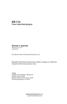
1.2.1 Overview of Logging Function
Overview
The logging function is used to record arbitrary contacts and data information together with
time stamp information at any time, and save them in an SD memory card inserted in the
CPU unit.
Log data is saved as csv format files.
Use the "Logging/Trace settings" menu of the tool software FPWIN GR7 to set the
conditions.
The settings are downloaded to the PLC as a part of project data, and stored in the ROM1.
The setting data can be saved in SD memory cards and used.
The logging operation is executed by any of those operations; (1) tool software FPWIN GR7,
(2) dedicated instructions or (3) Autostart by the setting.
To perform data logging at high speed, the buffer memory in the CPU unit is used.
Specifications
Item
Specifications
Max. number of records
1,000,000 records
Number of file
generations
Max. 2,000 generations / 1 log
Number of logs
Max. 500 devices (500 to 2,000 words) / 1 record
Remarks
Max. 1M words
Buffer memory
Can be divided into max. 16 (LOG0 to LOG15) areas
for use.
Shared with the trace
function.
Capacity per division: 8k words to 1M words
Logging start-stop
Selectable from the tool software, instructions or
autostart.
Bit device ON (Note 1)
Cycle: Hour, minute, second
Logging trigger
condition
Time: Per minute, Per hour, Every day, Every week,
Every month, Every year
Instruction: Executes an instruction with an arbitrary
condition and starts logging.
File determination
condition
(Logging stop trigger
condition)
Bit device ON (Note 2)
Time: Per minute, Per hour, Every day, Every week,
Every month, Every year
Max. number of records
Arbitrary comments can be
given.
File format
Data is saved in csv format.
(Note 1) Logging is executed when the condition is met at the end of scan.
(Note 2) Use it together with the (DF) instruction to turn ON only for one scan.
1-4
The upper limit of the
capacity on the file system
is 4 GB.
1.2 Overview of Functions
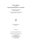
Image of logging function
FP7 CPU
Internal
memory
(RAM)
SD memory
card
Logging buffer
memory
SD
Log 0
1
Sample (130401_120100).csv
2
Sample (130401_120200).csv
3
Sample (130401_120300).csv
X
Sample (13xxxxx_xxxxxx).csv
Log1
Log 15
1-5
Overview of Functions
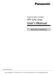
1.2.2 Overview of Trace Function
Overview
The trace function is used to record arbitrary contacts and data information together with
time stamp information in the buffer memory in the CPU unit at any time.
Logging data can be uploaded from the buffer memory to the tool software after the trace
operation, and can be displayed as a time chart. Traced data can be saved in SD memory
cards as csv format files.
When the trace stop condition is set to bit device, the operation can be stopped after logging
data of the specified number of samplings after the stop condition has been met.
Use the "Logging/Trace settings" menu of the tool software FPWIN GR7 to set the
conditions.
The settings are downloaded to the PLC as a part of project data, and stored in the ROM1.
The setting data can be saved in SD memory cards and used.
The logging operation is executed by any of those operations; (1) tool software FPWIN GR7,
(2) dedicated instructions or (3) Autostart by the setting.
Specifications
Item
Specifications
Max. number of records
1,000,000 records
Number of logs
Max. 500 devices (500 to 2,000 words) / 1 record
Remarks
Max. 1M words
Buffer memory
Can be divided into max. 16 (LOG0 to LOG15) areas
for use.
Shared with the logging
function.
Capacity per division: 8k words to 1M words
Trace start
Selectable from the tool software, instructions or
autostart.
Bit device ON (Note 1)
Trace trigger condition
Trace stop condition
Cycle: By millisecond
Instruction: Executes an instruction with an arbitrary
condition and starts trace.
Bit device ON (Note 2) (Note 3)
Buffer memory full
Arbitrary comments can be
given.
File format
Data is saved in csv format.
The upper limit of the
capacity on the file system
is 4 GB.
(Note 1) Trace is executed when the condition is met at the end of scan.
(Note 2) When selecting "Bit" for the trace stop condition, logging data of the specified number of samples is possible
after the condition is met.
(Note 3) Unlike the file determination condition of the logging function, logging of data for the specified number of
samples starts when the bit device changes from OFF to ON.
1-6
1.2 Overview of Functions
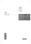
Image of trace function
The trace function can also be activated only with the internal memory of the CPU unit.
SD memory cards are used only for recording trace data in recording media.
FP7 CPU
Internal
memory
(RAM)
SD memory
card
Logging buffer
memory
1
SD
Sample (130401_120100_TRACE).csv
Log 0
Log1
Log 15
1-7
Overview of Functions
1.3 Format of Saved Files
1.3.1 File Format (For Logging Function)
Files are saved in csv format.
For the details of setting methods, refer to 2.2 Logging Information Setting.
CSV format
Time stamp information (year/month/day/hour/minute/second) and information of registered
devices are saved.
The data length varies depending on the types of specified devices.
Comments can be given at the beginning of data.
1st line
(Note 2)
2nd line
3rd line
4th line
5th line
1
2
3
-
Data name 1
Data name 2
Data name 3
-
Comment
part
Arbitrary
comment
Arbitrary
comment
Arbitrary
comment
-
(Note 1)
MOMENT
MOMENT
MOMENT
-
Data format 1
Data format 2
Data format 3
-
Unit 1
Unit 2
Unit 3
YearMonthDay
YearMonthDay
YearMonthDay
HourMinuteSecond
HourMinuteSecond
HourMinuteSecond
-
-
-
Data 1
Data 2
Data 3
Data 1
Data 2
Data 3
Data 1
Data 2
Data 3
-
-
-
-
-
-
←---------- (Note 3) -----------→
(Note 1) The contents of comment part vary depending on the settings of configuration data.
(Note 2) The number of records varies depending on the settings of file determination condition. Max. 1,000,000
records.
(Note 3) The number of data varies depending on the setting of the number of devices. Max. 500 devices
1.3.2 File Name (For Logging Function)
A file name to be saved is an arbitrary file name (date_hour-minute-second data of the first
record).
Enter a desired file name in the "Logging/Trace Settings" dialog box for each LOG number.
Example) When the file name is "Sample", and the time stamp of the first record is 12:00:00
on April 1, 2013;
Sample(130401_120000).csv
1-8
1.3 Format of Saved Files
1.3.3 File Format (For Trace Function)
Files are saved in csv format.
For the details of setting methods, refer to 2.3 Trace Information Setting
CSV format
Time stamp information (year/month/day/hour/minute/second), obtaining interval and
information of registered devices are saved.
Comments can be given at the beginning of data.
The unit for the obtaining interval is 10s. The intervals of obtaining data are saved. The
time from the previous obtainment of data is saved in the line of stop trigger (STOP TRG).
The data length varies depending on the types of specified devices.
1st line
Date
2nd line
Time
3rd line
4th line
5th line
1
2
-
Data name 1
Arbitrary
comment
MOMENT
Data name 2
Arbitrary
comment
MOMENT
-
Data format 1
Data format 2
-
Unit 1
Unit 2
-
0
Data 1
Data 2
-
Interval
Data 1
Data 2
-
Interval
Data 1
Data 2
-
Interval
STOP TRG
Interval
Data 1
-
-
Obtaining
interval
Comment
part
(Note 1)
(Note 2)
(Note 3)
YearMonthDay
YearMonthDay
YearMonthDay
YearMonthDay
YearMonthDay
-
HourMinuteSecond
HourMinuteSecond
HourMinuteSecond
HourMinuteSecond
HourMinuteSecond
-
-
Data 2
-
-
(Note 4)
(Note 1) The contents of comment part vary depending on the settings of configuration data.
(Note 2) The number of records varies depending on the settings of file determination condition. Max. 1,000,000
records.
(Note 3) The number of records after the stop trigger varies depending on the settings of configuration data.
(Note 4) The number of data varies depending on the setting of the number of devices. Max. 500 devices
1.3.4 File Name (For Trace Function)
A file name to be saved is an arbitrary file name (date_hour-minute-second data of the stop
trigger).
Enter a desired file name on the "Logging/Trace Settings" dialog box for each LOG number.
Example) When the file name is "Sample", and the time stamp of the stop trigger is 12:00:00
on April 1, 2013;
Sample(130401_120000_TRACE).csv
1-9
Overview of Functions
1.4 Data Format
The format of the data to be output as logging data and saved in a file varies according to
the type of devices.
For the details of setting methods, refer to 2.4 Registration of Device Information.
Device type and data format
Output type to files
Data type
No. of
occupied
words
Data type
No. of
characters
Range or sample
BIT
Bit data
1 word
0 or 1
1
0 or 1
US
Unsigned 16bit integer
1 word
Decimal integer
(unsigned)
5
0 to 65536
SS
Signed 16-bit
integer
1 word
Decimal integer
(signed)
6
-32768 to 32767
UL
Unsigned 32bit integer
2 words
Decimal integer
(unsigned)
10
0 to 4294967295
SL
Signed 32-bit
integer
2 words
Decimal integer
(signed)
11
-2147483648
to 2147483647
SF
Singleprecision
floating point
real number
2 words
Decimal or
exponential form
(auto)
13
-1.175494E-38
DF
Doubleprecision
floating point
real number
4 words
Decimal or
exponential form
(auto)
23
-2.2250738585072014
E-308
Hex
1 word
1 word
Hexadecimal integer
(unsigned)
4
0 to FFFF
Hex
2 words
2 words
Hexadecimal integer
(unsigned)
8
0 to FFFF FFFF
Hex
4 words
4 words
Hexadecimal integer
(unsigned)
16
0 to FFFF FFFF FFFF
FFFF
STR
String data
1-20 bytes
Character data
1 to 20 + 2
“ABCD”
(Note 1) Decimal integers (US, SS, UL, SL) and hexadecimal integers (Hex) are output in zero suppression format.
(Note 2) Decimal integers (US) are output in 5 digits when a specified decimal point output position value is 0, in 6
digits when it is 1-4, and in 7 digits when it is 5.
(Note 3) Decimal integers (SS) are output in 6 digits when a specified decimal point output position value is 0, in 7
digits when it is 1-4, and in 8 digits when it is 5.
(Note 4) Decimal integers (UL) are output in 10 digits when a specified decimal point output position value is 0, in 11
digits when it is 1-9, and in 11 digits when it is 10.
(Note 5) Decimal integers (SL) are output in 11 digits when a specified decimal point output position value is 0, in 12
digits when it is 1-9, and in 13 digits when it is 10.
(Note 6) For a signed integer (SS, SL), a sign is output at the beginning and "+" is replaced with a space.
(Note 7) Zero is added before and after decimal point by the settings of data value and decimal point output position,
and the data is output.
When device type is US and data value is "12345", the output value is "0.12345" when specifying Decimal point
5.
When device type is US and data value is "123", the output value is "0.00123" when specifying Decimal point 5.
(Note 8) Double quotation marks " " are added before and after character string data.
1-10
2
Configuration
Configuration
2.1 Definition of Buffer Memory
2.1.1 Setting Method
Setting method
Define the buffer memory of the CPU unit to be used for logging/trace.
The buffer memory is set with the tool software FPWIN GR7.
PROCEDURE
1. Define the buffer memory of the CPU unit to be used for logging/trace.
The "Logging/Trace Settings" dialog box is displayed.
2. Select a number of divisions of buffer memory from the range of 1 to 16.
3. Double-click on the field of Capacity, and input a desired capacity.
Capacity is allocated to each buffer memory.
2-2
2.1 Definition of Buffer Memory
Setting range
Item
Default
Setting range
No. of divisions of buffer memory
16
1-16
LOG0-LOG15
Buffer memory capacity (unit: k
word)
64
8-1024
2-3
Configuration
2.2 Logging Information Setting
2.2.1 Confirmation and Settings of File Information
Overview
After completing the definition of buffer memory, set the data to be logged and the format of
saved files.
File formats and logged device data are set for each buffer memory (LOG0 to LOG15).
PROCEDURE
1. Select "Tool" > "Logging/Trace Settings" in the menu bar.
The "Logging/Trace Settings" dialog box is displayed.
2. Select "File settings" in the left pane.
3. Double-click a desired buffer memory in the right pane.
The LOG 0 - LOG 15 file settings dialog box is displayed.
2-4
2.2 Logging Information Setting
LOG file settings dialog box
4. Set information in each field of File definition, Data logging condition and
File determination condition.
For the setting method, refer to the section of 2.2.2 LOG FIle Setting Items (For
Logging).
5. Press the [OK] button.
This returns to the Logging/Trace Settings dialog box.
KEY POINTS
More than one file determination condition can be set for logging
application.
Even when active logging stops, a file is determined.
For the bit device of file determination condition, select a bit which turns on
for only one scan at the end of scan.
2-5
Configuration
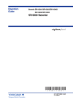
2.2.2 LOG FIle Setting Items (For Logging)
The following items are set in the LOG file settings dialog box.
Setting items
Item
File definition
Setting range
Description
File
Within 32 one-byte
characters
Enter a file name to be saved in a selected LOG number.
Application
Logging
Select Logging.
Yes: Logging operation starts when changing to the RUN
mode.
Autostart
Yes / No
File output format
CSV
Logging trigger
Bit device
No: Logging operation is started or stopped by the operation
of programming tool or the LOGST instruction/LOGED
instruction in user programs.
Select CSV.
Select a condition to start logging data.
Specify an arbitrary
bit device.
Select this for setting bit conditions as logging trigger. Press
the "Set" button, and select a device type and a number.
(Note 1)
Data logging condition
Select this for setting time as logging trigger. Input a cycle for
executing logging. (Note 2)
1 second, 2 seconds, 3 seconds, 4 seconds, 5 seconds, 6
seconds, 10 seconds, 15 seconds, 30 seconds, 1 minute, 2
minutes, 3 minutes, 4 minutes 5 minutes, 6 minutes, 10
minutes, 15 minutes, 30 minutes, 1 hour, 2 hours, 3 hours, 4
hours, 6 hours, 12 hours, 24 hours
Cycle
Time data
Time
Clock data
Select this for setting clock time as logging trigger. Specify a
time for starting logging.
Per minute, Per hour, Every day, Every week, Every month,
Every year
Instruction
-
Trigger conditions occur by executing the SMPL instruction
under arbitrary conditions in user programs.
File determination condition
Bit
Specify an arbitrary
bit device.
Select this for setting bit conditions as file determination
condition. Press the "Set" button, and select a device type and
a number.
Time
Per minute, Per
hour, Every day,
Every week, Every
month, Every year
Clock data
Select this for setting a fixed time as file determination
condition. Specify a time for determining files.
Record limit
1-1000000
No. of generations
1-2000
When max.
generation
Stop/ Continue
File write
Automatic
Select this for setting the number of records as file
determination condition. Specify the upper limit.
Set the number of generations to be saved in one file.
Stop: Stops logging.
Continue: Determines a file, and deletes the oldest file in the
PLC. After that, creates a new file.
Automatic: Once a file is determined, executes writing it into
an SD memory card.
(Note 1) For the bit device of file determination condition, select a bit which turns on for only one scan at the end of
scan.
(Note 2) When the logging trigger is cycle and setting per second or per minute, adjust to occur a tirgger at 0 min. 0
sec. of every hour. When the unit of cycle is time, adjust to occur a trigger at 00:00:00 of every day. For details,
refer to 2.5 Operation When Setting Cycle for Logging Trigger.
2-6
2.2 Logging Information Setting
Logging trigger - Trigger device settings dialog box
Set this for using bit device for the condition to start logging.
Logging trigger - Periodic trigger settings dialog box
Set this for performing logging periodically.
Logging trigger - Time trigger settings dialog box
Set this for performing logging at fixed intervals.
Logging trigger - Trigger condition setting with SMPL instruction
Specify a logging number with the dedicated instruction, and execute with an arbitrary
condition.
R200
( DF )
SMPL.US
U0
Logging trigger
n:Log no. (U0)
n
2-7
Configuration
2.3 Trace Information Setting
2.3.1 Confirmation and Settings of File Information
The following items are set in the LOG file settings dialog box.
Overview
After completing the definition of buffer memory, set the data to be traced and the format of
saved files.
File formats and traced device data are set for each buffer memory (LOG0 to LOG15).
PROCEDURE
1. Select "Tool" > "Logging/Trace Settings" in the menu bar.
The "Logging/Trace Settings" dialog box is displayed.
2. Select "File settings" in the left pane.
2-8
2.3 Trace Information Setting
3. Double-click a desired buffer memory in the right pane.
The LOG 0 - LOG 15 file settings dialog box is displayed.
4. Set information in each field of File definition, Data logging condition and
Trace stop.
For the setting method, refer to the section of 2.3.2 LOG FIle Setting Items (For
Trace).
5. Press the [OK] button.
This returns to the Logging/Trace Settings dialog box.
KEY POINTS
"No. of samplings after stop trigger" is available only when the stop trigger
is set to Bit.
Check the box of "Write file after completion of trace" to create a file in an
SD memory card after the completion of trace.
2-9
Configuration
2.3.2 LOG FIle Setting Items (For Trace)
The following items are set in the LOG file settings dialog box.
Setting items
File definition
Item
Setting range
Description
File
Within 32 one-byte
characters
Enter a file name to be saved in a selected LOG number.
Application
Trace
Select Trace.
Autostart
Yes / No
File output format
CSV
Yes: Trace operation starts when changing to the RUN mode.
Logging trigger
Data logging condition
Bit device
No: Trace operation is started by the operation of
programming tool or the LOGST instruction in user programs.
Select CSV.
Select a condition to start logging data.
Specify an arbitrary
bit device.
Select this for setting bit conditions as logging trigger. Press
the "Set" button, and select a device type and a number.
Select this for setting time as logging trigger. Input a cycle for
executing trace.
Cycle
Time data
Instruction
-
1 second, 2 seconds, 3 seconds, 4 seconds, 5 seconds, 6
seconds, 10 seconds, 15 seconds, 30 seconds, 1 minute, 2
minutes, 3 minutes, 4 minutes 5 minutes, 6 minutes, 10
minutes, 15 minutes, 30 minutes, 1 hour, 2 hours, 3 hours, 4
hours, 6 hours, 12 hours, 24 hours
Trigger conditions occur by executing the SMPL instruction
under arbitrary conditions in user programs.
Stops Trace.
Trace stop condition
2-10
Bit
Press the "Set" button to specify a device type, a number and
the number of samplings after the detection of stop trigger.
Buffer full
Trace operation stops once the buffer is full.
No. of samplings
after stop trigger
detection
0-262144
Specify the number of samplings after the detection of stop
trigger.
File write
Automatic
On completion of trace operation, executes writing data into
an SD memory card.
Stop trigger
2.3 Trace Information Setting
Logging trigger - Trigger device settings dialog box
Set this for using the leading edge of bit device for the condition to start trace.
Logging trigger - Periodic Trigger settings dialog box
Set this for performing trace periodically. When selecting Trace for Application, it can be
specified in msec.
Logging trigger - Trigger condition setting with SMPL instruction
Specify a logging number with the dedicated instruction, and execute with an arbitrary
condition.
R200
( DF )
SMPL.US
U0
Logging trigger
n:Log no. (U0)
n
2-11
Configuration
2.4 Registration of Device Information
Overview
Devices on which logging/trace is performed are registered in "Register logging devices".
PROCEDURE
1. Select a desired LOG number for a logging device in the left pane.
2. Double-click on the line of a desired number in the right pane.
The "Register devices" dialog box is displayed.
3. Enter a desired device number and comments, and press the [OK] button.
The device on which logging is performed is registered in the LOG number.
4. Repeat the registration of devices for each LOG number.
KEY POINTS
2-12
The number of devices that can be registered in one LOG number is up to
500 devices.
Press the [INS] key to insert items in the device list, and press the [DEL] key
to delete them.
2.4 Registration of Device Information
Setting items ("Register devices" dialog box)
Item
Setting range
Description
Device
Global devices
Local devices
In case of local devices, specify a PB number.
Slot No.
1-16
Specify a slot number when specifying IN, OT, WI, WO
or UM for the device type.
X、Y、R、L、T,C、P、SR、IN、
OT、DT,n、LD,n、
Device type
Data logging conditions of devices
No.
WX、WY、WR、WL、WS、IN、
OT、DT、LD、SD、WI、WO、
UM、、TS、TE、CS、CE、I
Device number
Specify a device type to be logged.
Specify a device number to be logged.
Bit data
Data type
16-bit unsigned integer
16-bit signed integer
32-bit unsigned integer
32-bit signed integer
Single-precision real number
Double-precision real number
HEX 1 word
HEX 2 words
HEX 4 words
Character string
Specify a data format to be output. The settable range
varies according to the number of selected devices.
Comment
registration
Decimal point
position
0-11
The position of decimal point can be set when an
integer type is selected for Data type. The settable
range varies according to the selected data type.
No. of
continuous
registrations
1 to max. 500
Input a number for specifying the same type of devices
all at once. The settable range varies according to the
number of selected devices.
Arbitrary
Within 32 one-byte characters
Output to the comment area when saving data in CSV
format.
Data name
Arbitrary
application
Unit
2-13
Configuration
2.5 Operation When Setting Cycle for Logging Trigger
When setting Cycle for logging triggers, the time of the first trigger is adjusted to perform
subsequent logging at good timing.
When the unit of cycle is second or minute, adjust to occur a tirgger at 0 min. 0 sec. of every
hour.
When the unit of cycle is time, adjust to occur a trigger at 00:00:00 of every day.
Example of timing of trigger occurrence (when the unit of cycle is second)
Time at which
logging trigger
condition is met
Set cycle
Time at which the 1st
trigger occurs after
adjustment
Time at which subsequent
triggers occur
12:01:05
12:01:05
1 second
12:01:06
12:01:07, 12:01:08
2 seconds
12:01:06
12:01:08, 12:01:10
12:01:05
3 seconds
12:01:06
12:01:09, 12:01:12
12:01:05
4 seconds
12:01:08
12:01:12, 12:01:16
12:01:05
5 seconds
12:01:10
12:01:15, 12:01:20
12:01:05
10 seconds
12:01:10
12:01:20, 12:01:30
12:01:05
15 seconds
12:01:15
12:01:30, 12:01:45
12:01:05
30 seconds
12:01:30
12:02:00, 12:02:30
Example of timing of trigger occurrence (when the unit of cycle is minute)
Time at which
logging trigger
condition is met
Set cycle
Time at which the 1st
trigger occurs after
adjustment
12:01:00
1 minute
12:02:00
12:03, 12:04, 12:05
12:03:00
2 minutes
12:04:00
12:04, 12:06, 12:08
12:05:00
3 minutes
12:06:00
12:09, 12:12, 12:15
12:05:00
4 minutes
12:08:00
12:12, 12:16, 12:20
12:05:00
5 minutes
12:10:00
12:15, 12:20, 12:25
12:01:00
10 minutes
12:10:00
12:20, 12:30, 12:40
12:59:00
15 minutes
13:00:00
13:15, 13:30, 13:45
12:10:00
30 minutes
12:30:00
13:00, 13:30, 14:00
Time at which subsequent
triggers occur
Example of timing of trigger occurrence (when the unit of cycle is hour)
Time at which
logging trigger
condition is met
Set cycle
Time at which the 1st
trigger occurs after
adjustment
Time at which subsequent
triggers occur
12:59:00
1 hour
13:00:00
14, 15, 16 o'colock ...
12:59:00
2 hours
14:00:00
16, 18, 20 o'colock ...
12:30:00
3 hours
15:00:00
18, 21, 24 o'clock ...
12:30:00
4 hours
16:00:00
20, 24, 28 o'clock ...
12:30:00
6 hours
18:00:00
24, 30, 36 o'colock ...
12:30:00
12 hours
24:00:00
36, 48, 60 o'clock ...
12:30:00
24 hours
24:00:00
48, 72, 96 o'clock ...
2-14
2.6 Downloading Setting Data to CPU Unit
2.6 Downloading Setting Data to CPU Unit
2.6.1 Downloading to Execution Memory RAM/ROM1
Overview
Parameters set in the logging/trace settings menu are downloaded together with programs
and configuration data as project data.
2.6.2 Copying from SD Memory Card to Execution Memory RAM/ROM1
Overview
Logging/trace settings auto-run files are copied to the memory RAM/ROM1 for program
execution via SD memory cards.
PROCEDURE
1. Create an "AUTO" folder in an SD memory card.
2. Select "Tool" > "SD Memory Card" > "Create Logging/Trace Settings AutoRun File" in the menu bar.
The "Create auto-run file" dialog box is displayed.
3. Select "Create new settings" and LOG numbers, and press the [Yes] button.
The "Browse Folders" dialog box is displayed.
4. Select a desired folder, and press the [Yes] button.
A logging/trace settings auto-run file "logtrc.fp7" is created.
5. Save the created file in the "AUTO" folder in the SD memory card.
6. Insert the SD memory card into the CPU unit.
7. Set the mode switch of the CPU unit to the "COPY" (right-hand side) until
the SD LED and COPY LED flashes.
The logging/trace settings auto-run file "logtrc.fp7" is copied into the execution
memory RAM/ROM1.
2-15
Configuration
2.6.3 Saving to SD Memory Card (In SD Memory Card Operation)
Overview
To perfrom SD memroy card operation, write a file for automatic start in an SD memory card.
Create the setting file in the following procedure.
PROCEDURE
1. Create an "AUTO" folder in an SD memory card.
2. Select "Tool" > "SD Memory Card" > "Create Logging/Trace Settings AutoRun File" in the menu bar.
The "Create auto-run file" dialog box is displayed.
3. Select "Create new settings" and LOG numbers, and press the [Yes] button.
The "Browse Folders" dialog box is displayed.
4. Select a desired folder, and press the [Yes] button.
A logging/trace settings auto-run file "logtrc.fp7" is created.
5. Save the created file in the "AUTO" folder in the SD memory card.
6. Insert the SD memory card, in which the logging/trace settings auto-run file
"logtrc.fp7" is written together with the auto-run file "autoexec.fp7", into the
CPU unit.
7. Set the mode switch to the SD side, and execute the operation.
KEY POINTS
2-16
The logging/trace settings are saved in the non-volatile memory ROM1 in
the CPU unit as a part of project data. However, they are not saved in the
non-volatile memory ROM during the SD memory card operation.
2.7 Precautions on Downloading Setting Data
2.7 Precautions on Downloading Setting Data
2.7.1 Storage of Setting Data
Downloaded data is stored in the non-volatile memory in the PLC, and held until it is deleted
or re-registered.
2.7.2 Project Data Consistency
Use the logging/trace setting data created in the project to be executed. The logging/trace
settings created in a different project from the executed project may not be activated. Be
careful when downloading only the logging/trace settings or loading/copying them from an
SD memory card.
When there is an inconsistency in project data, the error code (81) is returned, and the data
cannot be downloaded from a PC.
When there is an inconsistency in loading data form an SD memory card, the self-diagnostic
error (125) is reported.
2.7.3 Autostart Setting
When "Autostart" has been selected in 2.2 the "LOG file settings" dialog box, the
logging/trace operation starts immediately after the mode is switched to the RUN mode.
2-17
Configuration
2-18
3
Start-Stop and Monitor
Start-Stop and Monitor
3.1 Start and Stop of Logging/Trace Operation
3.1.1 Start and Stop with Tool Software
Overview
The logging/trace operation can be started and stopped with the tool software.
PROCEDURE
1. Select "Tool" > "Logging/Trace Monitor" in the menu bar.
The "Logging/Trace Monitor" dialog box is displayed.
2. Check the box of a desired LOG number, and press the [Start] button.
A confirmation message is displayed.
3. Press the [Yes] button.
Starting the logging operation is requested by the operation specified in the
"Logging/Trace Settings" dialog box. System relays relating to the execution of
logging/trace can be monitored in the above dialog box. Once the operation is
started normally, the "logging/trace active" and "SD card logging/trace active"
flags turn on.
4. For stopping the logging/trace operation, check the box of a desired LOG
number and press the [Stop] button.
Stopping the logging/trace operation is requested. Once the logging/trace
operation ends normally, the "logging/trace done" flag turns on.
3-2
3.1 Start and Stop of Logging/Trace Operation
3.1.2 Start and Stop with Instructions
Overview
The logging/trace operation can be started and stopped with user programs for each
logging/trace number.
Specify a logging/trace number (0 to 15) with the dedicated instruction, and execute with
arbitrary conditions.
R100
( DF )
LOGST.US
U0
Logging start request
n:Log no. (U0)
n
R101
( DF )
LOGED.US
U0
Logging stop request
n:Log no. (U0)
n
It takes a few milliseconds to a few seconds to start or stop the logging/trace operation.
For stopping the logging/trace operation with instructions, request the stop after confirming
that the active flags (SR100, SR101) turn on. If requesting to stop LOG n during start
operation, the operation error flags (SR7, SR8) or the logging/trace error flag (SR105) turn
on.
For starting the logging/trace operation with instructions, request the start after confirming
that the logging/trace done flag (SR102) turns on. If requesting to start LOG n during stop
operation, the operation error flags (SR7, SR8) or the logging/trace error flag (SR105) turn
on.
There is no problem if a start request is made for LOG n during startup or in startup
processing.
There is no problem if a stop request is made for LOG n that stops or in stop processing.
3.1.3 Autostart by Setting
When "Autostart" has been selected in the "LOG file settings" dialog box, the start request of
the logging/trace operation is made immediately after the mode is switched to the RUN
mode.
NOTE
The trace operation stops when the trace stop condition (bit device ON or
buffer full) is met. If the operation is forcibly stopped with the tool software
or instruction while the trace stop condition has not been satisfied, the
trace operation is cancelled and the data is not saved.
3-3
Start-Stop and Monitor
3.2 Operation Check Using Logging/Trace Monitor
3.2.1 Logging/Trace Monitor
The progress situation can be confirmed with the logging/trace monitor.
Example of monitoring in logging operation
Example of monitoring on the completion of trace operation
3-4
3.2 Operation Check Using Logging/Trace Monitor
3.2.2 System Relays Relating to Logging/Trace Operation
System relays
Device
No.
Name
Operation
Turns on during the startup of logging/trace operation. Another system
relay allocated to the same LOG number is reset during the start operation.
SR100
Logging trace
active
SR101
SD card logging
active
Turns on when writing files into an SD memory card becomes enabled
after turning on the logging/trace active relay and enabling logging in the
buffer. This relay is always off when selecting Trace for the application.
SR102
Logging trace
done
Turns on after the completion of the stop request for logging/trace or the
completion of file writing at the time of automatic stop.
SR103
Logging overspeed relay
The logging/trace function is activated by any of the following methods; 1:
Autostart setting, 2: Start by instructions, 3: Start by the tool software.
Storing data in the buffer is executed while this relay is on.
Turns on when the buffer logging speed exceeds the writing speed to an
SD memory card in logging operation. Turns on when the number of data
previously stored and the number of data stored this time increase.
Turns on at the timing of buffer logging, and turns off at the timing of buffer
logging or the end of scan.
Turns on when the buffer has been exhausted. The buffer overflow
counters (SD120-SD135) are incremented (+1). At that time, new data
cannot be stored. Also, writing data into the SD memory card does not stop.
SR104
Buffer overflow
relay
The buffer overflow relay turns off at the end of scan when a vacancy
occurs in the buffer as writing data into an SD memory card progresses, and
the buffer overflow counter is cleared to 0. Also, after the occurrence of
buffer vacancy, data logging is executed once the logging trigger condition is
met.
This relay is always on when buffer full occurs as the stop condition when
selecting Trace for the application.
SR105
Logging/trace
error
Turns on when an error is detected during the logging/trace operation and
stops logging/trace.
SR106
No SD card free
space
Turns on when an SD memory card is running out of free space during the
logging/trace operation and stops logging/trace.
SR107
Device and
trigger setting
error
Turns on when an error is detected in set values during the startup
operation. The logging/trace error relay SR105 also turns on. At that time,
the active relay does not turn on because the logging/trace function cannot
be activated.
SR108
Tracing stop
trigger monitor
Monitors a registered trace stop trigger when executing tracing. Turns on
when conditions are met. This relay is always off when selecting Logging for
the application.
SR109
Trace data
acquisition done
Turns on after logging data for a specified number of times after detecting
the trace stop trigger during the execution of trace. This relay is always off
when selecting Logging for the application.
(Note 1) The above device numbers are those for LOG0. System relay numbers vary depending on LOG numbers as
shown in the table below.
LOG
0
1
2
3
4
5
6
7
8
9
10
11
12
13
14
15
No.
100 110 120 130 140 150 160 170 180 190 200 210 220 230 240 250
SR
to
to
to
to
to
to
to
to
to
to
to
to
to
to
to
to
No.
109 119 129 139 149 159 169 179 189 199 209 219 229 239 249 259
3-5
Start-Stop and Monitor
3.2.3 System Data Registers Relating to Logging/Trace Operation
System data registers (SD)
Device
No.
Name
Operation
SD100
Buffer free space
Stores free space of buffer memory during logging. This relay is always
zero when selecting Trace for the application.
SD120
Buffer overflow
counter
Increments the value (+1) when the buffer overflow occurs. This is always
zero when selecting Trace for the application.
(Note 1) The above device numbers are those for LOG0. System data register numbers vary depending on LOG
numbers as shown in the table below.
LOG
0
1
2
3
4
5
6
7
8
9
10
11
12
13
14
15
No.
100 101 102 103 104 105 106 107 108 109 110 111 112 113 114 115
SD
No.
120 121 122 123 124 125 126 127 128 129 130 131 132 133 134 135
3.2.4 Checking Logging Speed (When Selecting Logging For Application)
When the logging speed to the buffer memory of the CPU unit is faster than the writing
speed into an SD memory card, the logging over-speed relay turns on. The logging overspeed relay turns on at the timing of logging trigger, and turns off if the speed does not
exceed at the end of scan.
If overspeed occurs frequently, the buffer memory will be full and data cannot be
accumulated.
Once the buffer memory is full, the buffer overflow flag turns on, and the buffer overflow
counter is incremented (+1).
If the buffer overflow occurs continuously, revise the logging conditions to decrease the
logging speed.
To know how much logging data was lost at the time of buffer overflow, register the buffer
overflow counter as logging data.
Even if the buffer overflow occurs, recording data into an SD memory card goes on, and
logging continues when free space becomes available in the buffer.
The free space of buffer memory can be checked with the system data registers SD100 to
SD115.
The system relays (SR104, SR114, SR124 ...) give a warning when the buffer memory is full.
3-6
3.3 Operation Check Using System Monitor
3.3 Operation Check Using System Monitor
3.3.1 Monitoring Method of System Monitor Area (SM)
By using the system monitor function, the number of written records in a current file, the
number of files stored in a folder (number of generations) and the oldest clock data of files
stored in the folder can be monitored.
The system monitor area can be monitored with the tool software FPWIN GR7.
PROCEDURE
1. Select "Online" > "Display System Monitor Area (SM)" in the menu bar.
The system monitor dialog box is displayed.
2. Press the [Refresh] button.
The latest information is read.
3.3.2 List of System Monitor Area (SM)
SM211-SM258: Logging/Trace information
SM No.
Name
211-212
For LOG0
213-214
For LOG1
215-216
For LOG2
217-218
For LOG3
219-220
For LOG4
221-222
For LOG5
223-224
For LOG6
225-226
For LOG7
227-228
For LOG8
229-230
For LOG9
231-222
For LOG10
233-224
For LOG11
235-226
For LOG12
237-228
For LOG13
239-240
For LOG14
241-242
For LOG15
No. of written
records of current
file
Description
Stores the number of written records in
a current file as 32-bit data.
One is added every time a file is written,
and it is reset to zero when a new file is
created.
3-7
Start-Stop and Monitor
SM No.
Name
243
For LOG0
244
For LOG1
245
For LOG2
246
For LOG3
247
For LOG4
248
For LOG5
249
For LOG6
250
For LOG7
251
For LOG8
252
For LOG9
253
For LOG10
254
For LOG11
255
For LOG12
256
For LOG13
257
For LOG14
258
For LOG15
259-260
For LOG0
261-262
For LOG1
263-264
For LOG2
265-266
For LOG3
267-268
For LOG4
269-270
For LOG5
271-272
For LOG6
273-274
For LOG7
275-276
For LOG8
277-278
For LOG9
279-280
For LOG10
281-282
For LOG11
283-284
For LOG12
285-286
For LOG13
287-288
For LOG14
289-290
For LOG15
3-8
Description
No of files
(generations)
stored in folder
Stores the number of files stored in a
folder (number of generations) as 16-bit
data.
Oldest clock data
of file stored in
folder
Stores the oldest clock data of a file
stored in a folder as 32-bit data by
seconds.
4
Logging Operation
Logging Operation
4.1 Flow of Logging Operation
4.1.1 Operation Flow
Triggers of logging operation and file contents
STEP
1
2
Operation
Start
Logging
Trigger of
operation
File in LOG folder
File contents
Bit device ON
Cycle
Instruction
Time
Sample(------current------).csv”
Comment file part
First record
Bit device ON
Cycle
Instruction
Time
Sample(------current------).csv”
Comment file part
First record
Second record
Tool software
operation
Instruction
Autostart setting
Logging operation continues until the file determination condition is met.
3
2
File
determinatio
n
Logging
Bit device ON
Time
Record limit
Bit device ON
Cycle
Instruction
Time
Sample(130401_120000).csv”
Comment file part
First record
Second record
・・・・・・・・・・・・・・・・・
Sample(------current------).csv”
Comment file part
Sample(------current------).csv”
Comment file part
First record
Logging operation continues until the file determination condition is met.
3
File
determinatio
n
2
Logging
Bit device ON
Time
Record limit
Sample(130401_120000).csv”
Sample(130401_130000).csv”
Sample(------current------).csv”
Comment file part
First record
Second record
・・・・・・・・・・・・・・・・・
Comment file part
Logging, file determination, and logging operation continues until the stop condition is met.
Sample(130401_120000).csv”
4
4-2
Stop
Tool software
operation
Instruction
Max. file generation
Sample(130401_130000).csv”
Sample(130401_140000).csv”
Comment file part
First record
Second record
・・・・・・・・・・・・・・・・・
Comment file part
・・・・・・・・・・・・・・・・・
(Records up to stop)
・・・・・・・・・・・・・・・・・
4.1 Flow of Logging Operation
Flow of logging operation
STEP 1: Startup of logging operation
The logging operation is started by any of the following methods; Tool software operation,
Instruction in a user program, and Autostart setting.
STEP 2: Data logging
After the startup of logging operation, logging data is executed with a specified condition
once the specified trigger condition (bit device ON, cycle, or time) is met.
A LOG folder is created in an SD memory card for the LOG number that a file name is set.
A file "specified file name (------current------).csv" for saving logging data is created in the
LOG folder.
Logged data is stored in the logging buffer memory (RAM) in the CPU unit once, and they
are automatically written into files in an SD memory card by the CPU unit. It is not necessary
to write them using user programs.
After that, the CPU unit continues saving data into the same file until the file determination
condition is met.
STEP 3: File determination
A file is determined when the specified file determination condition (bit device ON, time,
record limit) is met.
The file determination is to rename the file "specified file name (------current------).csv"
created in STEP 2 after writing all the data stored in the buffer into the SD memory card.
The time data of the oldest record is added to the specified file name.
Example) When the file name is Sample, and the oldest record was recorded in 12 o'clock
on April 1, 2013, it is saved as "specified file name (130401_120000).csv".
Once the file is determined, a new file "specified file name (------current------).csv" for saving
the next logging data is created. The logging operation restarts when the logging trigger
condition is met.
STEP 4: Stop of logging operation
The logging operation is stopped by either of instruction in user programs or tool software
operation.
Once the logging operation stop is requested, all the data in the buffer memory in the CPU
unit is written into the file in the SD memory card and determined. When the logging
operation is conitnuing, the records logged so far are saved and the file is determined even if
the specified file determination condition has not been satisfied.
The time data of the oldest record is added to the specified file name.
KEY POINTS
When the logging trigger setting is "Bit, Cycle or Time", the buffer memory
data is stored at the end of the scan time. In the case of Instruction, it is
stored when the SMPL instruction is executed.
4-3
Logging Operation
4.2 Operation When Logging is Selected for Application
4.2.1 Operation When Logging Operation Starts
The following operations are executed when the start operation is requested.
Registered data is confirmed.
Once the logging/trace becomes executable, the logging/trace active flags (SR100, SR110,
SR122 ...) turn on. When the logging trigger condition is met under this condition, the
logging/trace operation starts.
All other flags than the logging/trace active flag for LOG n are cleared during the start
request operation.
Once writing data into an SD memory card becomes enabled after the logging/trace active
flags (SR100, SR110, SR122 ...) turned on, the SD card logging active flags (SR101, SR111,
SR112 ...) turn on.
When an SD memory card that can be normally read and written is not inserted, or the card
cover is open, an operation error occurs.
4.2.2 Operation When Logging Operation Stops
Operation when switching from RUN mode to PROG. mode
All logging operations stop.
All information saved in the buffer memory of the CPU unit is written into a file, and the file is
determined.
4.2.3 Operation When Power Supply Turns Off
Operation when power supply turns off
When activating logging/trace, the power off flag during file access SR3F turns on..
The data stored in the logging buffer of the CPU unit is discarded.
NOTE
4-4
In case of the middle of file writing, written data or files may be damaged, or
the SD memory itself may not be read.
4.2 Operation When Logging is Selected for Application
4.2.4 Operation When the Card Cover of CPU Unit Opens
The following operations are performed when the card cover is open during the logging
operation.
Operation of system relays
The logging/trace active flag and the SD card logging active flag stays on while the card
cover is open.
Although the logging/trace active flag turns off once the logging stop condition is met, the SD
card logging active flag stays on.
When the card cover is closed, the SD card logging active flag also turns off.
The logging operation into the logging buffer (RAM) continues even when no SD memory
card is inserted. Once the logging buffer (RAM) becomes full, the buffer overflow flag turns
on.
File status in SD memory card
The file "specified file name (------current------).csv" in which logging data was saved before
opening the cover is held in the SD memory card.
Once the card cover is closed, the saving into files starts again.
4-5
Logging Operation
4.2.5 Operation When the Number of Determination Files Reaches the
Maximum Number of Generations
Operation when the number of determination files reaches the maximum number of
generations
The operation when the number of determination files reaches the maximum number of
generations varies depending on the log file settings.
File determination
condition
When max.
generation
Stop
Operation
1) Determines a current file "specified file name (------current------).csv", gives the time
data of the oldest record, and renames it.
2) Creates a new current file "specified file name (------current------).csv".
1) Determines a current file "specified file name (------current------).csv", gives the time
data of the oldest record, and renames it.
Continue
2) Deletes the oldest file.
After deleting it, updates the data of the oldest file displayed in the system monitor area
(SM).
3) Creates a new current file "specified file name (------current------).csv".
"Logging File Settings" dialog box
4-6
4.3 System Management Information Relating to Logging Function
4.3 System Management Information Relating to Logging
Function
4.3.1 System Management Information and Operation
The PLC manages files as follows. So, the PLC performs operations based on the stored
management information even if an SD memory card is removed during logging, and
another SD memory card in different conditions from the conditions managed in the PLC is
inserted.
Writing data into an undetermined file "specified file name (------current------).csv" is executed
every time specified records are stored. The number of written records can be confirmed in
the system monitor area (SM212 to SM242).
The number of generations of determined files is managed during the logging operation. The
number of determined files can be confirmed in the system monitor area (SM243 to SM258).
The determined date is managed in the internal memory at the time of file determination, and
the time data of the oldest file is stored in the system monitor area (SM259 to SM290).
4.3.2 Clearing Management Information
Clearing management information
Log file management information of the PLC is cleared in the following cases.
When LOG n settings are deleted or all log settings are initialized from the tool software
FPWIN GR7
When a buffer allocation different from stored data is downloaded, all log settings are
initialized.
When a LOGn definition different from stored data is downloaded, only the different LOG n is
cleared.
KEY POINTS
If the above clearing operation is performed, log file management
information is initialized, and files remained in the SD memory card are
regarded as non-existent. Delete files beforehand, and use it.
When restarting logging with the same condition without changing setting
information, the operation continues with the previous system information,
the number of generations (SM243 to SM258) and the oldest time data of the
file (SM259 to SM290). After restarting logging, the number of generations is
added to the data before the restart, and the existing value is held for the
oldest time data.
4-7
Logging Operation
4-8
5
Trace Operation and Time
Chart
Trace Operation and Time Chart
5.1 Flow of Trace Operation
5.1.1 Operation Flow
Triggers of trace operation and file contents
STEP
1
Operation
Start
Trigger of
operation
File in LOG folder
File contents
Tool software
operation
Instruction
Autostart setting
Bit device ON
Cycle
Instruction
2
Logging
Bit device ON
Cycle
Instruction
Logging operation continues until the trace stop condition is met.
Trace stop
When buffer full is set
for stop trigger
Sample
(130401_120000_TRACE).csv”
Comment file part
First record
Second record
・・・・・・・・・・・・・・・・・
STOP TRG
When bit device ON
is set for stop trigger
Sample(------current------).csv”
Comment file part
First record
Second record
・・・・・・・・・・・・・・・・・
STOP TRG
3
Logging operation continues for the number of smplings after the dtection of stop
trigger.
Trace stop
Completion of logging
for the number of
samplings
Sample
(130401_120030_TRACE).csv”
Comment file part
First record
Second record
・・・・・・・・・・・・・・・・・
STOP TRG
・・・・・・・・・・・・・・・・・
XXX records
5-2
5.1 Flow of Trace Operation
Flow of trace operation
STEP 1: Startup of trace Operation
The trace operation is started by any of the following methods; Tool software operation,
Instruction in a user program, and Autostart setting.
STEP 2: Data logging
After the startup of the trace operation, tracing data is executed with a specified condition
when the specified trigger condition (bit device ON, cycle, or instruction) is met.
Traced data is stored in the logging buffer memory (RAM) in the CPU unit.
After that, the trace operation continues until the trace stop condition is met.
STEP 3: Stop of trace Operation
The trace operation stops when either condition is met, bit or buffer full.
When the trace stop condition is bit, the trace operation stops after the logging performed for
the specified number of samplings after the condition was met.
When the trace stop condition is buffer full, the trace operation stops immediately.
When the trace operation is complete successfully, the trace data acquisition done flags
(SR109, SR119 ...) turn on. At that time, a time chart can be displayed on the programming
tool FPWIN GR7 by reading the logged data.
When "Write file after completion of trace" is set, all the data in the buffer memory in the
CPU unit is written into the file in the SD memory card and determined. The time stamp
information is the time data at the time of the occurence of stop trigger.
KEY POINTS
In the data logging process into the buffer memory, when Bit or Cycle has
been specified, the bit or the cycle is checked at the end of scan, and data
is stored in the buffer memory when the condition is met. When Instruction
has been set, data is stored into the buffer memory when the instruction is
executed.
If the trace operation is stopped by the tool software operation or the
LOGED instruction while the trace stop condition has not been met, logged
data is not saved in either the buffer memory (RAM) or an SD memory card.
5-3
Trace Operation and Time Chart
5.2 Operation When Trace is Selected for Application
5.2.1 Operation When Trace Operation Starts
The following operations are executed when the start operation is requested.
Registered data is confirmed.
The logging/trace active flags (SR100, SR110, SR120 ...) turn on.
All other flags than the logging/trace active flag for LOG n are cleared during the start
request operation.
Once writing data into an SD memory card becomes enabled after the logging/trace active
flags (SR100, SR110, SR122 ...) turned on, the SD card logging active flags (SR101, SR111,
SR112 ...) turn on.
When the box of "Write file after completion of trace" has been checked in the LOG file
settings dialog box, an operation error occurs if no SD memory card that is normally
readable and writable is inserted, or the card cover is open.
5.2.2 Operation When Logging Operation Stops
Operation when switching from RUN mode to PROG. mode
All logging operations stop.
The data stored in the buffer memory of the CPU unit is discarded.
5.2.3 Operation When Power Supply Turns Off
Operation When Power Supply Turns Off
When activating logging/trace, the power off flag during file access SR3F turns on.
The data stored in the logging buffer (RAM) of the CPU unit is discarded.
NOTE
5-4
In case of the middle of file writing into an SD memory card, written data or
files may be damaged, or the SD memory itself may not be read.
5.2 Operation When Trace is Selected for Application
5.2.4 Operation When the Card Cover of CPU Unit Opens
The following operations are performed when the card cover is open during the trace
operation.
Operation of system relays
The logging/trace active flag and the SD card logging active flag stays on while the card
cover is open.
Although the logging/trace active flag turns off once the trace stop condition is met, the SD
card logging active flag stays on.
When the card cover is closed, the SD card logging active flag also turns off.
The logging operation into the logging buffer (RAM) continues even when no SD memory
card is inserted. Once the logging buffer (RAM) becomes full, the buffer overflow flag turns
on.
File status in SD memory card
If data cannot be written into an SD memory card after the completion of trace, the
logging/trace error flag turns on, and the operation ends.
5-5
Trace Operation and Time Chart
5.3 Trace Monitor (Time Chart)
5.3.1 Display Method of Time Chart
Overview
Time chart is a function to read the data stored in the PLC using the trace function and
display them in graph form.
By setting the trace function, the change in contacts/data can be checked by one scan.
PROCEDURE
1. Select "Tool" > "Logging/Trace Monitor" in the menu bar.
The "Logging/Trace Monitor" dialog box is displayed.
2. Check the box of one LOG number, and press the [Time Chart] button.
The trace data is read from the PLC, and the time chart is displayed.
5-6
5.3 Trace Monitor (Time Chart)
KEY POINTS
The following conditions are required to display a time chart.
-
Only one LOG number is selected.
The target LOG is set to "Trace".
The logging/trace done flag of the target LOG is "ON".
When the stop tirgger is detected, the "Trace stop trigger monitor flag"
and "Trace data acquisition done flag" turn on.
The time chart cannot be activated during executing the logging/trace
operation.
The indication of the "Buffer free space" of the LOG that has been set to
Trace is always zero.
5-7
Trace Operation and Time Chart
5.3.2 Explanation of Time Chart Monitor
The time chart window is composed of the following parts.
C-1
B-3
A-1
A-2
B-1
A-3
B-2
Names and functions of parts
Mark
A-1
A-2
Name
Trace data display area
(All devices)
Function
Displays the devices registered in the target LOG for the time chart
display.
・Select the device to be displayed in graphs from this list.
・Corrensponding data is displayed at the position of the cursor [C] or [R]
in the graph display area (B-1).
Trace data display area
・Contact data selected in A-1 is displayed in this area.
(Contact devices)
・When a lot of devices are registered, a scroll bar is displayed.
・Data other than the contact data selected in A-1 is displayed in this area.
A-3
B-1
B-2
Trace data display area
・Up to six data can be displayed in this area.
(Data devices)
・Pressing the button which displays a deivce name can change the line
color.
Graph display area
Time display area
・Displays trace data as line graphs in chronological order. (The on/off
state of contacts is displayed with rectangular wave form.)
・The vertical line with a [T] mark is displayed at the point where a trigger
occurs.
Displays the time between arbitrary two points or the time between the
point where a trigger occurs and an arbitrary point using the two cursors
[C] and [R] in B-1.
However, time is not displayed when the selected trigger type is other
than "Constant period".
・Displays the number of samplings and sampling rate.
B-3
Trace information display
area
・The sampling rate is displayed by time unit when the logging trigger is
"Constat period".
When the logging trigger is "Bit" or "Instruction", this area is not available.
(A hyphen is displayed.)
5-8
5.3 Trace Monitor (Time Chart)
Mark
Name
Function
Graph Option button
C-1
Magnify
・Enlarges graphs by pressing the button. (The values of the time scale
become small.) Desired parts can be confirmed closely.
Reduce
Reduces graphs by pressing the button. (The values of the time scale
become large.) This is used to see the whole area.
Back
Closes the time chart and returns to the logging/trace monitor screen by
pressing this button.
Graph Option
Field name
Scale
Contact
display
Function
Range
Specify the display range of the vertical axis of a graph.
No. of decimal digits
Specify the number of decimal places for the vertical axis.
Set the number of
contacts.
Fix the number of contacts to be displayed in graphs.
The height of displayed contacts varies depending on the resolution of the
display.
Set the height of
contacts.
Fix the height of the display of contacts. (Unit is dot.)
The higher the display resolution becomes, the more contacts can be
displayed.
Background color
Select the background color of the graph.
KEY POINTS
The time display area is available only when the logging trigger is "Constant
period". This area is not displayed when the logging trigger is "Bit" or
"Instruction".
5-9
Trace Operation and Time Chart
5.3.3 Restrictions on Time Chart Monitor
The restrictions on the time chart are as follows.
Although a maximum of 16 patterns of trace can be executed (in the case all LOGs are
operated for trace application), only one LOG can be displayed on the time chart.
A maximum of 500 devices can be registered for one LOG, however, there are restrictions
on devices to be graphically displayed on the time chart.
・In case of contact device: According to the resolution of a display
・In case of data devices: Up to six devices
Time cannot be measured with the cursors (C, R) on graphs when the LOG displayed as a
time chart is the data that was traced with logging triggers other than constant period.
5-10
6
Troubleshooting
Troubleshooting
6.1 Operations When Errors Occur
6.1.1 Operation When Power Supply Turns Off
Operation when power supply turns off
When activating logging/trace, the power off flag during file access SR3F turns on.
The data stored in the buffer of the CPU unit is discarded.
NOTE
In case of the middle of file writing, written data or files may be damaged, or
the SD memory itself may not be read.
6.1.2 Operation When Errors Occur (Only When Selecting Logging for
Application)
Operations when determined files with the same time data are created
Status
When multiple data are logged in
one second
When time data was turned back
Operation
Create an error file with the following file name, and exclude them from the
target for generation management.
File name (Date_Time_ERR).csv
If the same file is created, discard the current file and continue the logging
operation.
If detecting that time is turned back from the previous record in logging
operation, it is regarded as a file determination trigger, and a file with the
following file name is created and excluded from the target for generation
management.
File name (Date_Time_TIM).csv
The logging operation continues.
Operations when reactivating the power supply
Status
Operation
When a current file with 0 record
exists
Newly create a current file based on the file definition.
When a current file with N records
exists
Newly create a current file based on the file definition after determining the
current file.
The determined file name is "file name (date_time_POW).csv, and it is
excluded from the target for generation management.
Operation when log data is zero and file determination is requested
The request for file determination is ignored.
Operation when SMPL instructions in main program and interrupt program are
executed simultaneously
The SMPL instruction in the interrupt program is not executed.
6-2
6.1 Operations When Errors Occur
6.1.3 Operations When Inserting/Removing SD Memory Card During
Logging/Trace
Oprations when inserting/removing an SD memory card
If the cover is opened during the execution of logging/trace, all open files are closed and
access stops after the completion of active file access.
Once the access stops, the SD memory card access LED turns off, and the SD memory card
can be removed.
As the logging into the buffer memory in the CPU unit continues even after removing the SD
memory card, pay attention to buffer overflow.
A file in the middle of logging when the cover was opened is saved as "specified file name (-----current------).csv". Once the SD memory card is inserted again, writing into the file in the
SD memory card restarts adding data to the "specified file name (------current------).csv".
6-3
Troubleshooting
6.2 Troubleshooting
6.2.1 Errors When Start/Stop Operation was Executed Using FPWIN GR7
This section describes the messages displayed when the start or stop operation is performed
on the "Logging/Trace Monitor" dialog box, and countermeasures.
List of error messages
Error message
Situation
Countermeasures
60 From PLC:
Application error
- Parameter error
Any box of LOG number is not
checked.
Check the box of the LOG number to be
started.
62 From PLC :
Application error
- Registration error
An unregistered LOG number was
activated.
Check if the settings matches the LOG
number to be activated.
78 From PLC :
Application error
- No SD error
No SD memory card is inserted, or
the card cover is open.
Check if an SD memory card is inserted,
and close the card cover.
An attempt was made to download
logging setting parameters during
logging operation.
Depending on the situation, wait for the
completion of logging operation, or
download the setting parameters again
after performing the logging stop operation.
An attempt was made to display
data on a time chart during trace
operation.
Depending on the situation, wait for the
completion of trace operation, or press the
[Time Chart] button after performing the
trace stop operation.
90 From PLC :
Application error
- Logging error
6.2.2 Errors When Operation was Executed Using LOGST, LOGED or SMPL
Instruction
This section describes the situations and countermeasures when logging operation starts or
stops, or logging trigger operation is performed with instructions in user programs.
List of errors
Situation or
Error messge
Situation
Countermeasures
ERROR LED turns on.
A self-diagnostic error such as an
operation error occurs.
Wen an operation error occurs in the
address of LOGST, LOGED, or SMPL
instruction, check the followings.
The instruction might have been
executed for an unregistered LOG
number.
Check if the settings match the LOG
number for which the instruction is
executed.
There is a possibility that no SD
memory card is inserted, or the card
cover is open.
Check if an SD memory card is inserted,
and close the card cover.
An operation error
occurred in the address of
SMPL instruction.
The instruction was executed for
the LOG number the logging trigger
of which is not set to "Instruction".
Check if the settings of logging trigger
match the LOG number for which the
instruction is executed.
Logging/Trace operation
is not executed with
SMPL instruction.
There is a possibility that the LOG
number does not match.
Check if the settings match the LOG
number for which the instruction is
executed.
An operation error
occurred in the address of
LOGST or LOGED
instruction.
6-4
6.2 Troubleshooting
6.2.3 Error of Logging/Trace
Other assumed situation and countermeasure are as follows.
List of errors
Situation or
Error messge
Situation
Countermeasures
Logging/trace starts or is
complete right after the
execution.
Autostart might be set.
Set Autostart to "No" in the loggign/trace
setting menu.
6.2.4 Error When Copying SD Memory Card
Other assumed situation and countermeasure are as follows.
List of errors
Error message
43 From PLC:
Copy failed.
Situation
Data in an SD memory card cannot
be copied into the CPU unit.
Countermeasures
Create an "AUTO" folder in the SD memory
card.
Check if the setting file is saved in the SD
memory card.
6-5
Troubleshooting
6-6
Record of changes
Manual No.
Date
Record of Changes
WUME-FP7CPULOG-01
DEC.2013
First Edition