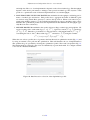
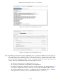
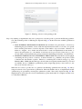
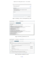
1
Infrastructure Configuration Service - user manual
version 0.2.0 - 11 December 2013
http://www.posecco.eu
Infrastructure Configuration Service - user manual
Contents
1
Introduction
2
2
Refinement process
3
3
Data models
5
3.1
Logical associations . . . . . . . . . . . . . . . . . . . . . . . . . . . . . . . . . . . . . . . .
5
3.2
Logical association implementations . . . . . . . . . . . . . . . . . . . . . . . . . . . . . . .
5
3.3
Abstract configurations . . . . . . . . . . . . . . . . . . . . . . . . . . . . . . . . . . . . . .
5
4
Use of the tool
7
4.1
Introduction . . . . . . . . . . . . . . . . . . . . . . . . . . . . . . . . . . . . . . . . . . . .
7
4.1.1
Automatic process . . . . . . . . . . . . . . . . . . . . . . . . . . . . . . . . . . . .
7
4.1.2
Manual process . . . . . . . . . . . . . . . . . . . . . . . . . . . . . . . . . . . . . .
7
4.2
Manual process - Data Protection . . . . . . . . . . . . . . . . . . . . . . . . . . . . . . . . .
8
4.3
Manual process - Filtering . . . . . . . . . . . . . . . . . . . . . . . . . . . . . . . . . . . .
15
1 / 19
Infrastructure Configuration Service - user manual
1
Introduction
This document provides an overview of the Infrastructure Configuration Service (ICS), which is the tool used
to transform the logical associations (LAs), generated by LA Generation Service, into abstract configurations
for Data Protection and Filtering in the PoSecCo workflow.
This service consists of a set of different modules with their own user interface. All of this modules and their
options are documented in the following sections.
For an introduction on the process see Sec. 2 and D3.6 “Models for generating the desired configurations” [?]
for a complete description.
The Sec. 3 provides a short description of data formats used, i.e., logical associations, logical association
implementations and abstract configurations.
The Sec. 4 is devoted to explaining how the tool works, documenting the refinement process to generate the
abstract configurations (from LAs), its internal modules and the graphical user interface.
2 / 19
Infrastructure Configuration Service - user manual
2
Refinement process
The Infrastructure Configuration Service (ICS) transforms logical associations (LAs) into abstract configurations. ICS is composed by the Data Protection and the Filtering modules that refine LAs into abstract configurations. The Data Protection is executed before the Filtering because the filtering rules depends on data
protection abstract configurations. For example, when IPsec is configured, the needed filtering rules must be
created to permit related traffic.
Both modules share the following workflow (depicted in Fig. 1):
• Read the LAs and Landscape. The first step retrieves the landscape description and the logical associations from the PoSecCo repository. Then, by using the landscape description, it generates an internal
(graph-based) model to represent the network, hosts, services and capabilities (e.g., filtering). The information needed to contact PoSecCo repository is gathered from a configuration.
• Generate all the LA implementations. Starting from the retrieved logical associations and internal
model (that contains the landscape information), this step generates the set of LA implementations. In
practice, according to the security mechanisms available in the landscape (i.e., ITResource having a Capability), the module identifies all the possible methods to enforce each logical association. In particular
for each filtering LA, the module identifies the different sets of firewalls (named LA filtering implementations) and the needed rules to satisfy the set of logical associations. For data protection policies,
the module explores the data protection technologies (e.g., IPsec, SSL/TLS, WS-Security, etc.) available into the landscape to satisfy the LAs. Similarly to filtering, the module generates the set of LA
implementations considering the available technologies and the network devices.
• Prune the LA implementations. Often, enforcing a security policy of a large network offers a huge
set of alternatives, LA implementations in PoSecCo terminology, that increase the complexity of the
optimization problem. In order to limit this complexity, LA implementations may be discarded either
according to some heuristics or by allowing users to explicitly discard some implementations. Therefore
this module can optionally perform pruning of generated LA implementations using a particular criterion.
For instance, a user may decide to discard certain implementations using devices with poor performance,
or avoid the concurrent use of specific devices for a given policy, or to force the use of a specific device. This step outputs the subset of LA implementations that will be actually used in the optimization
problem. This step is under development. Another interesting approach is the Inter Layer Analysis that
allows to discover the conflicts that exist in LA implementations. This is useful to identify when two implementations are identical, when an implementations shadows another one, when two implementations
can be substituted by a new one that includes the previous ones, etc..
• Optimization. This step is composed by two sub-modules that generate the mathematical optimization
problem and identify optimal solution (using an external solver). This step transforms the subset of LA
implementations into a mathematical optimization problem. The target function represents the objective
of the optimization (i.e., the goal function), typically a maximization or a minimization of a function. This
step also relies on other weights to express device performance, costs, security risks, and so on. Finally,
by using an external solver, the module extracts the optimal solution i.e., the LA implementations to use.
• Generate the abstract configurations. Once the tool has identified the optimal solution, this module
performs the following steps to generate the abstract configurations:
1. rule creation: the module adapts the information contained in each LA to derive the rules that need
to be inserted in each device according to its capabilities. For instance, for a firewall it identifies the
IP addresses, the protocol(s) and the port(s) and the fields to fill the rule conditions;
2. configuration generation: the module collects all the rules and completes the definition of the configuration adding other data, e.g, priorities, resolution strategies;
3. configuration commit: the tool write the abstract configurations into the PoSecCo repository.
3 / 19
Infrastructure Configuration Service - user manual
In the Data Protection module, this step also creates the logical associations (defining the reach privilege
and the technology used to ensure data protection) to permit traffic related to selected data protection LA
implementations.
Logical
Associations
Landscape
Read the LAs and Landscape
Generate all the LA implementations
...
LA1
implementations
LA2
implementations
LAn
implementations
Prune the LA implementations
Optimization
API
Generate the abstract configurations
conf1
conf2
conf3
... confn
Figure 1: Workflow
4 / 19
Solver
Infrastructure Configuration Service - user manual
3
3.1
Data models
Logical associations
A logical association, or LA for short, is an intermediate format between the policies and the configurations. It
is a lower-level directive than a policy, but it does not contains all the technical information of a configuration.
A logical association is an end-to-end prescription that is used to grant privileges to a subject over an object that
also adds the possibility to state additional constraints on subjects and objects and to add privilege properties.
The logical associations serve to define authorized communication channels and to state protection requirements
to data when they need to be communicated over the network.
In general a logical association contains the following data:
• the communication endpoints, that are a (single or multiple) source and a (single or multiple) destination.
Note that the LA endpoints are different from the policies endpoints. The policy endpoints are usually
IT services, users and so one, while the LA endpoints are low-level individuals which usually contains
IP addresses, ports and URIs;
• a privilege, that dictates the privilege between the two endpoints. For our case the privilege is always
LAReach that is the two endpoints can communicate;
• a set of security properties, used to select individual protections, e.g., confidentiality, data authenticity,
key exchange or peer authentication or aggregation of individual properties by means of templates (e.g.,
HighSecurityDataProtection). Additionally, a set of attributes are used to define other constraints on
the ISO/OSI layer where the protection has to be applied or the specific technology (e.g., SSL/TLS,
WS-Security, . . . ).
The complete description of Logical Association meta-model is presented in deliverable D3.6 “Models for
generating the desired configurations”.
3.2
Logical association implementations
An implementation of a logical association is a way to enforce a LA, formally defined as a set of associations
between a security control (taken from the landscape), and a set of configuration rules. In particular the Infrastructure Configuration Service manages two types of implementation: LA Filtering implementation and LA
Data Protection implementation. More precisely a filtering implementation identifies the set of filtering controls, available in the landscape, and a set of rules to enforce an LA. A data protection implementation identifies
the two endpoints, the technology (e.g., IPsec, TLS, etc.) and rules to enforce an LA. There exists at least an
implementation for a LA, the logical association is enforceable, otherwise it is non enforceable.
Every LA can be usually enforced by using more than one LA implementation. Each implementation is related
to the particular security capability of the devices it aims at configuring, in our case, there are filtering and
data protection implementations. When more than one implementation is provided for a logical association,
the pruning and optimization steps are performed to choose among them using a criteria (named target function). On the contrary, when a logical association is enforced only by one implementation, the pruning and
optimization are not required.
Within the Infrastructure Configuration Service, implementations are formally represented using the Logical
Association Implementation meta-model as described in deliverable D3.6 “Models for generating the desired
configurations”.
3.3
Abstract configurations
An abstract configuration specifies the set of security controls (technologies and properties, e.g., IKE parameters for IPsec), available in the landscape, to enforce the logical associations.
We distinguish the abstract configurations, that use vendor/product independent syntaxes and formats, from the
concrete configurations, configurations that can be directly deployed to a given security control. Configurations
5 / 19
Infrastructure Configuration Service - user manual
are expressed as sets of rules that depend on the control features and directly use the functionalities available
at the target control. In fact, even if they are independent of the actual control, also abstract configurations
need to be customized to capabilities: filtering controls configuration have peculiarities that are completely
different from the ones exposed by channel or message protection controls. Therefore, abstract configurations
are categorized by the security capability offered.
The Filtering Configuration contains a set of rules, defined using:
• packet filter conditions (e.g., source and destination IP address, source and destination port, protocol
type, etc.);
• application layer protocol conditions (e.g., HTTP, FTP, etc.);
• content filter conditions;
• stateful information;
• an action chosen among Allow, Deny, Reject;
• external data, e.g., a priority to express the rule position on the device;
• network interfaces where to enforce the rule.
In addition, a resolution strategy is applied to a Filtering Configuration.
The Data Protection Configuration contains a set of rules, defined using:
• packet filter conditions (e.g., source and destination IP address, source and destination port, protocol
type, etc.);
• two endpoints that enforce the rules
• an action to perform key exchange, authentication integrity and encryption;
• a set of properties used to configure technology dependent parameters for IPsec, SSL/TLS, IKE etc.;
• network interfaces where to enforce the rule.
Detailed information are described in deliverable D3.6 [?].
6 / 19
Infrastructure Configuration Service - user manual
4
Use of the tool
4.1
Introduction
The Infrastructure Configuration Service is composed by the Data Protection and the Filtering modules that
refine logical associations into abstract configurations. The Data Protection is executed before the Filtering
one because the filtering rules depends on data protection abstract configurations. For example, when IPsec is
configured, the related filtering rules must be created to permit its traffic. The tool automatically manages the
logical associations in the corresponding module.
The main GUI of the Infrastructure Configuration Service, depicted in Fig. 2, contains in the left part the
workflow steps and the right part is divided into Data Protection Explorer, Filtering Explorer and Optimization
Models tabs.
The Data Protection Explorer and Filtering Explorer contain the following information:
• the Logical associations view that contains the set of LAs loaded as input by the tool;
• the LA implementations view that contains the set of generated implementations (i.e., the set of security
controls and related technologies to enforce each LA) that satisfy the logical associations;
• the Abstract Configurations view that contains the set of abstract configurations (that enforce the LAs)
generated from the LA implementations according to an optimization goal.
The Optimization Models tab contains the Data Protection and Filtering optimization models represented using
the LP standard format.
The refinement can be automatic or it can be manually performed step by step whose steps are accessible in
Manual Process View.
4.1.1
Automatic process
The automatic process that can be executed by the user (by pressing the Generate All The Configurations
button), and selecting the optimization profiles (prompted to the user by means of a dialog window) for Data
Protection and Filtering before starting the process.
4.1.2
Manual process
The following section describes the manual process discussing the steps and related views. Similarly, the
automatic process performs the same steps and provides the same information.
7 / 19
Infrastructure Configuration Service - user manual
Figure 2: IC Area main window
4.2
Manual process - Data Protection
To present the specific views and the information related to refinement of the logical associations, we start from
the Data Protection LAs using the manual process depicted in Fig. 3.
8 / 19
Infrastructure Configuration Service - user manual
Figure 3: Data Protection: Manual process menu
Step 1. By clicking on Read the LAs and the landscape the tool loads the Data Protection logical associations and
the landscape. The landscape is loaded from MoVE repository and the set of logical associations from
an internal data model and generated by LA Generation Service. This modules loads only the set of LAs
that requires Confidentiality. The input set of LAs is displayed in Fig. 4. Considering the related view,
for each LA we have the subject, the object, the LAReach privilege and the template (Confidentiality).
In this phase the other menu items are disabled;
Figure 4: Data Protection: LAs details
Step 2. By clicking on Generate all the LA implementations the tool generate all the possible Data Protection
implementations. The resulting set of LA implementations is displayed in Fig. 5. Considering the related
view, each LA implementation shows two endpoints to enforce the LA, the selected technology (e.g.,
9 / 19
Infrastructure Configuration Service - user manual
IPsec, SSL/TLS, etc.) and the related mode (e.g., end-to-end, site-to-site, remote-access). You can see
also cases where the LA is not implementable;
Figure 5: Data Protection: LA implementations details
Step 3. By clicking on Prune the LA implementations the tool prunes the logical associations, i.e., it discards a
subset of them using a heuristic selected by the user. The tool proposes two pruning approaches (Fig. 6):
Classical pruning and inter-layer analysis.
Figure 6: Data Protection: selection of the pruning mode
The Classical pruning Fig. 7 defines a set of filters organised as general and specific. A general filter is
applied on the complete set of the logical associations, otherwise a specific filter is applied only on a LA,
selected by the user. The available filters, both for specific and general, are:
– select the LAImpls with cost less than a specific value (defined by the user);
– select the LAImpls with security risk less than a specific value (defined by the user);
– select the LAImpls with performance greater than a specific value (defined by the user);
– select the LAImpls with a particular technology and related properties (defined by the user, for
example IPsec in site-to-site mode).
10 / 19
Infrastructure Configuration Service - user manual
Figure 7: Data Protection: selection of the pruning profile
The Inter Layer Analysis allows to discover the conflicts that exist in LA implementations (LAImpl).
These conflicts were defines as Inter Layer Conflicts and they could be considered not critical errors but
warnings.
In particular we have classified five types of conflicts that are:
Equivalence, when two LAImpls are identical;
Inclusion, when a LAImpl shadows another one, hence the first LAImpl is included by the second;
Correlation, when two LAImpls can be substituted by a new LAImpl that includes the previous ones;
Affinity, when there are two identical LAImpls but for the mode (namely one site-to-site and one endto-end);
Irrelevant, when a LAImpl can be safely removed without changing the semantic of the network.
The Inter Layer Conflicts are described using a multi-graph, where each sub-graph represents a network
node. To be more specific, a sub-graph is composed by a set of vertices layered on four levels, which are:
– The untruthful communications;
– The trustful communications at IP level (like IPSec);
– The trustful communications at transport level (e.g., SSL/TSL);
– The trustful communications at application level (like SSH or WS-Security).
The main wizard of the Inter Layer Analysis, shown in Figure 8, is organized in two main parts. At the
top, there is the list of the conflicting LAImpls, while below there is the multi-graph, which represents
the conflicts between one or two LAimpls, belonging to the previous list. Note that the first column of
the list shows also the conflict type.
11 / 19
Infrastructure Configuration Service - user manual
Figure 8: Inter-Layer Analysis: conflict visualization
When the user selects the conflicting LAImpl(s), it is possible to resolve the conflict using the button “Resolve conflict...”. After this, a new resolution window will be opened (as we can see in Figure 9). In this
new window, the administrator can choose the specific actions that will be executed on that LAImpl(s).
In particular, the possible actions that can be applied per conflict are:
Delete: delete the specified LAImpl;
Force: force the use of this LAImpl to implement a logical association;
Unconstrained: leave the optimizer wheather the specified LAImpl must be discarded or used, according to the selected optimization function;
Create unconstrained: create a new LAImpl that shadows the previous LAImpls — the optimizer can
choose to discard this newly created LAImpl;
Create forced: create a new LAImpl that shadows the previous LAImpls — this LAImpl will be forced
in the optimal solution.
Please note that the GUI will usually not allow the user to choose between all the previously listed actions
in order to avoid an unwanted deletion of semantics. For instance during an inclusion resolution it is not
possible to delete the including LAImpl, since this action can negatively affect the final configurations.
Figure 9: Data Protection: resolve conflict
Step 4. By clicking on Optimization the user is prompted to select the profile to perform the Data Protection
optimization. The available profiles for Data Protection are depicted in Fig. 10. In this release the
available optimization profiles are:
1. MIN IMPLEMENTATION COST AND MAX THROUGHPUT PROFILE that minimizes the cost
of an implementation and maximizes the throughput according to a set of weights (cost, performance) that are provided independently to the tool and associated to landscape for technologies
12 / 19
Infrastructure Configuration Service - user manual
and endpoints. The cost of an implementation depends on the selected technology. The throughput
depends on the device performance to manage a data protection technology. The objective of this
profile is to optimize the trade-off between implementation costs and throughput;
2. MAX THROUGHPUT WITH VPN PROFILE that maximizes the throughput considering performance of technologies and devices. This profile tries to aggregate the traffic of different logical
associations using shared IPsec gateways to enforce data protection. When a LA cannot be protected using an IPsec gateway, e.g., the available implementations support only IPsec end-to-end or
SSL/TLS, the optimization profile selects the implementation that maximize the throughput (typically IPsec in end-to-end mode);
3. MIN RISK PROFILE that minimizes the security risk according to technologies and endpoints. We
assign a security risk to each technology (tjr , e.g., tipsec
), logical association (lrk e.g., lr1 ) and device
r
m
1
2
1,1
(dr e.g., dr , dr ). Then the tool calculates a composite risk for a LA implementation (in,p
r e.g., ir
1
ipsec
1
2
considering the risk of: LA lr , IPsec technology tr
and devices dr , dr ) using the formula:
1 2
ipsec · l1 )).
i1,1
r = dmax(max(dr , dr ), log2 (tr
r
When the user selects a profile, the tool generates the Data Protection optimization model (Fig. 11) and
by using an external solver performs the optimization. This task identifies the set of implementations
that optimize the goal, specified by selecting the optimization profile. The result is depicted in Fig. 12.
The implementations selected by the solver are identified by a green check mark. To configure external
solver see the “Installation Manual”;
Figure 10: Data Protection: selection of the Optimization profile
13 / 19
Infrastructure Configuration Service - user manual
Figure 11: Data Protection: Optimization model
Figure 12: Data Protection: Optimization results
Step 5. By clicking on Generate the abstract configurations the tool generates the Data Protection abstract configurations. The results are displayed in Fig. 13. This step also creates the logical associations (defining
the reach privilege and the technology used to ensure data protection) to permit traffic related to data
protection abstract configurations. These LAs are stored in the internal data model represented as an
ontology. The view is implemented using a tree and organized as follow:
– the first level contains the set of configured devices (e.g., s1);
– the second level contains the set of Data Protection Configurations;
– the third level defines the configuration properties and the related rules. For example the Fig. 13
shows that we configure IPsec (end-to-end mode) on s1.os using a First Matching Rule strategy.
– the fourth level defines the properties of a configuration rule. For example the Fig. 13 shows the
related packet filter conditions (source and destination IP address, direction, etc.).
14 / 19
Infrastructure Configuration Service - user manual
Figure 13: Data Protection: Abstract configurations
4.3
Manual process - Filtering
The refinement of Filtering logical associations follows the same process as the Data Protection. Therefore,
similarly to previous case, we present the views of Filtering module using the manual process depicted in
Fig. 14.
Figure 14: Filtering: Manual process menu
Step 1. By clicking on Read the LAs and the landscape the tool loads the Filtering logical associations and the
landscape. The landscape and the set of logical associations are loaded from MoVE repository. The
input set of LAs is displayed in Fig. 15. In this phase the tool also loads the LAs generated by Data
Protection module. According to the related view, for each LA we have the subject, the object, the
LAReach privilege and the confidentiality template (Confidentiality). In this phase the other menu
items are disabled;
15 / 19
Infrastructure Configuration Service - user manual
Figure 15: Filtering: LAs details
Step 2. By clicking on Generate all the LA implementations the tool generates all the possible Filtering implementations. The resulting set of LA implementations is displayed in Fig. 16. According to the related
view, each LA implementation has at least a path that may contain a set of filtering devices. You can see
also cases where the LA is not implementable (e.g., the first LA in Fig. 16 IT ITP SPSAdmins ccD . . . );
Figure 16: Filtering: LA implementations details
Step 3. By clicking on Prune the LA implementations the tool prunes the logical associations, i.e., it discards a
subset of them using a heuristic selected by the user.
Similarly to Data Protection, the Filtering pruning Fig. 7 defines a set of filters organised as general and
specific. A general filter is applied on the complete set of the logical associations, otherwise a specific
filter is applied only on a LA, selected by the user. The available filters, both for specific and general,
are:
– select the LAImpls with cost less than a specific value (defined by the user);
– select the LAImpls with security risk less than a specific value (defined by the user);
– select the LAImpls with performance greater than a specific value (defined by the user).
16 / 19
Infrastructure Configuration Service - user manual
Figure 17: Filtering: selection of the pruning profile
Step 4. By clicking on Optimization the user is prompted to select the profile to perform the Filtering optimization. The available profiles for Filtering are depicted in Fig. 18. In this release the available optimization
profile is:
1. MAX FILTERING PERFORMANCE PROFILE that maximizes the performance of devices by
minimizing the global number of rules. Each LA implementation installs a set of rules on a specific
device and the performance of a device depends on the number of processed rules. Therefore we
define two weights: one to define the inserted rule for each LA implementation and another to
express the performance (i.e., the number of rules that can be processed in a time unit, e.g., in 1
second). This profile maximizes the global performance minimizing the number of installed rules;
2. FILTERING SORTING RULES CONSIDERING THROUGHPUT that maximizes the throughput
considering the rule positions on devices. Software firewalls (e.g., Netfilter) adopt linear search
to find the rule that matches a packet. Therefore, considering the resolution strategy (e.g., First
Matching Rule - FMR) and the traffic type, the rules that are frequently matched must be positioned
accordingly. In case of FMR, the optimization profile assigns high priority to these rules (i.e., the
rules are positioned at the top);
When the user selects a profile, the tool generates the Filtering optimization model (Fig. 19) and by
using an external solver it performs the optimization. This task identifies the set of implementations that
optimize the goal, specified by selecting the optimization profile. The result is depicted in Fig. 20. The
implementations selected by the solver are identified by a green check mark. To configure external solver
see “Installation Manual”;
17 / 19
Infrastructure Configuration Service - user manual
Figure 18: Filtering: selection of the Optimization profile
Figure 19: Filtering: Optimization model
Figure 20: Filtering: Optimization results
18 / 19
Infrastructure Configuration Service - user manual
Step 5. By clicking on Generate the abstract configurations the tool generates the Filtering abstract configurations. The results are displayed in Fig. 21. The view is implemented using a tree and organized as
follow:
– the first level contains the set of configured devices (e.g., fw1);
– the second level contains the set of Filtering Configurations (typically one for each firewall);
– the third level defines the configuration properties and the related rules. For example the Fig. 21
shows that we configure filtering capability on fw1.os using a First Matching Rule strategy and a
Deny All as default action.
– the fourth level defines the properties of a configuration rule. For example the Fig. 21 shows: the
priority (the position of a rule into the firewall), the stateful information, the action (allow, deny,
reject), the input and output interfaces and the related packet filter conditions (source and destination
IP address, direction, etc.).
Figure 21: Filtering: Abstract configurations
19 / 19