1
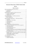
GREENTEL Serial Device Server
User Manual
For SE1001 1 Port RS232/RS422/RS485
SE1002 2 Ports RS232/RS422/RS485
-1-
ANNOUNCEMENTS ......................................................................................................................... 4 1. SE100X INTRODUCTION ...................................................................................................... 6 1.1 SPECIFICATIONS: ........................................................................................................................ 6 1.2 PRODUCT KIT: ............................................................................................................................. 7 2. HARDWARE INTRODUCTION ............................................................................................. 8 2.1.1 SE1001 ................................................................................................................................... 8 2.1.2 SERIAL PORT (SOFTWARE SELECTABLE RS232/RS422/RS485) .................................... 8 2.1.3 POWER SUPPLY ........................................................................................................................ 9 2.1.4 LED INDICATOR ....................................................................................................................... 9 2.2.1 SE1002 ................................................................................................................................. 10 2.2.2 SERIAL PORT (PLEASE REFER TO ORDERING INFORMATION) ............................................. 10 2.2.3 POWER SUPPLY ...................................................................................................................... 12 2.2.4 LED INDICATOR ..................................................................................................................... 12 3. APPLICATION INTRODUCTION ...................................................................................... 13 4. WEB CONSOLE CONFIGURATION .................................................................................. 16 4.1 PC CONFIGURATION .................................................................................................................. 16 4.2 LOGIN ......................................................................................................................................... 16 4.3 SERVER MENU->SERVER INFORMATION ................................................................................. 17 4.4 SERIAL PORT COMMUNICATION SETTINGS->PORT1 ............................................................. 18 4.5 MODE->PORT1 ......................................................................................................................... 20 4.6 ROUTE TABLE ............................................................................................................................. 37 4.7 HOST TABLE ............................................................................................................................... 38 4.8.1 AUTHORITY MANAGEMENT->SECURE SETTING .................................................................. 38 4.8.2 AUTHORITY MANAGEMENT->IP ADDRESS ACCESS ........................................................... 39 4.8.3 AUTHORITY MANAGEMENT->MAC ADDRESS ACCESS ....................................................... 39 4.9 USERS......................................................................................................................................... 39 4.10.1 SYSTEM STATS->SYSTEM INFORMATION ......................................................................... 40 4.10.2 SYSTEM STATS->NETWORK INTERFACE INFORMATION .................................................. 40 4.10.3 SYSTEM STATS->ACTIVE ROUTING INFORMATION.......................................................... 40 4.10.4 SYSTEM STATS->SERIAL PORT COMMUNICATION INFORMATION .................................. 40 4.10.5 SYSTEM STATS->ARP ADDRESS MAP INFORMATION ..................................................... 40 4.10.6 SYSTEM STATS->TCP SOCKET INFORMATION................................................................. 41 4.10.7 SYSTEM STATS->ACTIVE TCP SOCKET INFORMATION ................................................... 41 4.10.8 SYSTEM STATS->UDP INFORMATION .............................................................................. 41 4.11 RESET PORTS .......................................................................................................................... 41 4.12 SAVE CONFIGURATIONS ......................................................................................................... 41 4.13 LOAD FACTORY SETTINGS ...................................................................................................... 41 -2-
4.14 REBOOT SERVER ..................................................................................................................... 41 5. TELNET CONFIGURATION.................................................................................................. 42 6. HOW TO RESET TO FACTORY DEFAULTS SETTINGS........................................... 43 6.1 RESET BY WEB CONSOLE ......................................................................................................... 43 6.2 RESET BY TELNET ...................................................................................................................... 43 7. FIRMWARE UPGRADE UTILITY....................................................................................... 44 8. SUPPORT ..................................................................................................................................... 47 -3-
Announcements
Thank you for choosing our product. GREENTEL SE100x provides high performance
serial to Ethernet connectivity, allows 8 simultaneously access to one port.
GREENTEL SE100x supports TCP server, TCP client, UDP, TCP Virtual Port, Multi
screens TTY, PPP dialout/daemon, Line printer daemon mode.
GREENTEL SE100x has RS232, RS422 or RS485 (2 and 4 wire support).
Applications such as POS, Access Control and Any Serial Port Connectivity.
Please read this manual carefully before using the product.
Copyright Announcement
Copyright GREENTEL LIMITED 2010.
All rights reserved.
Reproduction, transfer, distribution or storage of part or all of the contents in this
document in any form without the prior written permission of GREENTEL is
prohibited.
Information Edition: GL – A – SE100x – 1.3
-4-
WEEE Notice
The Directive on Waste Electrical and Electronic Equipment (WEEE), which entered
into force as European law on 13th February 2003, resulted in a major change in the
treatment of electrical equipment at end-of-life.
The purpose of this Directive is, as a first priority, the prevention of WEEE, and in
addition, to promote the reuse, recycling and other forms of recovery of such wastes
so as to reduce disposal.
The WEEE logo (shown at the left) on the product or on its box indicates that this
product must not be disposed of or dumped with your other household waste. You
are liable to dispose of all your electronic or electrical waste equipment by relocating
over to the specified collection point for recycling of such hazardous waste. Isolated
collection and proper recovery of your electronic and electrical waste equipment at
the time of disposal will allow us to help conserving natural resources. Moreover,
proper recycling of the electronic and electrical waste equipment will ensure safety
of human health and environment. For more information about electronic and
electrical waste equipment disposal, recovery, and collection points, please contact
your local city centre, household waste disposal service, shop from where you
purchased the equipment, or manufacturer of the equipment.
-5-
1. SE100x Introduction
GREENTEL SE100x provides high performance serial to Ethernet connectivity,
allows 8 simultaneously access to one port.
GREENTEL SE100x supports TCP server, TCP client, UDP, TCP Virtual Port, Multi
screens TTY, PPP dialout/daemon, Line printer daemon mode.
GREENTEL SE100x has RS232, RS422 or RS485 (2 and 4 wire support).
Applications such as POS, Access Control and Any Serial Port Connectivity.
1.1 Specifications:
Processor
CPU
32 bit 100MHz
FLASH
8 MB
Serial
(SE1001)
Number
(SE1001)
Serial Interface
Serial
Communication
Parameters
Serial Signals
Software
LED Indicators
of
Ports
Software selectable RS-232/422/485
1
Connectors for External
(SE1001)
DB9 male
Serial
(SE1002)
RS-232/422/485
Number
(SE1002)
LAN Interface
Standards
Standards
of
Ports
2
Connectors for External
(SE1002)
RJ45
Serial Line Protection
15 KV ESD protection for all signals
Number of Ports
1
Speed
10/100 Mbps
Connectors for External
8-pin RJ45
Magnetic Isolation
1.5 KV built-in protection
Data Bits
5, 6, 7, 8
Stop Bits
1, 1.5, 2
Parity
None, Even, Odd, Space, Mark
Flow Control
RTS/CTS and XON/XOFF
Baud rate
50 bps to 230.4 Kbps
RS-232
TxD, RxD, RTS, CTS, DTR, DSR, DCD, GND
RS-422
Tx+, Tx-, Rx+, Rx-, GND
RS-485-4w
Tx+, Tx-, Rx+, Rx-, GND
RS-485-2w
Data+, Data-, GND
Network Protocols
HTTP, Telnet, ICMP, IP, TCP, UDP, DHCP
Driver Support
Windows TCP Virtual Port driver, Fixed TTY driver (for SCO Unix, Linux)
Configuration Options
Web Console, Serial Console, Telnet Console
LED
(SE1001)
Indicators
Power, Link, 10/100M
LED
(SE1001)
Indicators
100M, Link, Power, Port1, Port2
Reset Button
Reset Button
Restore to factory default by hardware
Physical
Characteristics
Enclosure
1mm Aluminum with integrated wall mounts
Weight (SE1001)
300 g
-6-
Environmental
Limits
Power Supply
Approvals
Warranty
z
z
z
z
Dimensions (SE1001)
Without ears (L x W x H): 75 x 55 x 23 mm
With ears (L x W x H): 75 x 82 x 23 mm
Weight (SE1002)
400 g
Dimensions (SE1002)
Without ears (L x W x H): 113 x 77 x 23 mm
With ears (L x W x H): 113 x 103 x 23 mm
Operating Temperature
0 to 55°C
Operating Humidity
5 to 95% RH
Input Voltage
5VDC
Interface
5mm pluggable terminal block
Safety
EN60950-1
EMC
CE (EN55022 Class A, EN55024), FCC Part 15 Subpart B Class A
Warranty Period
5 years (accessories has 1 year warranty)
1.2 Product Kit:
Serial Device Server (1 serial port)
AC/DC Adapter optional
35mm Din-rail mounting kit optional
CD
-7-
2. Hardware Introduction
2.1.1 SE1001
Figure 2.1 Hardware Introduction
2.1.2 Serial Port (software selectable RS232/RS422/RS485)
Before installation, please prepare serial cable according to follow pin
assignment.
Pin Assignment: DB9 male connector
PIN RS232 RS422 RS485-4w RS422-2w
1
DCD
RTS2
RXD
DATA- TXDTXD3
TXD
DATA+ TXD+
TXD+
4
DTR
RXD+
RXD+
5
GND
GND
GND
GND
6
DSR
RXDRXD7
RTS
RTS+
-8-
8
9
CTS
CTS+
CTS-
Figure 2.2 Serial Port
2.1.3 Power Supply
Figure 2.3 Power Supply
Notice: Please connect 5VDC power supply with SE1001 power supply terminal
block.
Please take care about the polarity, do not make reverse connection.
2.1.4 LED indicator
LED
PWR
Indicator
Description
Power supply
indicator (Red)
Off
Power off
On
Power on
Blinking
N/A
LINK
10/100M
Running status indicator
(Green)
Ethernet cable is
disconnected, or has a
short
The device is connected to
a Ethernet connection
Data is transmitting on
Ethernet
Ethernet Rate
(Yellow)
10M
-9-
100M
N/A
2.2.1 SE1002
Figure 2.4 Hardware Introduction
2.2.2 Serial Port (Please refer to ordering information)
Before installation, please prepare serial cable according to follow pin
assignment.
RJ45
PIN
1
2
3
4
5
6
7
8
serial connector
RS232 RS485-2w
TXD
DATA+
RXD
DATARTS
CTS
DSR
GND
GND
DTR
DCD
RS485-4w
TXD+
TXDRXD+
RXD-
RS422
TXD+
TXDRXD+
RXD-
GND
GND -
- 10 -
RJ45
RJ45
PIN
1
2
3
4
5
6
7
8
RS232 to DB9/DB25 connector
DB9 Male DB9 Female
RJ45 PIN DB9 PIN DB9
TXD 3
TXD 2
TXD
RXD 2
RXD 3
RXD
RTS 7
RTS 8
RTS
CTS 8
CTS 7
CTS
DSR 6
DSR 4
DSR
GND 5
GND 5
GND
DTR 4
DTR 6
DTR
DCD 1
DCD
DB25 Male
PIN DB25
2
TXD
3
RXD
4
RTS
5
CTS
6
DSR
7
GND
20
DTR
8
DCD
DB25
PIN
3
2
5
4
20
7
6
Female
DB25
TXD
RXD
RTS
CTS
DSR
GND
DTR
Figure 2.5 Serial Port (RJ45 connector)
Figure 2.6 DB9 Male Connector
Figure 2.7 DB25 Male Connector
- 11 -
2.2.3 Power Supply
Notice: Please connect 5VDC power supply with SE1002 power supply terminal
block.
Please take care about the polarity, do not make reverse connection.
2.2.4 LED indicator
LED
PWR
LINK
Indicator
Description Power
Running
supply
status
indicator indicator
(Red)
(Green)
Off
Power
Ethernet
off
cable is
disconnected,
or has a short
On
Power
The device is
on
connected to
a Ethernet
connection
Blinking
N/A
Data is
transmitting
on Ethernet
10/100M
Port1
Port2
Ethernet
Rate
(Yellow)
Serial Port 1
(Green)
Serial Port 2
(Red)
10M
No data
No data
100M
Data
transmission
Data
transmission
N/A
N/A
N/A
- 12 -
3. Application Introduction
SE1001 works as TCP Server:
1. SE1001 connects to PLC via serial port
2. SE1001 can be configured as TCP server, has fixed IP address
3. PC can be configured as TCP client
4. TCP client in PC requests a connection from the TCP server SE1001, then PC
to establish a connection with SE1001.
5. Once the connection is established between SE1001 and PC, data can be
transmitted bi-directional.
6. TCP Server mode supports up to 6 simultaneous connections, so that multiple
hosts can collect data from the same serial device at the same time.
Figure 3.1: SE1001 works as TCP Server
SE1001 works as TCP Client:
1. SE1001 connects to POS via serial port
2. SE1001 can be configured as TCP client
3. Server can be configured as TCP server, , has fixed IP address
4. TCP client in SE1001 requests a connection from the TCP server, then SE1001
to establish a connection with the TCP server.
5. Once the connection is established between SE1001 and PC, data can be
transmitted bi-directional.
- 13 -
Figure 3.2: SE1001 works as TCP Client
SE1001 works as UDP mode
1. SE1001 connects to LED Displays via serial port
2. SE1001 can be configured as UDP mode
3. Compare to TCP communication, UDP is faster and more efficient, also none
guaranteed (no connection requested)
4. In UDP mode, user can unicast or multicast data from Control Room to one or
more LED Displays, vice verse is also true
Figure 3.3: SE1001 works under UDP mode
SE1001 works under Tunneling
In the case of the serial connection is established with two or more SE1001 to
- 14 -
send data over TCP/IP Network .It can avoid RS-232 interface 15 meter
distance limitation imposed.
Figure 3.4: SE1001 works under tunneling mode
SE1001 works under TCP Virtual Port mode
The SE1001 comes equipped with COM drivers that work with Windows
NT/2000/XP systems, and also TTY drivers for Linux systems. The driver
establishes a transparent connection between host and serial device by
mapping the IP: Port of the SE1001’s serial port to a local COM/TTY port on the
host computer. Virtual Port Mode also supports up to 6 simultaneous
connections, so that multiple hosts can collect data from the same serial device
at the same time.
Figure 3.4: SE1001 works under TCP Virtual Port mode
- 15 -
4. Web Console Configuration
4.1 PC Configuration
SE1001 has default IP 192.16.0.233. Please configure your Ethernet connection
as follow, then PC connects to SE1001 should set to IP address 192.168.0.x
(cannot be 192.168.0.233):
4.2 Login
SE1001 has user friendly Web Console.
Open Internet Explorer (or other web browsers), enter the IP address of SE1001
in the URL link field, e.g. http://192.168.0.233 (- default IP of SE1001).
After that, user will see follow page.
Notice: There is no login interface default, unless after user set password in the
web console.
- 16 -
4.3 Server Menu->Server Information
Figure: SE1001
Figure: SE1002
Server Menu->Server Information
Item
Description
Server Name
Input the server name
Server Position
Input the sever installation position
Ethernet
IP
Ethernet port IP address
Address
Select the Ethernet mode from “auto, 100f,
Ethernet Mode
100h, 10f, 10h”
- 17 -
Default Value
192.168.0.233
Auto
DHCP Enabled
DHCP Client ID
Default
Gateway
Primate
DNS
Server
Second
DNS
Server
Console
Timeout
Advanced
Settings
auto-10/100M auto-negotiation
100f-100M full mode
100h-100M half mode
10f-10M full mode
10h-10M half mode
Enable DHCP client or disable DHCP client
Input DHCP client ID
No
Default Gateway for Ethernet port
Primate DNS Server address for Ethernet
port
Second DNS Server address for Ethernet
port
Set the length of login timeout
5 minutes
Boot Host and Boot File
4.4 Serial Port Communication Settings->Port1
Serial Port Communication Settings->Port1
Item
Description
Baudrate
Data Bits
Parity
Stop Bits
Flow Control
Select from “300 bps to 460.8 kbps”
Select from “5, 6, 7, 8”
Select from “n, o, e, s, m”
Select from “1, 2”
Select from “none, xon/xoff, rts/cts”
Select
from
“RS232,
RS422,
RS485_Full”
RS485_Half-RS485 half mode
RS485_Full-RS485 full mode
Type
of
Connection
Default
Value
9600 bps
8
None
1
None
RS485_Half,
Advanced
Settings
Set if necessary
FIFO
Select from “yes, no”.
First in and first out, take effect when baud rate is
large than 19200, FIFO=16 bytes
- 18 -
RS232
yes
Lock
tXON
tXOFF
TX Empty
Del String
RX Freetime
RX
Length
TX
Time
XANY
Max
Block
Available when working under TCP Virtual Port or
TCP/UDP Socket’s Telnet mode. SE1001 receives
remote command for changing serial port settings
from host.
Select from “no, yes”.
no-run the command
yes-do not run the command
Transparent XON, select from “no, yes”
no-do not upload XON to network
yes-upload XON to network
Transparent XOFF, select from “no, yes”
no-do not upload XOFF to network
yes-upload XOFF to network
SE1001 transmit data from Ethernet to serial port,
software read data from Ethernet port when there is
x byte in serial port Tx buffer.
x is 16 as default.
SE1001 receive data from serial port, which matches
with Del Strings, then SE1001 will package data
received before matching together with data
matched with Del Strings as one TCP or UDP
package.
When input 1-6 Hex code, 00 stands for common.
Default is to leave it as blank, SE1001 will not match
Del String.
When SE1001 receive data from serial port, should
wait for the next byte.
If the next byte is not coming in RX Freetime,
SE1001 will package current data as one TCP or UDP
package.
The range is 1-5000 ms.
SE1001 will process as default if do not set this item.
Different baudrate has different default settings.
When baudrate as 9600, Freetime is the time
transmit 4 bytes.
When baudrate is more large than 9600, Freetime is
the time transmit 32 bytes.
Freetime = 4x (10/baudrate) seconds
When SE1001 receive data from serial port meet
maximum byte number, and then SE1001 will
package the data as one TCP or UDP package.
The range is 1-4096.
SE1001 will process as default if do not set this item.
Rx Length = max (baudrate/10, 1024)
When SE1001 stop transmit data, serial port buffer
will be cleaned after TX Block Time.
It is available when enable serial port flow control.
The range is 0-30000 seconds.
0 stands for do not clean the data.
Transmit or stop transmit when serial port works at
stop bits.
It is only available when follow control set as
- 19 -
no
no
no
16
120
no
DTR ON
Keepalive
Baud Adjust
Note
“Xon/Xoff”.
yes-transmit any data from serial port
no-only transmit data after receiving XON.
Select from “no, yes”.
no-DTR is off
yes-DTR is on
Auto detects data availability in serial port in
Keepalive time.
If there is no data in serial port for Keepalive time,
then reset the serial port.
Adjust baudrate when it is less than 19200.
-1-decrease 5%
0-do not change it
1-increase 5%
Only 1 item is available from “RX Freetime, RX Max
Length, TX Block Time”.
There would be error when calculating RX Freetime,
RX Max Length.
no
120
0
4.5 Mode->Port1
Mode->Port1
Item
Communication
Mode
Sessions
Authentication
Default
Value
Description
Select from “TCP Virtual Port, UDP Virtual Port,
TCP/UDP socket, Multi screens TTY, PPP dialout,
PPP daemon, Line printer daemon, MCP, Simple
UDP”
TCP simultaneous connections, select from “1 to
6”
Select from “none, local”
TCP
Virtual
Port
1
None
TCP Virtualport
Please install “Real Port” software before using TCP and UDP Realport.
- 20 -
- 21 -
UDP Realport
TCP/UDP Socket
- 22 -
Mode->Port1->TCP/UDP Socket
Item
Description
Default
Value
TCP Data Mode
Select from “raw, telnet”
raw-serial
port
data
transparent
transmission
telnet-serial port data transmitted under
Telnet/RF2217 format
raw
Local Port (available in
TCP server mode, UDP
mode)
TCP server port which allows remote TCP
client connection
10001
CR As
LF As
Sessions
Strip NULL
Authentication
Select from “none, cr, lf, cr-lf”
none-when receiving “Enter” from serial
port, do not send to Ethernet port
cr- when receiving “Enter” from serial
port, send to Ethernet port
lf- when receiving “Enter” from serial port,
send “Line Feed” to Ethernet port
cr-lf-when receiving “Enter” from serial
port, send “Enter” and “Line Feed” to
Ethernet port
Select from “none, cr, lf, cr-lf”
none-when receiving “Line Feed” from
serial port, do not send to Ethernet port
cr- when receiving “Line Feed” from serial
port, send to Ethernet port
lf- when receiving “Line Feed” from serial
port, send “Enter” to Ethernet port
cr-lf-when receiving “Line Feed” from
serial port, send “Enter” and “Line Feed” to
Ethernet port
TCP simultaneous connections, select from
“1 to 6”
Select from “none, local”
- 23 -
cr
lf
1
None
(available
in
server mode)
TCP
Auth Prompt (available
in TCP server mode)
none-no authentication when TCP client
start connecting to TCP server
local-require authentication when TCP
client start connection to TCP server, user
should also set authentication information
in “Users” page
Select from “no, yes”
no-no login popup when TCP client
connecting to TCP server
yes-has login popup including user and
password when TCP client connecting to
TCP server
SERVER First
Protocol
Peer Host (available in
TCP client mode, UDP
mode)
Peer Port (available in
TCP client mode, UDP
mode)
Connect (available in
TCP client mode)
Disconnect (available
in TCP client mode)
Freetime (available in
TCP client mode)
Select from “TCP client, TCP server, UDP”
TCP client-SE1001 works under TCP client
mode, requests connection from TCP
server
TCP server-SE1001 works under TCP
server mode, waiting for TCP client
connection
UDP-SE1001 works under UDP mode,
works as both client and server
Remote host IP address
Remote host port
Select from “always, char, dcdon, dsron”
always-start TCP connection to remote
host after power on
char-start TCP connection to remote host
when receiving data from serial port
dcdon-start TCP connection to remote host
when DCD signal level is high
dsron-start TCP connection to remote host
when DSR signal level is high
Select from “none, dcdoff, dsroff, break”
none-do not stop TCP connection to
remote host any time
dcdoff-stop TCP connection to remote host
when DCD signal level coming from high to
low
dsroff- stop TCP connection to remote host
when DSR signal level coming from high to
low
break-stop TCP connection to remote host
when receiving “break”
Set from “0 to 10000 seconds”
Auto disconnect in Freetime when there is
no data transmission
- 24 -
always
none
Multi Screens TTY
Mode->Port1->Multi Screens TTY
Item
Description
Screens
Term Type
Supported screen number, select from “1 to 6”
Terminal emulation type
Select from “cr, auto”
cr-after terminal input “Enter”, then SE1001 connects
to host
auto-terminal auto connects to host after power on
Extra log off way besides standard log off, select from
“none, dcdoff, dsroff, break”
none-no extra log off way
dcdoff-log off when DCD signal level coming from high
to low
dsroff-log off when DSR signal level coming from high
to low
break-log off when pressing Ctrl+Break
Display connection status on terminal when SE1001
connecting to Unix, select from “yes, no”
yes-display
no-do not display
Auto
Connect
Logoff
Prompt
- 25 -
Default
Value
1
Vt100
cr
none
yes
Modem
Mode
Dynamic
Dial
Modem Init
Command
Modem Dial
Command
Phone
Number1
Phone
Number2
Phone
Number3
Phone
Number4
Callback
Callback
Phone
Mode
After connecting modem to SE1001 serial port,
Terminal could remote dial in, dial out and call back.
Select from “none, in, out”
none-modem control unavailable
in-modem is waiting for dial in
out-modem dials out using phone number
Select from “no, yes”
no-when modem works under dial out mode, it only
dials out using Phone Number1
yes-when modem works under dial out mode, it first
dial out using Phone Number1, if failed, then try Phone
Number2, Phone Number3, Phone Number4 until
successful
Initial command for dial in and dial out.
Usually it is “ats0=1&c1&d2” for dial in and
“ats0=0&c1&d2” for dial out
Dial out Phone Number1
Dial out Phone Number2
Dial out Phone Number3
Dial out Phone Number4
Working mode for connecting to terminal, select from
“telnet, rtelnet”
telnet-no need driver for Unix, available for any Unix
supports TCP/IP. After input “Username” and
“Password”, it supports auto log in host. Should also
input host item
rtelnet-require driver for Unix. Fixed_TTL is available
when log in Unix. Host, Username, Password are
unavailable in this mode
Currently supports drivers for SCO Unix and Linux
Host
Switch
Code
Available when “Screens” is more than 1. There are 2
ways to save screen history information, save in
Terminal or save in SE1001. Save in Terminal is
available when terminal supports this function, and
provide command to switch screen. Save in SE1001 is
available no matter terminal supports save in terminal
function or not.
User could switch screen by pressing hot key on
terminal, it could be ASCII or Hex.
Select from “terminal, server”
terminal-save in terminal
server-save in SE1001
- 26 -
None
no
Available when work under “terminal” mode.
SE1001 provides some famous manufacturer’s code,
user can select after pressing “Ctrl+L”, including
Newstar, Greatwall, Newland
Ask Code
Print
Init
Code
Username
Script
Password
Password
Script
Password
Please install TTY driver for Linux/Unix before using “Multi screens TTY”.
PPP Dialout
In this mode, SE1001 works as a PPP client, dial out to PPP server.
Mode->Port1->PPP dialout
Item
Peer IP
Local IP
Local Mask
Request DNS
Username
Password
CHAP
Needed
Free Time
Modem
Cmd
Modem
Default
Value
Description
Init
Dial
Remote server IP. If leave it blank, can also get
from remote PPP server after negotiation.
Local PPP client IP. If leave it blank, can also get
from remote PPP server.
Mask address
Request DNS from remote PPP server.
Select from “no, yes”
Username for PPP server access.
Password for PPP server access.
CHAP authentication, select from “no, yes”
Auto disconnect after Free Time. Type from
“0-10000” minutes, 0 stand for always online.
Modem initial command for dial out. Usually it is
“at”.
Modem dial out via Tone or Pulse.
- 27 -
no
no
Cmd
Phone
Number1
Phone
Number2
Phone
Number3
Phone
Number4
CallBack
CallBack
Phone
Dymanic Dial
If it is Tone, then input “atdt”, if it is Pulse,
input “atdp”, most of the time it is Tone.
Dial out number 1. Modem will dial out
number 1 to number 4 until successful.
Dial out number 2. Modem will dial out
number 1 to number 4 until successful.
Dial out number 3. Modem will dial out
number 1 to number 4 until successful.
Dial out number 4. Modem will dial out
number 1 to number 4 until successful.
then
from
from
from
from
no
no
no
PPP Daemon
In this mode, SE1001 works as a PPP server, waiting for PPP client dial in.
Mode->Port1->PPP Daemon
Default
Item
Description
Value
Authentication
Select from “none, pap, chap”
Peer IP
Remote client IP assigned by server.
Local IP
Local PPP server IP.
Local Mask
Mask address
Allocate DNS IP to client.
Allocate DNS
no
Select from “no, yes”
CHAP Needed
CHAP authentication, select from “no, yes”
no
Auto disconnect after Free Time. Type from
Free Time
“0-10000” minutes, 0 stand for always online.
Modem initial command for dial out. Usually it is
Modem
Init
“ats0=1”, which is modem automatically
Cmd
response.
Modem dial in via Tone or Pulse.
Modem
Dial
If it is Tone, then input “atdt”, if it is Pulse, then
Cmd
input “atdp”, most of the time it is Tone.
CallBack
no
CallBack Phone
no
Dymanic Dial
no
- 28 -
Line Printer Daemon
SE1001 supports part of the serial port printer (part of Rack series), work as
printer server.
Mode->Port1->Line printer daemon
Default
Item
Description
Value
Sequeue
Print sequeue name
Ser1
Name
Begin
Before printing, SE1001 sends Sequeue to printer
Sequeue
for printer initiation.
End
After printing, SE1001 sends Sequeue to printer.
Sequeue
Select from “none, cr, lf, cr-lf”
none-when receiving “Enter” from serial port, do not
send to Ethernet port
cr- when receiving “Enter” from serial port, send to
cf
Ethernet port
CR As
lf- when receiving “Enter” from serial port, send
“Line Feed” to Ethernet port
cr-lf-when receiving “Enter” from serial port, send
“Enter” and “Line Feed” to Ethernet port
Select from “none, cr, lf, cr-lf”
none-when receiving “Line Feed” from serial port,
do not send to Ethernet port
cr- when receiving “Line Feed” from serial port, send
lf
to Ethernet port
LF As
lf- when receiving “Line Feed” from serial port, send
“Enter” to Ethernet port
cr-lf-when receiving “Line Feed” from serial port,
send “Enter” and “Line Feed” to Ethernet port
Install printer in Windows:
- 29 -
- 30 -
- 31 -
- 32 -
Leave it as default settings.
- 33 -
Select the correct printer.
- 34 -
Install Printer in Unix:
There are two ways: run mkdev rlp or run mkdev lp.
Here SE1001 IP is 24.0.46.144 and Printer name is lp1
A. mkdev rlp
Remote printing configuration
Do you want to install or remove remote printing (i/r/q)? [q]:r
Select r to delete original one
Do you want to remove /usr/spool/lpd? (y/n) [n] y
Do you want to remove /etc/printcap? (y/n) [n] y
And run mkdev rlp again
Remote printing configuration
Do you want to install or remove remote printing (i/r/q)? [q]: i
Select I to start installation
Installing Remote Line Printing
Creating directories /usr/lpd/local and /usr/spool/lpd and file /etc/printcap.
Saving lp, cancel, lpmove and lpstat commands to /usr/lpd/local
Installing remote lp, cancel, lpmove and lpstat commands
Do you wish to change the printer description file /etc/printcap? (y/n) [n] y
Select y
- 35 -
Remote Printing Configuration
Enter information for remote printers or local printers accepting
remote printing requests
Please enter the printer name (q to quit): lp1
Input printer name: lp1
Is lp1 a remote printer or a local printer (r/l)? r
Input r, which is remote install printer
Please enter the the name of the remote host that lp1 is attached to:
24.0.46.144
Input SE1001 IP: 24.0.46.144
Printer lp1 is connected to host 24.0.46.144
Is this correct? (y/n) y
Confirm SE1001 IP, input y
If '24.0.46.144' currently runs SCO OpenServer Release 5 or above, it can
support the extended remote line printer protocol.
Do you want to turn on the "extended RLP protocol" support flag.
If you're not sure, answer 'n'? (y/n) [n]
Input n
Would you like this to be the system default printer? (y/n) [n]
Input n
Make sure your host name appears in 24.0.46.144's /etc/hosts.equiv or
/etc/hosts.lpd file
Make sure that lp1 appears in 24.0.46.144's /etc/printcap file (BSD format)
Make sure that lp1 has a spool directory on 24.0.46.144
Please hit <return> to continue
Press Enter
Putting lp1 in printer description file and creating spool dir...done
Updating LP information...done
Remote Printing Configuration
Enter information for remote printers or local printers accepting
remote printing requests
Please enter the printer name (q to quit): q
If there is another printer on other serial port, please input the sequeue again.
Else input q and finish installation.
B. mkdev lp
After login, please select Printer - Add Remote - UNIX
Please input SE1001’s IP 24.0.46.144 in Host, and input lp1 in Printer.
- 36 -
MCP
Simple UDP
4.6 Route Table
Route Table
Item
Default
Value
Description
Destination
Mask
Gateway
Destination IP address
Destination IP Mask
Gateway IP Address
Hop count, Select from “0, 1”, 0 is directly
Metric
connection
Ethernet
Leave it as default
Support maximum 16 route table.
- 37 -
0
4.7 Host Table
Host Table
Item
Description
Host Name Destination IP address
IP Address Destination IP Mask
Support maximum 16 host table.
Default Value
4.8.1 Authority Management->Secure Setting
Secure Setting
Item
Search Enabled
Firmware Enabled
Telnet Enabled
HTTP Enabled
Description
Enable search SE1001 via utility tool
Enable upgrade firmware
Enable login via Telnet
Enable login via HTTP
- 38 -
Default Value
Yes
Yes
Yes
yes
4.8.2 Authority Management->IP Address Access
IP Access Limit Table
Default
Value
Item
Description
Network
Address
Network Mask
IP address which has right to access to SE1001,
default has no limitation
Read only permission for the selected serial
port, can be selected after input “Ctrl+L”
Read Port
Write/Control
Port
Permission
Support maximum 32 tables.
no
4.8.3 Authority Management->MAC Address Access
MAC Access Limit Table
Item
Default
Value
Description
MAC
MAC address which has right to access to SE1001,
Address
default has no limitation
Support maximum 32 tables.
4.9 Users
IP Access Limit Table
Item
User Name
Description
User name for login
- 39 -
Default Value
Password
Password for login
Read Port
Write/Control Port
Permission
Call Back Phone Number
Support maximum 64 users.
4.10.1 System Stats->System Information
4.10.2 System Stats->Network Interface Information
4.10.3 System Stats->Active Routing Information
4.10.4 System Stats->Serial Port Communication Information
4.10.5 System Stats->ARP Address Map Information
- 40 -
4.10.6 System Stats->TCP Socket Information
4.10.7 System Stats->Active TCP Socket Information
4.10.8 System Stats->UDP Information
4.11 Reset Ports
4.12 Save Configurations
4.13 Load Factory Settings
4.14 Reboot Server
- 41 -
5. Telnet Configuration
Open command window. (Click “Start” => “Run”, enter “cmd” in the pop-up
dialog box to have DOS window opened.) Enter “telnet 192.168.0.233” (i.e. to
connect to SE1001 when its IP is 192.168.0.233).
- 42 -
6. How to reset to factory defaults
settings
6.1 Reset by Web Console
6.2 Reset by Telnet
- 43 -
7. Firmware Upgrade Utility
We provide firmware upgrade utility tool to upgrade firmware, please disable
Windows firewall before launching the tool.
Double click the utility tool to launch it:
- 44 -
Click “Search” button to search SE1001:
- 45 -
Click “Connect to a device”, then input the server IP:
Click “Upgrade firmware” and select the right firmware, SE1001 will upgrade the
firmware via the utility tool.
User can also download and upload SE1001 server via the utility tool.
- 46 -
8. Support
In case you have problems with the installation and use, please address them to
the Technical Assistance Department by e-mail [email protected].
GREENTEL LIMITED
Address: 11 Daling Rd, Huizhou, China, 516001
WEB: http://www.greentel.cn
EMAIL: [email protected]
Copyright Greentel Limited 2001-2010. All rights reserved.
Subject to alterations without notice.
- 47 -