1
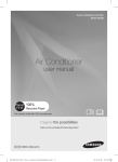
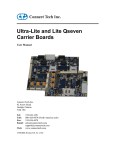
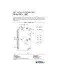
ARMFSC0 ARM9 CPU BOARD w/Freescale i.MX285 (photo) USER’S MANUAL REV 1.1 © CJB ~ August 2015 ARMFSC0_ARM CPUBOARD MANUAL 1.1 page 1 INDEX 1 LIST OF FIGURES ................................................................................................................................................. 3 2 THE C0 CPU BOARD ............................................................................................................................................ 4 2.1 INTRODUCTION ............................................................................................................................................... 4 2.2 FEATURES...................................................................................................................................................... 6 2.3 BLOCK SCHEMATIC ..................................................................................................................................... 7 2.4 TOP SIDE VIEW............................................................................................................................................ 8 2.5 BOTTOM SIDE VIEW .................................................................................................................................... 9 2.6 OVERVIEW OF ONBOARD FEATURES ..........................................................................................................10 2.6.1 RS-485 COM1 PORT ...............................................................................................................................10 2.6.2 COM2 PORT ..........................................................................................................................................10 2.6.3 CANBUS INTERFACE ...............................................................................................................................10 2.6.4 GPIOs ....................................................................................................................................................10 2.6.5 TTL LCD Port ..........................................................................................................................................10 2.6.6 Ethernet Port .........................................................................................................................................10 2.6.7 NO Jumpers ...........................................................................................................................................10 2.6.8 5Vdc Power Supply ................................................................................................................................10 3 POWER RAILS ....................................................................................................................................................11 3.1 4 BACKLIGHT SELECTION...............................................................................................................................11 CONNECTORS ....................................................................................................................................................12 4.1 CONNECTOR TOPOLOGY OF THE C0 CPU BOARD (TOP) ...................................................................................12 4.2 TOPOLOGY OF THE C0 CPU BOARD (BOTTOM) ................................................................................................13 4.2.1 HOW TO RECOGNIZE PIN 1 (CONNECTORS & JUMPERS) .........................................................................13 4.3 DC5V_IN POWER SUPPLY CONNECTOR ......................................................................................................14 4.4 COM1 SERIAL PORT RS485 CONNECTOR ....................................................................................................15 4.4.1 Explanation of RS485 Circuit ..................................................................................................................16 4.4.1.1 Line Termination for COM1 .......................................................................................................................... 16 4.5 USB0, USB1 USB HOST CONNECTORS.........................................................................................................17 4.6 LAN1 FAST ETHERNET CONNECTOR, RJ45...................................................................................................18 4.7 AUDIO CONNECTOR...................................................................................................................................19 4.8 UART_DEBUG PORT ...................................................................................................................................20 4.9 RESET EXTERNAL RESET CONNECTOR.........................................................................................................21 4.10 ENCODER INTERFACE .................................................................................................................................22 4.11 EXP-A I/O CONNECTOR ..............................................................................................................................23 4.12 EXP-B I/O CONNECTOR ..............................................................................................................................24 4.12.1 GPIO Mapping from iMX285..............................................................................................................25 4.13 LCD (BOTTOM SIDE) TTL PANEL FLAT CABLE ................................................................................................26 4.13.1 FLEXIBLE TTL LCD INTERFACE .............................................................................................................27 4.13.1.1 Interface for 4.3” LCD with bonded Resistive Touch Panel (RTP 4W), 480x272 ............................................... 27 4.13.1.2 Interface for 5” LCD with bonded Resistive Touch Panel (RTP 4W), 800x480 .................................................. 28 4.13.1.3 Interface for 5” LCD with bonded PCAP Touch Panel (i2C), 800x480............................................................... 29 4.13.1.4 i2C INTERFACE FOR PCAP TOUCH.................................................................................................................. 30 Notice that there is an auxiliary connector nearby: it is one 6-pin 90º male header, where you can eventually plug an extension cable for the LCD i2C FPC cable. ...................................................................................................................... 30 4.13.1.5 Interface for 7” LCD with Resistive Touch Panel............................................................................................. 31 4.13.2 LED_BL CONNECTOR FOR 7”LCD LED BACKLIGHT.............................................................................32 4.13.3 AUX 4W TOUCH CONNECTOR ............................................................................................................33 4.13.4 EXTENSION CABLES ...........................................................................................................................33 4.14 SD1 (TOP SIDE) µSD MEMORY CARD SOCKET ..............................................................................................34 4.15 BATTERY ....................................................................................................................................................34 ARMFSC0_ARM CPUBOARD MANUAL 1.1 page 2 1 LIST OF FIGURES Fig. 1 Block Schematic................................................................................................................... 7 Fig. 2 Top Side view ...................................................................................................................... 8 Fig. 3 Top Side Dimensions ........................................................................................................... 8 Fig. 4 Bottom Side view ................................................................................................................. 9 Fig. 5 Bottom Side dimensions....................................................................................................... 9 Fig. 6 Preset for onboard LED Driver ........................................................................................... 11 Fig. 7 Topology of the Board (TOP) ............................................................................................. 12 Fig. 8 Topology of the Board (BOTTOM)...................................................................................... 13 Fig. 9 Examples of Silk-Screen figures to recognize Pin 1 ........................................................... 13 Fig. 10 Power Supply Connector: DC_IN .................................................................................... 14 Fig. 11 DC_IN Connector: pin assignment ................................................................................... 14 Fig. 12 Schematic of DC_IN circuitry............................................................................................ 14 Fig. 13 The COM1 Connector ...................................................................................................... 15 Fig. 14 Signals of the COM1 Connector ....................................................................................... 15 Fig. 15 Typical RS485 Driver/Receiver ........................................................................................ 16 Fig. 16 RS485 with TX data instant read-back ............................................................................. 16 Fig. 17 The USB0 and USB1 USB ports (boxed 4-pin headers) ................................................... 17 Fig. 18 Schematic of the Connectors used for USB0 and USB1 .................................................. 17 Fig. 19 RJ45 Ethernet Port........................................................................................................... 18 Fig. 20 Pin Assignment of ETH0 port ........................................................................................... 18 Fig. 21 The Audio Connector ....................................................................................................... 19 Fig. 22 Pin Assignment of the Audio Connector ........................................................................... 19 Fig. 23 Circuitry of the Audio Connector....................................................................................... 19 Fig. 24 The “UART_Debug” Connector ........................................................................................ 20 Fig. 25 Example of USBCOM(TTL1.8V) conversion cable........................................................ 20 Fig. 26 Schematic of the Debug Port Connector .......................................................................... 20 Fig. 27 RESET Connector............................................................................................................ 21 Fig. 28 Schematic of the RESET Connector ................................................................................ 21 Fig. 29 Encoder Interface ............................................................................................................. 22 Fig. 30 Encoder Interface ............................................................................................................. 22 Fig. 31 The EXP-A Connector ...................................................................................................... 23 Fig. 32 The EXP-B Connector ...................................................................................................... 24 Fig. 33 The GPIO mapping .......................................................................................................... 25 Fig. 34 The LCD Connector: designed for instant connection of a small TTL LCD ....................... 26 Fig. 35 The 40pin FPC cable connect the C0 to the TTL LCD ..................................................... 26 Fig. 36 Typical 40 pin connector of a 4.3” LCD with RTP (Resistive Touch Panel) ....................... 27 Fig. 37 Typical 40 pin connector of a 4.3” LCD with RTP (Resistive Touch Panel) ....................... 28 Fig. 38 Typical 40 pin connector of a 4.3” LCD with PCAP Touch Panel ...................................... 29 Fig. 39 The 6-pin ZIF socket for the FPC cable of the PCAP Touch Panel ................................... 30 Fig. 40 Typical 40 pin connector of a 7” LCD with RTP (Resistive Touch Panel) .......................... 31 Fig. 41 The LED_BL connector for powering 7” backlight............................................................. 32 Fig. 42 The 7” LCD and the C0 assembled together .................................................................... 32 Fig. 43 The AUX 4W Touch connector ......................................................................................... 33 Fig. 43 Extension Cable for LCD Backlight................................................................................... 33 Fig. 44 Extension Cable for PCAP Touch..................................................................................... 33 Fig. 45 µSD Flash Card Socket (Bottom Side) ............................................................................. 34 Fig. 46 Battery Insulation foil: how to extract ................................................................................ 34 ARMFSC0_ARM CPUBOARD MANUAL 1.1 page 3 2 THE C0 CPU BOARD (photo) 2.1 Introduction The C0 is a small, cheap but versatile ARM Freescale iMX285 industrial CPU board. It has been designed and manufactured by CJB to provide an entry-level flexible industrial computing core to be used for small touch controllers. A “Controller” is a system where CJB supplies the C0 together with an HMI unit (LCD + touch) and all the necessary software for the appliance’s process management: http://www.cjb.it/en/products/powerplc/powerplcbridge CJB provides an extensive Graphic User Interface s/w support for QT-Library (Embedded Linux). Despite the cheap and small design, the C0 drives a number of peripheral interfaces thanks to its versatile I/O features: Ethernet and serial COM port (RS485) for Modbus, CAN for CANopen modules (CAN port needs external signal conditioning and driver interface mini-board). The board has also 18 onboard GPIOs (TTL level) which can be easily conditioned (also externally) for local I/O management. Two pin-headers which group both power supply rails, GPIOs and SPI/i2C buses allow the C0 to be plugged onto a customizable carrier-board (which could host all the I/O peripherals like relays, temperature interfaces, and so on), or they can carry a small piggy board with minimal I/O interface devices. The goal is to provide a small handy, cheap and highly reliable controller to be used in appliances where cost saving is mandatory. The CPU Board design will allow some typical usages: a) Stand-alone controller with or without display to be used with side-by-side I/O modules in a daisy-chain connection like below: C0 The modules can be connected by a short flat cable: b) Piggy-back over/under an I/O carrier-board or also stacked I/O modules. C0 In this case the C0 can either feed power to the piggy board, or receive power from it. But the C0 can also find its best environment if used as a small Touch-Controller. See next page. ARMFSC0_ARM CPUBOARD MANUAL 1.1 page 4 c) HMI Controller matched to a small LCD display (with RTP or PCAP touch, from 4.3” to 7”), remotely connected to I/O boards through RS485 Modbus-RTU: Remote Modbus I/O Module LCD/TOUCH Metal Plate CPUboard C0 This can really be the best usage since the great versatility of the C0 matched to the cheap but performing LCD make a nice but cheap Touch-Controller, which can be used in small to medium appliances. The power supply to the C0 is DC 5V +/-5% and the operating temperature is -40ºC ~ +85ºC (the actual range may be limited by the temperature range of the display). All above features make the C0 the most reliable and versatile choice for low-end applications like: - Professional food appliances Small Vending machines (especially outdoor) Parking, ticketing machines (especially outdoor) Small distributed touch-controllers for building & home automation © CJB 2015 ARMFSC0_ARM CPUBOARD MANUAL 1.1 page 5 2.2 Features The C0 Freescale iMX285 (Automotive) ARM926EJ-S™ CPU board has these features: • • • • • • • • • • • • • • • • • • • • • • Freescale iMX285 (454 MHz) http://www.freescale.com/webapp/sps/site/prod_summary.jsp?code=i.MX285 256MB (128MB) DDR2 RAM onboard 1x 64kB SPI-RAM (static) for permanent storage of data with unlimited write cycles, with battery backup (uses the same battery which keeps the Real Time Clock running) 2x UARTS: o 1x RS485 (not insulated) o 1x general purpose TTL COM port, not insulated, which has TX, RX, RTS and CTS and needs external signal conditioning 2x USB ports with 4-pin headers 1x Ethernet 10/100 with RJ45 90º socket 1x push-push socket for µSD flash card 1x LCD Interface with a 40pin ZIF socket for FPC cable, to support 40pin FPC cables of new generation of small TTL LCD panels (4.3” 480x272, 5” 480x272 and 800x480, 7” 800x480) with LED backlight and eventually with bonded resistive or capacitive touch 1x 4W resistive touch panel (RTP) interface for the touch screen (signals are in the same FPC cable of the LCD cable but also available on a separate pin-header) 1x i2C PCAP touch interface, with dedicated 6pin FPC cable ZIF connector (same signals are also available on a separate pin-header) 1x LED Backlight driver for the LCD with selectable current values 2x pin-headers for functional expansion. They deliver power, GPIO’s and SPI & i2C buses to external conditioning boards (if needed). 18x TTL GPIO’s, software selectable as Inputs or Outputs. Need external signal conditioning. 1x CANbus interface, TTL, to be conditioned with external driver circuit 1x AUDIO interface, with mono signal generated by PWM digital I/O for simple sounds. Same signal level of a standard Line-Out signal 1x ENCODER “Resolver” interface with pushbutton: this is a dedicated interface for a 5V powered resolver (knob rotation clockwise/counterclockwise detection device, with integrated pushbutton). This kind of knob is very common in small food appliances to be used for setting a value (e.g.: a time, a temperature), increasing or decreasing it and confirming the setting by pressing the pushbutton. The interface is fully protected against transients. 1x RTC (Real Time Clock) Low-Power. Based on the same M41T0 used in our C2 (iMX53) board, it only drains 1 µA from the battery 1x CR2032 Lithium Battery with battery socket, to give power to both the RTC and the SPI Static RAM Power-Supply: single 5Vdc +/-5%. Power consumption depends on the LCD panel attached to the board. Some examples here below show the power needed, assuming there are no loads on the USB ports. Power need includes RS485, Ethernet, and all active devices on board. 4.2W with 4.3” RTP 4.3W with 5” RTP 4.7W with 5” PCAP 5.7W with 7” RTP 6.3W with 7” PCAP Dimensions: “PICO” form factor, 100x72mm Operating System: Embedded Linux Certifications: CE. Verified for FCC-B. Following page shows the block schematic of the CPU board. ARMFSC0_ARM CPUBOARD MANUAL 1.1 page 6 2.3 BLOCK SCHEMATIC Fig. 1 Block Schematic ARMFSC0_ARM CPUBOARD MANUAL 1.1 page 7 2.4 TOP SIDE VIEW Expansion-B (GPIO, i2C, SPI, Power) Expansion-A (GPIO, i2C, SPI, Power) Audio 256MB RAM Ethernet iMX285 µSD 5VDC_IN Battery Reset USB0 JTAG USB1 RS485 Encoder Debug Fig. 2 Top Side view Fig. 3 Top Side Dimensions ARMFSC0_ARM CPUBOARD MANUAL 1.1 page 8 2.5 BOTTOM SIDE VIEW 7” Backlight LCD TTL PCAP AUX PCAP AUX 4W Touch Fig. 4 Bottom Side view Fig. 5 Bottom Side dimensions ARMFSC0_ARM CPUBOARD MANUAL 1.1 page 9 2.6 OVERVIEW OF ONBOARD FEATURES 2.6.1 RS-485 COM1 PORT The 1st UART (COM1) is set as RS485 only, and is the main peripheral interface port which will communicate (e.g.: by Modbus-RTU) with external peripherals. This port uses UART4 interface. 2.6.2 COM2 PORT The 2nd UART (COM2) is a general purpose COM port interface, TTL level, which needs conditioning before usage (carrier board or piggy board). This port uses UART0 interface. 2.6.3 CANBUS INTERFACE The board has a CANbus port, made from the native CANbus interface of the iMX285. It is TTL, needs external conditioning to be used. This port uses CAN0 channel of the iMX285. 2.6.4 GPIOs 18 TTL (3.3V) GPIOs are wired mostly to a 44-pin header connector, others to the 20-pin header connector, and can be used for an external I/O conditioning board (user’s designed). All GPIOs come from direct GPIO ports of the iMX285. 2.6.5 TTL LCD Port This 24Bit TTL LCD port is designed to make a snap connection through a 40pin FPC cable for standard 4.3” or 5” or 7” small LCD panels with LED backlight. A suitable LED driver for such panels is provided onboard or is powered by the same main 5Vdc. 2.6.6 Ethernet Port There is one 10/100Mb Ethernet Ports available from RJ45 connectors. It uses the ENET0 channel of the processor. 2.6.7 NO Jumpers Since the C0 is going to be used mostly in vibrating appliance applications, jumpers may be a weak point. So we have designed it for jumper-less application. Hence, the RS485 termination is permanently connected, and the Battery is kept isolated by a plastic foil which can be pulled out and removed only when the board is set to work. LCD panel backlight current selection is made by solder pads for preset. 2.6.8 5Vdc Power Supply The board can is powered by 5Vdc +/-5% which may come from an external AC-DC adaptor, or may be generated onboard by the I/O board which will be controlled by the same C0. ARMFSC0_ARM CPUBOARD MANUAL 1.1 page 10 3 POWER RAILS There are three main power rails for the C0: • • • +5Vdc +3.3Vdc +1.8Vdc Main Power Supply from external source Internal Rail, also available from the extension pin-headers Internal Rail, mainly used for the DDR2 RAM The DC_IN supply must be within +5Vdc +/-5% range. 3.1 BACKLIGHT SELECTION Before connecting the LCD panel you must preset the onboard LED Driver for the correct current & voltage. SP1, SP2 and SP3 are three jumper-pads which must be shorted (only one of the three) with a drop of solder. The default preset is for 5” LCD 800x480 with i2C PCAP touch. Fig. 6 Preset for onboard LED Driver ARMFSC0_ARM CPUBOARD MANUAL 1.1 page 11 4 CONNECTORS 4.1 CONNECTOR TOPOLOGY of the C0 CPU Board (TOP) Please always refer to the board TOP topology as from below drawing. Expansion-A (GPIO, i2C, SPI, Power) UPPER SIDE Expansion-B Audio AUX RTP Ethernet 256MB RAM RIGHT SIDE LEFT SIDE iMX285 µSD 5VDC_IN Battery Reset JTAG USB0 USB1 RS485 Encoder Debug LOWER SIDE Fig. 7 Topology of the Board (TOP) ARMFSC0_ARM CPUBOARD MANUAL 1.1 page 12 4.2 TOPOLOGY of the C0 CPU Board (BOTTOM) Please always refer to the board BOTTOM topology as from below drawing. Since we’re looking at the board from bottom side, LEFT and RIGHT sides are reversed. Fig. 8 Topology of the Board (BOTTOM) 4.2.1 HOW TO RECOGNIZE PIN 1 (CONNECTORS & JUMPERS) To recognize Pin 1 of Connectors & Jumpers, the rules are the following: 1) 2) 3) 4) 5) Pin 1 of Jumpers is evidenced by a bold square around Pin 1 of Connectors is evidenced by a bold marking at side of Pin 1 Underneath (BOTTOM Side) Pin 1 has always a square pad (others have round pads) In most cases, where there is room, pins are numbered. In other connectors, a “triangle” identifies Pin 1. Fig. 9 Examples of Silk-Screen figures to recognize Pin 1 ARMFSC0_ARM CPUBOARD MANUAL 1.1 page 13 4.3 DC5V_IN POWER SUPPLY CONNECTOR The DC5V_IN connector is a 2-pin 3.5mm connector and it’s placed in the mid of left side. Fig. 10 Power Supply Connector: DC_IN Pin assignment is from right to left (looking from front): 1 = +5Vdc 2 = GND 2 1 Fig. 11 DC_IN Connector: pin assignment This is the schematic portion. Notice the soldered fuse (Fuse 1) near the connector. Fig. 12 Schematic of DC_IN circuitry Note the fuse and the circuitry to cut the power when the reset is triggered. Removing the 5Vdc ensures the board will restart in the correct way. Be careful to avoid any DC5V_IN polarity inversion. ARMFSC0_ARM CPUBOARD MANUAL 1.1 page 14 4.4 COM1 SERIAL PORT RS485 CONNECTOR This is placed at bottom side, near the battery. It is a 3-pin 2.0mm boxed pin-header. Fig. 13 The COM1 Connector Circuit and pin assignment is defined here below: PIN 1 PIN 2 PIN 3 DATA+ DATAGROUND Fig. 14 Signals of the COM1 Connector ARMFSC0_ARM CPUBOARD MANUAL 1.1 page 15 4.4.1 Explanation of RS485 Circuit The COM1 port is permanently set for RS485 communication: • RS485 Half Duplex only. When you transmit you cannot receive. Two wires only: Data+ and Data-. Differential signals to allow a very high noise rejection. Allows communication over long distance. The major problem of an RS485 communication is that when the transmit driver is on, the receiver is off since they are driven by the same control signal (RTS): direct for TX and inverted for RX. RX DATA- RTS DATA+ TX Fig. 15 Typical RS485 Driver/Receiver This is not so good because you cannot understand when the TX flux has ended and you can exchange the direction of the driver/receiver (changing the level of RTS). In some cases this is enough, but in many others you need to understand quickly when it’s time to change the direction. Then, you have to use the circuit below: 3 RX 4 DATARTS DATA+ 1 TX 2 Fig. 16 RS485 with TX data instant read-back The RX receiver is always enabled while you enable the TX driver only when you need to transmit. Since the RX receiver is always enabled, you will read your TX’ed data as soon as it exits from the driver. 4.4.1.1 Line Termination for COM1 The termination resistor (R121) is permanently connected. So the C0 must be used as first or last node of the RS485 communication line. ARMFSC0_ARM CPUBOARD MANUAL 1.1 page 16 4.5 USB0, USB1 USB HOST CONNECTORS They are placed near lower side, near the battery socket. They are 4-pin boxed headers 2.0mm. Fig. 17 The USB0 and USB1 USB ports (boxed 4-pin headers) PIN ASSIGNMENT: 1 2 3 4 VCC (red wire) DATA- (white wire) DATA+ (green wire) GND (black wire) Fig. 18 Schematic of the Connectors used for USB0 and USB1 The USB interface is protected by a PTC fuse. The current available from pin1 of each connector (Vcc) depends on the 5Vdc input connected power. If the external 5Vdc can deliver enough power, you can drain max 500mA from each port. ARMFSC0_ARM CPUBOARD MANUAL 1.1 page 17 4.6 LAN1 FAST ETHERNET CONNECTOR, RJ45 There is one RJ45 connector for onboard Ethernet channel #0, placed at left side. ETH0 ETH0 Fig. 19 RJ45 Ethernet Port The signals of this port follow the standard assignment, as you can see here below. TX+ TXRX+ RX- Fig. 20 Pin Assignment of ETH0 port The MACaddress for the port has been programmed in factory; the value is the label stuck onto the RJ45 connector block. ARMFSC0_ARM CPUBOARD MANUAL 1.1 page 18 4.7 AUDIO CONNECTOR There is one 2-pin boxed header, 2.0mm for the Audio Line-Out signal, which is on the lower side. Fig. 21 The Audio Connector This connector has a Mono output generated by the PWM1 GPIO (pin K4) of the processor. It can be used for simple sounds. 1 = Line_Out Mono 2 = GND Fig. 22 Pin Assignment of the Audio Connector Fig. 23 Circuitry of the Audio Connector WARNING: Never use the Line_OUT signal to drive a speaker or a headphone. The signal is a low power audio signal and need always to be amplified externally. ARMFSC0_ARM CPUBOARD MANUAL 1.1 page 19 4.8 UART_DEBUG PORT To survey the boot up of the board, you must connect the “Debug” port to a PC, where a suitable “Console Simulator” program is running. For example: PUTTY or HyperTerminal or other similar programs. Fig. 24 The “UART_Debug” Connector Since modern PC’s do not have COM ports, it’s suggested to use an USBCOM (TTL3.3V) conversion cable, like the FTDI model TTL-232RG-VREG3V3-WE, which TTL signals commit the 3.3Vdc levels required by the C2 Debug Port. Such cable appears like the photo here below (where we have already wired the small white connector for the Debug Port). Fig. 25 Example of USBCOM(TTL1.8V) conversion cable The schematic of the Debug Port is here below: 1 2 3 4 5 6 Nc Nc GND TX TTL 1.8V GND RX TTL 1.8V Fig. 26 Schematic of the Debug Port Connector When preparing the cable, wire one JST B6B-PH-K 6-pin female so that the TX wire of the conversion cable is connected to pin 6 (RX), the RX wire of the cable is connected to pin 4 (TX), and the Ground wire is connected to pin 3. The 3.3Vdc wire usually provided by the cable must not be connected. ARMFSC0_ARM CPUBOARD MANUAL 1.1 page 20 4.9 RESET EXTERNAL RESET CONNECTOR This connector is a 2-pin boxed header, 2.0mm pitch, available for external reset. Fig. 27 RESET Connector Fig. 28 Schematic of the RESET Connector Shorting the two pins of the RESET connector makes hardware cold-reset sent immediately to the board. The pin assignment is the following: Pin 1 = GND ARMFSC0_ARM CPUBOARD MANUAL 1.1 Pin 2 = Reset page 21 4.10 ENCODER INTERFACE This is a 6-pin boxed header, 2.0mm, at right side between the Expansion-B and the µSD socket. Fig. 29 Encoder Interface This is an interface for a common 5V “Rotary Encoder” (sometimes called “Resolver” by some users) with pushbutton. This is generally used not to count the pulses, but to distinguish the rotation versus, so that the management software can “increase” the current value (e.g.: a temperature displayed on the screen) if a clockwise rotation is detected, or decrease it (if a counter-clockwise rotation is detected). The pushbutton is activated pushing the knob, and when the push action is detected, then the actual value is “confirmed”, and the software can move to next value to be adjusted. The Encoder interface schematic is displayed here below. Fig. 30 Encoder Interface ARMFSC0_ARM CPUBOARD MANUAL 1.1 page 22 4.11 EXP-A I/O CONNECTOR This is a 44pin 2.0mm male header which gathers a number of TTL signals to be used for expanding the C0 board. Hence, this header can be used to bring the signals to a piggy board or to a carrier board. Fig. 31 The EXP-A Connector Pin assignment of the EXP-A Connector is the following: Pin 1 3 5 7 9 11 13 15 17 19 21 23 25 27 29 31 33 35 37 39 41 43 Signal CAN_TX_0 (GPIO_22) 5VOUT_EXP UART0_TX UART0_RTS 5VOUT_EXP EXP_A_SCL 5VOUT_EXP SSP2_SS0 SSP2_MISO 3.3VOUT_EXP 5VOUT_EXP GPIO0_0 GPIO0_2 GPIO0_4 GPIO0_6 GPIO0_16 GPIO0_18 GPIO0_24 GPIO0_26 5VDC_IN 5VDC_IN GROUND Pin 2 4 6 8 10 12 14 16 18 20 22 24 26 28 30 32 34 36 38 40 42 44 Signal CAN_RX_0 (GPIO_23) GROUND UART0_RX UART0_CTS GROUND EXP_A_SDA GROUND SSP2_SS1 SSP2_MOSI SSP2_SCLK GROUND GPIO0_1 GPIO0_3 GPIO0_5 GPIO0_7 GPIO0_17 GPIO0_19 GPIO0_25 GPIO3_26_PWM1 5VDC_IN 5VDC_IN GROUND The GPIO signals provide 3.3Vdc levels, and need to be conditioned externally (unless they are connected to TTL devices). All GPIO’s have a 10K pull-up resistor to +3.3Vdc. ARMFSC0_ARM CPUBOARD MANUAL 1.1 page 23 4.12 EXP-B I/O CONNECTOR This is a 20pin 2.0mm pitch male header placed at right side of the board, which gathers a number of TTL signals to be used for expanding the C0 board. Hence, this header can be used to bring the signals to a side-by-side I/O board or to a carrier board or to a piggy board. Fig. 32 The EXP-B Connector Pin assignment of the EXP-B Connector is the following: Pin 1 3 5 7 9 11 13 15 17 19 Signal SSP2_MISO SSP2_SCLK SSP2_SS0 EXP_A_SDA EXP_A_SCL GPIO0_0 GPIO0_2 GPIO0_4 5VOUT_EXP 3.3VOUT_EXP Pin 2 4 6 8 10 12 14 16 18 20 Signal GROUND SSP2_MOSI SSP2_SS1 GROUND GPIO0_21 GPIO0_1 GPIO0_3 GPIO3_29_PWM4 5VOUT_EXP GROUND The GPIO signals provide 3.3Vdc levels, and need to be conditioned externally (unless they are connected to TTL devices). All GPIO’s have a 10K pull-up resistor to +3.3Vdc. ARMFSC0_ARM CPUBOARD MANUAL 1.1 page 24 4.12.1 GPIO Mapping from iMX285 The table which follows shows the mapping of the resources which come from the iMX285 ARM processor and are brought to the 20-pin and to the 44-pin Connectors of the C0. 20-pin HEADER Pin # Wire Description CPU PAD ALT Bit Port Position Address CPU PAD ALT Bit Port Position Address 1 3 4 5 6 7 9 10 11 12 13 14 15 16 44-pin HEADER Pin # Wire Description 1 2 5 6 7 8 11 12 15 16 17 18 20 23 24 25 26 27 28 29 30 31 32 33 34 35 36 37 38 Fig. 33 The GPIO mapping ARMFSC0_ARM CPUBOARD MANUAL 1.1 page 25 4.13 LCD (BOTTOM SIDE) TTL PANEL FLAT CABLE This is a ZIF 40 pin FPC (flex PCB Cable) connector for a 24-bit RGB TTL 4.3” or 5” or 7” LCD panel. It’s placed at bottom side of PCBA. Its position has been designed so that the FPC Cable of the LCD can be easily plugged in, so the board and the LCD can then be “sandwiched together”. Fig. 34 The LCD Connector: designed for instant connection of a small TTL LCD The connector has a hinged brown clip which can be raised (gently) with a fingernail. Then the FPC cable must be carefully slid in the connector with the brown clip kept opened. The stiffener side of the FPC cable must stay on top. Then the brown clip has to be pushed downward (gently) to keep the FPC cable firmly in place. The result will look like the image here below. (photo) Fig. 35 The 40pin FPC cable connect the C0 to the TTL LCD As you can see, the connection is straightforward, and when the C0 is rotated over the LCD (to make a “sandwich”) the FPC cable has plenty of ease to bend without any risk of damage. ARMFSC0_ARM CPUBOARD MANUAL 1.1 page 26 4.13.1 FLEXIBLE TTL LCD INTERFACE Many models of small TTL LCD panels can be connected. CJB will suggest the correct models and will also provide them to you. The C0 can support both the supply for the LED backlight, and the 4W resistive touch interface, and the PCAP touch through a dedicated 6-pin ZIF socket. 4.13.1.1 Interface for 4.3” LCD with bonded Resistive Touch Panel (RTP 4W), 480x272 Pin No. Symbol Description 1 VLED- Cathode of LED backlight 2 VLED+ Anode of LED backlight 3 GND Power ground 4 VDD Power voltage 5 R0 Red data (LSB) 6 R1 Red data 7 R2 Red data 8 R3 Red data 9 R4 Red data 10 R5 Red data 11 R6 Red data 12 R7 Red data (MSB) 13 G0 Green data (LSB) 14 G1 Green data 15 G2 Green data 16 G3 Green data 17 G4 Green data 18 G5 Green data 19 G6 Green data 20 G7 Green data(MSB) 21 B0 Blue data(LSB) 22 B1 Blue data 23 B2 Blue data 24 B3 Blue data 25 B4 Blue data 26 B5 Blue data 27 B6 Blue data 28 B7 Blue data(MSB) 29 GND Power ground 30 DCLK Pixel clock 31 DISP Display on/off 32 HSYN Horizontal sync signal 33 VSYNC Vertical sync signal 34 DE Data enable 35 NC NO connect 36 GND Power ground 37 XR Touch panel pin 38 YB Touch panel pin 39 40 XL YT Notice that Pins 1 and 2 are the supply for the LED backlight which must come from the onboard DCDC which can provide a constant current source. On small LCD panels, the FPC cable traces are very thin, so the trick is to provide low current at high voltage to supply the LEDs. Last 4 pins are the signals of the Resistive Touch Panel. Touch panel pin Touch panel pin Fig. 36 Typical 40 pin connector of a 4.3” LCD with RTP (Resistive Touch Panel) ARMFSC0_ARM CPUBOARD MANUAL 1.1 page 27 4.13.1.2 Interface for 5” LCD with bonded Resistive Touch Panel (RTP 4W), 800x480 Pin No. Symbol Description 1 VLED- Cathode of LED backlight 2 VLED+ Anode of LED backlight 3 GND Power ground 4 VDD Power voltage 5 R0 Red data (LSB) 6 R1 Red data 7 R2 Red data 8 R3 Red data 9 R4 Red data 10 R5 Red data 11 R6 Red data 12 R7 Red data (MSB) 13 G0 Green data (LSB) 14 G1 Green data 15 G2 Green data 16 G3 Green data 17 G4 Green data 18 G5 Green data 19 G6 Green data 20 G7 Green data(MSB) 21 B0 Blue data(LSB) 22 B1 Blue data 23 B2 Blue data 24 B3 Blue data 25 B4 Blue data 26 B5 Blue data 27 B6 Blue data 28 B7 Blue data(MSB) 29 GND Power ground 30 DCLK Pixel clock 31 DISP Display on/off 32 HSYN Horizontal sync signal 33 VSYNC Vertical sync signal 34 DE Data enable 35 NC NO connect 36 GND Power ground 37 XR Touch panel pin 38 YB Touch panel pin 39 40 XL YT Notice that Pins 1 and 2 are the supply for the LED backlight which must come from the onboard DCDC which can provide a constant current source. On small LCD panels, the FPC cable traces are very thin, so the trick is to provide low current at high voltage to supply the LEDs. Last 4 pins are the signals of the Resistive Touch Panel. Touch panel pin Touch panel pin Fig. 37 Typical 40 pin connector of a 4.3” LCD with RTP (Resistive Touch Panel) ARMFSC0_ARM CPUBOARD MANUAL 1.1 page 28 4.13.1.3 Interface for 5” LCD with bonded PCAP Touch Panel (i2C), 800x480 Pin No. Symbol Description 1 VLED- Cathode of LED backlight 2 VLED+ Anode of LED backlight 3 GND Power ground 4 VDD Power voltage 5 R0 Red data (LSB) 6 R1 Red data 7 R2 Red data 8 R3 Red data 9 R4 Red data 10 R5 Red data 11 R6 Red data 12 R7 Red data (MSB) 13 G0 Green data (LSB) 14 G1 Green data 15 G2 Green data 16 G3 Green data 17 G4 Green data 18 G5 Green data 19 G6 Green data 20 G7 Green data(MSB) 21 B0 Blue data(LSB) 22 B1 Blue data 23 B2 Blue data 24 B3 Blue data 25 B4 Blue data 26 B5 Blue data 27 B6 Blue data 28 B7 Blue data(MSB) 29 GND Power ground 30 DCLK Pixel clock 31 DISP Display on/off 32 HSYN Horizontal sync signal 33 VSYNC Vertical sync signal 34 DE Data enable 35 NC NO connect 36 GND Power ground 37 38 39 40 Notice that Pins 1 and 2 are the supply for the LED backlight which must come from the onboard DCDC which can provide a constant current source. On small LCD panels, the FPC cable traces are very thin, so the trick is to provide low current at high voltage to supply the LEDs. Last 4 pins are the signals of the Resistive Touch Panel. Fig. 38 Typical 40 pin connector of a 4.3” LCD with PCAP Touch Panel The PCAP touch interface is i2C and requires a dedicated ZIF connector (6-pin). ARMFSC0_ARM CPUBOARD MANUAL 1.1 page 29 4.13.1.4 i2C INTERFACE FOR PCAP TOUCH The small 6-pin ZIF in bottom side can host the FPC cable of the PCAP touch. Fig. 39 The 6-pin ZIF socket for the FPC cable of the PCAP Touch Panel The i2C interface needs the following signals: Pin 1 2 3 4 5 6 Signal Touch_Reset (GPIO0_27) Touch Interrupt (GPIO0_28) PCAP_SDA PCAP_SCL GROUND +3.3Vdc Notice that there is an auxiliary connector nearby: it is one 6-pin 90º male header, where you can eventually plug an extension cable for the LCD i2C FPC cable. This is useful when the size of the LCD (e.g.: 7”) does not allow a direct “snap-in connection” like that has been designed for the 5” PCAP panel. ARMFSC0_ARM CPUBOARD MANUAL 1.1 page 30 4.13.1.5 Interface for 7” LCD with Resistive Touch Panel The compatible 7” TTL panel with onboard bonded resistive touch cannot get the LED power from the two small traces of the FPC cable, so the LED backlight power is supplied by the LED_BL connector which is placed at bottom side of the C0 board. Pin No. Symbol Description 1 2 3 GND Power ground 4 VDD Power voltage 5 R0 Red data (LSB) 6 R1 Red data 7 R2 Red data 8 R3 Red data 9 R4 Red data 10 R5 Red data 11 R6 Red data 12 R7 Red data (MSB) 13 G0 Green data (LSB) 14 G1 Green data 15 G2 Green data 16 G3 Green data 17 G4 Green data 18 G5 Green data 19 G6 Green data 20 G7 Green data(MSB) 21 B0 Blue data(LSB) 22 B1 Blue data 23 B2 Blue data 24 B3 Blue data 25 B4 Blue data 26 B5 Blue data 27 B6 Blue data 28 B7 Blue data(MSB) 29 GND Power ground 30 DCLK Pixel clock 31 DISP Display on/off 32 HSYN Horizontal sync signal 33 VSYNC Vertical sync signal 34 DE Data enable 35 NC NO connect 36 GND Power ground 37 XR Touch panel pin 38 YB Touch panel pin 39 40 XL YT Last 4 pins are the signals of the Resistive Touch Panel. The LED backlight has a separate, independent connector (LED_BL), where the suitable Power must be supplied. The C0 has been designed to supply such power for the LCD’s LED backlight. Touch panel pin Touch panel pin Fig. 40 Typical 40 pin connector of a 7” LCD with RTP (Resistive Touch Panel) ARMFSC0_ARM CPUBOARD MANUAL 1.1 page 31 4.13.2 LED_BL CONNECTOR FOR 7”LCD LED BACKLIGHT Just near the 40 pin LCD FPC connector there is the LED_BL connector, which is a special 2-pin socket (horizontal) into which the LED Backlight connector of the 7” LCD will fit. Fig. 41 The LED_BL connector for powering 7” backlight Notice that if you design your assembly so that the C0 will stay as a “sandwich” together with the LCD, the position of this connector has been chosen so that you can directly connect the original LCD backlight cable directly, and this saves costs. See, for example, the assembly below. (photo) Fig. 42 The 7” LCD and the C0 assembled together ARMFSC0_ARM CPUBOARD MANUAL 1.1 page 32 4.13.3 AUX 4W TOUCH CONNECTOR This is a 4-pin header where you can connect the touch panel FPC through a suitable extension cable, when the size of the panel does not allow a direct “snap-in connection” through the same 40pin FPC cable. Fig. 43 The AUX 4W Touch connector 4.13.4 EXTENSION CABLES CJB can provide suitable extension cables for both the i2C PCAP touch and for the LED backlight, in case you need to use a 7” panel with PCAP. Fig. 44 Extension Cable for LCD Backlight Fig. 45 Extension Cable for PCAP Touch ARMFSC0_ARM CPUBOARD MANUAL 1.1 page 33 4.14 SD1 (TOP SIDE) µSD MEMORY CARD SOCKET This socket can host one µSD flash memory card and it is a push-push type socket. Fig. 46 µSD Flash Card Socket (Bottom Side) 4.15 BATTERY The C0 hosts one CR2032 standard battery. This is used to power the RTC (Real Time Clock) and the SPI 64kB RAM. The battery is isolated from the socket with a foil which can be extracted before setting the C0 to use. The battery will supply power only after the foil has been extracted. Fig. 47 Battery Insulation foil: how to extract © CJB 2015 ARMFSC0_ARM CPUBOARD MANUAL 1.1 page 34