1
Telemetry Box Rev 1.0
User manual
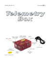
Figure 1: Telemetry Box
1
Telemetry Box Rev 1.0
User manual
General index
1 Contents of the selling pack.............................................................................................................4
2 General description...........................................................................................................................4
3 Quickstart audio playback for the impatient....................................................................................5
4 Telemetry Box's components description.........................................................................................6
5 Operation description.......................................................................................................................8
5.1 Telemetry Box supply...............................................................................................................8
5.2 Lap time playback.....................................................................................................................9
5.3 Data storage on the Telemetry Box's internal memory...........................................................10
5.3.1 Erase stored data.............................................................................................................13
5.4 Audio language updating........................................................................................................13
5.5 Telemetry Box firmware updating.........................................................................................14
5.6 Use of the PC chronometer function.......................................................................................14
5.7 Use of the Telemetry live function..........................................................................................14
6 Telemetry Box assembly on SCP-01 controller.............................................................................15
7 System diagnostics.........................................................................................................................20
8 Telemetry Box firmware updating procedure.................................................................................20
9 Contents of the selling pack...........................................................................................................33
10 General description.......................................................................................................................33
11 Description of the Track Interface................................................................................................34
12 Track Interface power supply.......................................................................................................36
13 Track Interface connections..........................................................................................................36
13.1 Connection to a DS bridge....................................................................................................36
13.2 Connection to a DS chrono...................................................................................................36
13.3 Connection to a dead strip....................................................................................................37
13.4 Connection to Slot.it SCP-01 controller...............................................................................40
13.5 Connection to the Slot.it Telemetry Box...............................................................................41
13.6 Connection to other Track Interfaces....................................................................................41
14 Track Interface setting..................................................................................................................44
14.1 Setting: DS bridge lap counter sensor, dead strip sector sensor...........................................45
14.2 Setting: DS bridge sector sensor, dead strip lap counter sector............................................45
14.3 Setting: DS bridge sector sensor, dead strip sector sensor....................................................45
14.4 Not allowed Setting..............................................................................................................46
15 Installation of TelBoxPCIntRunTime...........................................................................................50
16 Use of the Telemetry Box PC Interface application.....................................................................50
16.1 Driver installation.................................................................................................................50
16.2 Use of the Telemetry Box PC Interface application to communicate with the Telemetry
Box.................................................................................................................................................52
16.2.1 Use the application to communicate with the Telemetry Box......................................54
16.2.1.3 Download Language function...............................................................................56
16.2.1.4 Download telemetry data function........................................................................56
16.2.1.5 Erase stored data function.....................................................................................57
16.2.1.6 Telemetry function.................................................................................................57
16.2.1.7 Postprocessing function.........................................................................................59
2
Telemetry Box Rev 1.0
User manual
Warranty: two years. We retain the right to reject under warranty repairs of Telemetry box showing
signs of tampering and/or not accompanied by the repair application (downloadable at www.slot.it )
totally filled in. This product is in accordance with RoHS guidelines. Do not dip it into water and do
not put it in the microwave oven.
The product has not been tested on animals, also because they would not understand the meaning of
"Lap time" .
Completely conceived, thought up and realized by Maurizio Ferrari, Maurizio Gibertoni, Cristian
Anceschi and Stefano Giorgi of Galileo Engineering S.r.l. Via F. Cavallotti, 16 – 41122 Reggio
Emilia, Italy – www.slot.it – [email protected]
Slot.it and Slot.it logo are registered trademarks by Galileo Engineering S.r.l.
We thank you for choosing the Telemetry Box system. Before operating, please read this manual
attentively.
Warning: improper use, at high volume and for a long time, can damage the auditory apparatus.
3
Telemetry Box Rev 1.0
User manual
1 Contents of the selling pack
In the package are the following objects:
1. A Telemetry Box;
2. A connection cable for the signals coming from the Track Interface, to be (optionally)
linked up with the cartridge of the controller SCP-01;
3. A quick start user manual.
2 General description
Telemetry Box is an innovative timing system that allows to:
•
reproduce via audio the lap times recorded by the pilot, in a language to be chosen among
many;
•
store in the device’s internal memory the times heard on earphones, sector times and in case
the telemetry data of the SCP button of Slot.it to which it is connected;
•
listen to your favourite music while driving, by connecting the Telemetry Box to a MP3
player though a normal audio cable not included in the package;
•
download the stored data that can be looked up by the user from a PC by means of a special
program downloadable for free (we’re generous, aren’t we?) at www.slot.it (Telemetry Box
PC Interface);
•
update the software of the system, with the opportunity to add new specifications to the
Telemetry Box in the future without any additional charge;
•
delete stored data (good idea);
•
remember the status of data storage button and mute button so that it is not necessary to
repeat the setup carried out before the supply was cut off.
Moreover, Telemetry Box is a versatile system, since its functioning requires only the presence of
the Track Interface and is totally independent of the kind of controller employed.
The presence of the Track Interface is necessary since the latter has the job of interfacing the
Telemetry Box with the track by collecting the signals coming from the sensors on the circuit (DS
bridge, dead strip, Winchrono,...) and sending them after suitable elaboration to the Telemetry Box
itself. For further information concerning the Track Interface system, see the relative manual.
4
Telemetry Box Rev 1.0
User manual
3 Quickstart audio playback for the impatient
Connect the Track Interface to your track’s sensors according to the relative manual.
Connect the Telemetry Box to the Track Interface through the “Track to Telemetry” cable. Connect
the power supply to the Track Interface.
IMPORTANT: Before using the telemetry box for the first time, an “Erase stored data” operation
must be performed (please refer to § 5.3.1), else the box will behave as if its memory was already
full. This does not apply if you change language from the default English as the language change
erases all stored data.
Make sure that the LED near the “Red = Audio off” label is off. Adjust the volume.
Check, by passing a car over the lap or sector sensor(s), that the Track Interface and the Telemetry
Box receive their signals (LED flashing on both boxes: yellow or green on the Track Interface,
green on the Telemetry Box).
At this point, you’re playing with the cars, your lap times are transmitted in your earphones, your
driving has improved, and you've promised yourself to read the manual afterwards. It always
happens, but nobody ever really reads the instructions. What a pity. There are many other features
that we engineers love to put in products, and, weirdly, we are paid for doing it. The Telemetry Box
is no exception and without a thorough reading of the manual it is very difficult to make the best
use of all its features. It stands to reason that if nobody reads the manual many features of the
product do not come to light and turn out to be useless. Then, why develop them? Does not this
render the engineers’ role useless? So please, save the engineers and read the manual.
5
Telemetry Box Rev 1.0
User manual
4 Telemetry Box's components description
Figure 3: Telemetry Box: seen from the rear.
Figure 2: Telemetry Box: seen of above.
Figure 5: Telemetry Box: seen from the left side.
Figure 4: Telemetry Box: seen from the right side.
Figure 6: Connection cable.
6
Telemetry Box Rev 1.0
User manual
With reference to the previous pictures of the Telemetry Box, the following components can be
distinguished:
1. mute switch: it enables/disables Lap Time Playback;
2. “Mem on/off” button: it has two functions:
•
simple pressure: it enables/disables telemetry data storage and/or lap time
storage in the Telemetry Box's internal memory;
•
pressed down for at least 4 seconds: it enables the deletion of stored data.
This operation can be carried out only when the Telemetry Box is not connected to
the PC. Otherwise, this function is carried out by the Telemetry Box PC Interface
application;.
3. bicolour LED “Red = Audio off Green = Lap/Sector”:
•
green light: one flashing signals the car’s passing on a sector sensor
(DS bridge or dead stripe), while two flashings signal the car’s passing on a lap
sensor (DS bridge or dead stripe);
•
steady red light: it signals that lap time playback has been disabled by
pressing the mute switch(1);
•
red light flashing for five times in succession: supply diagnostics function:
signals that the last system reset was caused by a problem with the supply;
4. “Power/Mem” red LED: it has several functions:
•
steady light: the system is powered and ready for use;
•
flashing light: it signals that data storage is enabled;
•
flashing light with frequency higher than in the previous case : it signals
that the data stored in the internal memory are being erased;
•
flashing light with frequency higher than in the latter case : it signals that
the memory is full and therefore it is impossible to store further data;
5. USB port (type B): it allows to connect the system to the PC by means of a USB cable (type
AB);
6. double switch: it allows to select which data are to be stored on the internal memory of the
Telemetry Box: times only or all data (times + telemetry);
7. audio output: jack female where the earphones can be connected to listen to the times and/or
your favourite music;
8. MP3 player input;
9. USB white cable: it allows to connect the Telemetry Box to the SCP controller or to the
“Track to Telemetry” cable of the Track Interface;
10. Audio Volume control: it allows the lap time playback’s volume control. The MP3 volume
control is to be carried out on the MP3 player itself;
11. connection cable: necessary cable in order to connect the SCP-01 controller to the “Track to
Telemetry cable” of the Track Interface, in order to bring the output signals from this latter
to the Telemetry Box through the controller. In order to connect the “connection cable” to
the SCP-01 controller’s cartridge it is necessary to follow the instructions in paragraph 5.3 .
Moreover, in order to avoid accidental tear of the two welded wires, the tearing proof device
has to be inserted in the apposite slot in the cartridge’s shell;
12. reset: restart of the microcontroller in case of malfunctioning;
7
Telemetry Box Rev 1.0
User manual
Never connect the USB cable (10) of the Telemetry Box to the USB ports of the PC. There’s
no break hazard but the male USB of the Telemetry Box is not a USB cable for PC.
5 Operation description
5.1
Telemetry Box supply
The Telemetry Box can be powered in several ways, but only as follows:
1. by means the USB white cable (10);
2. by means of a USB cable (type AB) coming from the PC and connected to the USB port (6)
of the Telemetry Box;
3. combining the two previous instructions.
All the methods described above supply the Telemetry Box with a voltage of 5V DC.
The supply option 2 does not require any comment since it is totally independent of the kind of
controller used.
With regard to the supply option (1) a clarification is necessary. Especially for those who have a
Slot.it SCP-01 controller, there are two possibilities of supplying the Telemetry Box by means of the
USB (10) cable. These are:
•
•
insert the USB cable’s male plug(10) into the SCP-01 controller’s USB port (figure 8);
insert the USB cable’s male plug (10) into the USB female plug of the “Track to Telemetry
cable” of the Track Interface (figure 7).
Instead, for users who make use of other types of controller and need to power the system according
to option (1), it is necessary to insert the USB cable’s male plug(10) into the USB female plug of
the “Track to telemetry cable” of the Track Interface (figure 7).
Once the Telemetry Box is powered, the LED (5) gives out a steady red light in order to show the
user that the system is ready for use.
N.B.: by directly inserting the USB cable’s male plug (10) into the USB female plug of the “Track
to telemetry cable” of the Track Interface, the user is not allowed to select, by means of the double
switch(7), what kind of data are to be stored, since no telemetry data come from the Track Interface.
The Telemetry Box recognizes this operating mode and automatically prepares itself to store timing
lap, and also possible timing sector, regardless of the double switch’s status. If the saved dictionary
in the Telemetry Box is “multilingual”, in this configuration the switch (7) can be used to select the
language in which the lap times are heard. This function will be available from the software version
1.0.3.
N.B. When turning the Telemetry Box on, it can happen that the “Power/Mem” LED (5) lights up
with a slight delay. This is due to the initialization the Telemetry Box carries out every time it is
turned on. During this short time span (max 4’’) the system cannot be used.
8
Telemetry Box Rev 1.0
5.2
User manual
Lap time playback
In order to make use of this function it is necessary to connect the earphones to the female jack (8)
of the Telemetry Box and then power everything according to the option (1) described in paragraph
5.1 . At this point a clarification is necessary relative to the supply option chosen by the user. In
particular, if the user has powered the Telemetry Box by inserting the USB cable’s male plug (10)
into the USB female plug of the “Track to Interface cable” of the Track Interface (figure7), no
further operation is needed: Lap Time Playback is already possible.
But, if the user has chosen to supply the Telemetry Box according to the other option (by means of
the SCP-01 controller), it is necessary to insert the male plug of the connection cable (12), into the
USB female plug of the “Track to telemetry cable” of the Track Interface(figure 8).
For information as to the connection of the connection cable to the SCP-01 controller’s cartridge,
see paragraph 5.3 .
Now Lap Time Playback is possible.
In particular, when a car passes on the sensor positioned on the finish line, the bicolour LED flashes
twice with green light, whereas it flashes only once with green light when the car passes on possible
sector sensors.
The Telemetry Box reproduces the times only when the car passes on the finish line and moreover it
begins to time the lap only when the car passes on the finish line for the first time. The volume of
Lap Time Playback can be adjusted according to one’s needs by means of the volume control (11)
on the left side of the Telemetry Box.
While driving, the user can listen to the music by connecting the audio output of any MP3 player to
the female jack (9) (MP3 player input) using an audio cable (not included in the package). The
audio cable must have at both ends a 3,5 mm male jack.
When the Telemetry Box reproduces the driver lap time, the volume of the music gradually
decreases, then it gradually returns to its former volume once the time audio reproduction is
completed. Note that the music volume has to be adjusted on the MP3 player and not through the
volume control (11) of the Telemetry Box.
In case that one wants to listen to music only and no longer have Lap Time Playback, one only
needs to press the mute button (1). The bicolour LED (4) signals that this function has been
disabled: it gives out a steady red light. Pressing again the mute button (1) is enough to re-enable
the function. Practically: audio ON, red light off, audio OFF, red light on.
As already mentioned previously, the Telemetry Box remembers the status in which the mute button
is at the moment immediately before the supply is disconnected. Therefore, when the system is
powered again, the mute function can be enabled or not, according as it was enabled or not before
the supply was disconnected.
It is also possible to hear lap time playback while the Telemetry Box is connected to the PC , at the
stage of “live Telemetry”. For the necessary connections, see paragraph 5.6 .
As already mentioned in paragraph 5.1 , in case that the Telemetry Box is directly connected to the
Track Interface through the “Track to telemetry cable”, and in case that the language in the
Telemetry Box is “multilingual” , it is possible to use the switch (7) to select the Lap Time Playback
language. This function is available for versions of the firmware starting from 1.0.3 and is
conceived in particular for events with participants from several nations.
9
Telemetry Box Rev 1.0
5.3
User manual
Data storage on the Telemetry Box's internal memory
The function of lap and possible sector times storage is available whatever controller is being used.
In case that the Telemetry Box is used together with a SCP-01 controller, it is also possible to see
and store the data complete with telemetry.
Case a: lap/sector time playback and storage / PC chronometer.
Valid for any controller with a clarification in case that the user is using the Telemetry Box
connected to the USB connector of the SCP-01. In this case it is necessary to position both switches
(7) on OFF.
N.B: in case of a controller which is not SCP-01, the function PC chronometer will be available
from the firmware version of Telemetry Box 1.0.3.
Case b: lap/sector time playback and storage. PC chronometer. SCP-01 telemetry.
Valid only for SCP-01 with “connection cable”(12) connected to the SCP-1 controller's cartridge
according to instructions.
Below, the connections the user has to make according to the case:
1. Connections to make in case a:
• in case that one wants to connect the Telemetry Box to the Track Interface through the
SCP-01 controller, see point (2);
• insert the USB white cable’s male plug (10) of the Telemetry Box into the USB female
plug of the “Track to telemetry cable” coming from the Track Interface. The final result
is shown in figure 7.
2. Connections to make in case b:
• connections:
• insert the USB white cable’s male plug of the Telemetry Box (10) in the USB
female plug of the SCP-01 controller;
• insert the USB male plug of the “connection cable” (12) welded to the SCP-01
controller’s cartridge (for instructions, see the following point) into the USB female
plug of the “Track to telemetry cable” coming from the Track Interface. In case one
wants to avoid the use of the “connection cable” (12) of the Telemetry Box, the user
can follow what described in point (1);
• welding “connection cable” (12) to SCP-1 controller's cartridge: with reference to
figure 9 and 10, the black wire must be welded in point 2, the red one in point 1. Figure
9 can be referred to in case of use of positive or negative analogue cartridge, figure 10 in
case of high-current cartridge. IMPORTANT: The welding must be done keeping the
cartridge not connected to the power supply; play the welding safe acting only on the
indicated circuit points;
N.B. Data Storage cannot be enabled in case of multilingual dictionary on the internal memory of
the Telemetry Box.
10
Telemetry Box Rev 1.0
User manual
Figure 7: case a connections.
Figure 8: case b connections.
In order to enable the Data Storage function, press button (3) of the Telemetry Box. The start of data
storage is signalled by the Telemetry Box through the flashing of LED(5) which keeps flashing for
the entire duration of the storage. Pressing again the button (3) the storage is disabled and LED (5)
stops flashing. If, during data storage, LED (5) starts flashing very quickly, this means that the
memory is full and therefore the Telemetry Box cannot store further data. At this point the user has
to delete stored data after downloading them if it is thought appropriate. Once stored data have been
deleted, LED(5) stops flashing and Data Storage function can be re-enabled.
11
Telemetry Box Rev 1.0
User manual
The amount of data that can be stored depends on the situation the user is in. In particular, in case a
it is possible to store about 200.000 among laps and sectors. In case b it is possible to store data for
about 23 minutes.
Figure 9: negative/positive analog cartridge.
Figure 10: high-current cartridge.
The user can enable and disable Data Storage several times without having to delete the data stored
in previous sessions.
Once the content of the Telemetry Box's memory has been downloaded, the data will be
differentiated according to the storage session they belong to. In particular, they will be shown in
the following format:
#stint.#lap
lap time
sector time#1.........
sector time#n
where:
•
#stint: indicates the number of the data storage session;
•
#lap: indicates the number of the lap performed during the #stint session. #lap is reset at the
beginning of every new data storage session;
•
lap time: driver lap time on the lap number: #lap;
•
sector time #1: driver sector time on the sector number 1;
•
sector time #n: driver sector time on the sector number n.
To change from a storage modality "times only" to a "complete telemetry" one and vice versa, it is
necessary to delete the memory and position, in the first case, at least one of the switches on "ON";
in the second case, both switches on "OFF".
As for the mute button, also for the Mem on/off one the Telemetry Box remembers the status the
button is in before the supply is disconnected. This ensures that once the Telemetry Box is powered
12
Telemetry Box Rev 1.0
User manual
again the Data Storage function restarts from the status it was in before the supply was
disconnected.
To download the data from the Telemetry Box's internal memory, the system must be connected to
the PC only, through a USB cable (type AB) inserted into the USB port (6) of the Telemetry Box
itself. Run the application "Telemetry Box PC Interface" and select from the menu "selected
function" the option "Download telemetry data". Now the software asks to indicate the name of the
file where to save the data which are to be stored. Once the choice has been made, the download
starts. Its completion is signalled by the software through an apposite notice. The result of this
operation is the creation of two files having the same name indicated by the user, but differentiated
by the adding of "_t" and "_d" at the end of the name itself. The first contains the times, the second
the telemetry data. Now you only have to disconnect the Telemetry Box from the PC. For further
details as to the use of the Telemetry Box PC Interface application, see the apposite manual.
5.3.1
Erase stored data
To erase the stored data from the Telemetry Box's internal memory you only need to follow one of
the following operations according to the way the Telemetry Box has been powered. In particular:
1. Telemetry Box powered only throught the USB white cable (10) : hold the “Mem on/off”
button down (3) until the LED (5) starts flashing. Then release the button and wait, without
carrying out any operation, for the LED to stop flashing and begin to throw a steady red
light again. Now the Telemetry Box has completed the deletion of the data stored on the
internal memory. During this phase the Telemetry Box is unable to perform any other
function;
2. Telemetry Box powered by PC: in this case the user can delete the data stored on the
Telemetry Box only through the Telemetry Box PC Interface software. In particular, once
the Telemetry Box has been connected to the PC through a normal USB cable (type AB)
inserted in the "USB PC" port of the Telemetry Box itself, it is necessary to run the
application and choose from the menu "Selected function" the option "Erase stored data".
Now the deletion process starts and for its entire duration the LED(5) flashes with red light.
Then it will return to steady red light.
5.4
Audio language updating
The Telemetry Box is sold with a default language for time playback: English. Nevertheless, the user
can decide to set the Telemetry Box on one of the following languages, which can be downloaded
for free from the website www.slot.it:
1.
2.
3.
4.
5.
6.
7.
8.
Italian;
English;
Spanish;
Portuguese;
French;
German;
Japanese;
multilingual (four languages).
In order to set the Telemetry Box on the chosen language, the system must be connected to the PC
through a normal USB cable (type AB) (generic cable for printer). Moreover, nothing else can be
13
Telemetry Box Rev 1.0
User manual
connected to the Telemetry Box.
Run the application "Telemetry Box PC Interface" and choose from the menu "Selected function"
the option "Download language". The software now asks to indicate the name of the file to be
downloaded on the Telemetry Box's memory. Once the choice has been made, the application starts
the process of language setting, whose completion is signalled by the software with an apposite
notice. Notice that the language updating entails the deletion of all the data stored until that
moment.
The operation fulfilled, you only have to disconnect the Telemetry Box from the PC.
5.5
Telemetry Box firmware updating
As already mentioned previously, it is possible to update the firmware of the Telemetry Box. This
operation allows the user to add new functions for free. For further information as to the procedure
to follow, see the manual "Telemetry Box firmware updating".
5.6
Use of the PC chronometer function
Very interesting is the PC chronometer function which can be used at present with the SCP
controller only, but with any controller beginning from software version 1.0.3. With regard to the
connections to be made, see figure 7 if a controller different from SCP-01 is used, otherwise see
figure 8. In both cases the Telemetry Box must be connected to the PC as previously explained.
At this point you only have to run the Telemetry Box PC Interface application and from the
"Selected function" menu choose the option "Telemetry". This causes the opening of two pages: the
second one is dedicated to the timing function. In this page the following data are displayed:
•
•
•
lap time and lap number;
best time and lap number;
time of the last 10 laps.
For further information, see the Telemetry Box PC Interface application's manual.
5.7
Use of the Telemetry live function
Before moving on to the description of this function, it must be underlined that the telemetry can be
carried out exclusively with SCP-01 controllers, as they are the only ones preset for this function.
This operation can be carried out with the Telemetry Box PC Interface application, which can be
downloaded for free from the website www.slot.it . It allows the user to:
1. see in real time on the monitor of the PC the settings adjusted on the SCP-01 controller, thus
becoming a good support for setting the controller and learning how to use it;
2. store various parameters while driving (lap time, possible sector time, braking, acceleration,
minimum and maximum speed);
3. save, load and make comparisons between different drivers or between different sessions.
In order to be able to make use of telemetry, the following connections are necessary:
1. connect the Telemetry Box to the PC with a generic USB cable (type AB) inserted into the
USB port (6);
2. connect the SCP-01 controller to the Telemetry Box by inserting the USB male plug of the
latter (10) into the controller's USB connector;
14
Telemetry Box Rev 1.0
User manual
3. Weld the "connection cable" to the cartridge of SCP controller (see paragraph 5.3 , case b)
and insert the USB male plug into the USB female plug of the "Track to telemetry cable".
The final result is shown in figure 8.
Once the described connections have been made, it is possible to run the Telemetry Box PC
Interface application. For further information as to use this software application, see the manual.
6 Telemetry Box assembly on SCP-01 controller
Those owning the Slot.it SCP-01 controller can assembly their Telemetry Box on the controller
itself, thus creating a single and very convenient structure.
In order to do this, the following procedure has to be followed:
1. open the SCP-01 controller's plastic shell and remove the electronic circuit from it,
unscrewing the three anchor screws;
2. remove the frame on the back side of the shell, unscrewing the four screws;
3. insert the feet of the Telemetry Box into the free holes on the back side of the shell;
4. lock the Telemetry Box with the same screws removed in step 2;
5. reassemble the PCB removed in step 1;
6. close the shell again: now the controller is fully assembled. The final result is shown in
figure 11;
7. insert the USB white cable's male plug (10) of the Telemetry Box into the USB connector of
the SCP-01 controller;
8. power the SCP controller.
Once the listed steps have been followed, the LED (5) of the Telemetry Box throws a steady red
light and the lot is ready for use.
Figure 11: Telemetry Box assembled on SCP controller.
15
Telemetry Box Rev 1.0
User manual
7 System diagnostics
The Telemetry Box is provided with some diagnostics functions which allow the system to detect
possible problems regarding:
1. system power supply;
2. memory containing the language of time playback and lap/sector time and telemetry data.
The result of the diagnostics is reported to the user by means of the bicolour LED(4). In particular:
1. red light flashing five times: a problem with the supply has occurred, which has caused the
last system reset. This is due to the fact that the power supply value has fallen below the
minimum threshold required for the proper functioning of the Telemetry Box. A possible
cause for this could be the presence of a short-circuit;
2. red and green light flashing alternately: there's a problem on the internal memory of the
Telemetry Box. If this happens, the electronic component has to be replaced;
3. red light flashing three times: the language in the memory of the Telemetry Box is not
recognized. It is therefore necessary to update the language of time playback. Refer to the
paragraph 5.4 .
8 Telemetry Box firmware updating procedure
To program or update the firmware of the microcontroller inside the Telemetry Box device, it's
necessary to follow the following procedure.
An USB cable of type USB 2.0 AB is also necessary (Figure 12). It's the type of cable which is used
by most printers. Make sure you have one available.
Figure 12: USB cable
type AB
Before the first Telemetry Box updating, it's necessary to install the device driver, as explained
better below. For the following updating , the procedure is the same except for the points number 8
and 9.
1. open the Telemetry Box case;
2. remove the black connector placed near the white “BOOT JUMP” writing. Please refer to
the figure 13;
16
Telemetry Box Rev 1.0
User manual
Figure 13: the black connector to remove.
3. plug the Telemetry Box into the PC through the USB cable (not supplied – USB 2.0 AB
cable (refer to the figure 12)). Please do not plug the white cable of Telemetry Box into the
PC USB port: it won't damage anything, but it just will not work!
4. wait 10 seconds;
5. disconnect the Telemetry Box from the PC;
6. mount the black connector removed in the step 2;
7. plug the Telemetry Box into the PC again as before;
8. if this is the first updating of the Telemetry Box software, the Windows OS asks the user to
install the driver. Please note that Windows requests the driver installation only during the
first firmware updating. To install the driver, please following the procedure described in
point number 9, otherwise jump to point number 10;
9. when Windows requests the driver installation, the window shown in the figure 14 appears:
17
Telemetry Box Rev 1.0
User manual
Figure 14:
Select the third option (“not now”) and click on the “Avanti / Next” button. The window in
figure 15 appears on the monitor.
Figure 15:
18
Telemetry Box Rev 1.0
User manual
Select the second option (“for expert users”) - and click on the “Avanti / Next” button.
Figure 16:
Then select the first option and its second sub-option. Now click on the “Sfoglia / Browse”
button and select the driver downloaded from the Slot.it web site. The driver name is
atm6124_cdc.inf. Click on the “Avanti / Next” button.
19
Telemetry Box Rev 1.0
User manual
Figure 17:
Just ignore the fact that this driver has not passed the Windows XP compatibility, etc...Just
click “Continue” to launch the driver installation, it's necessary click on the “Continua /
Continue” button. When the installation is finished, click on the “Fine / Finish” button to
Figure 18:
complete the installation.
20
Telemetry Box Rev 1.0
User manual
Now you can check the result of the driver installation: place the mouse cursor on the “My
computer” icon found on the desktop and click on the mouse's right button. From the
menu, select the “Property” option, select the “Hardware” folder and the “Peripheral”.
The new driver is found under the COM port section as “AT91 USB Serial Converter”
driver as shown in the figure 19.
Figure 19:
You are now ready to start the updating phase of the Telemetry Box firmware. Please refer
to the point number 10.
10. Launch the sam-ba_cdc_2.9.xp_vista.exe application by a double-click on its icon shown
in figure 20 and the window shown in figure 21 appears.
Figure 20:
updater
application icon
21
Telemetry Box Rev 1.0
User manual
Figure 21:
Now it's necessary to select, in “Select the connection:” menu, the COM port where the
Telemetry Box has been plugged into (you can find the COM port following the step 9
checking phase).
11. Now you must select the board “at91sam7s64-ek” in the “Select your board:” menu, as
shown in figure 21. Failing to do so will cause the Telemetry Box to stop working, with no
warning, seemingly dead after the programming procedure. Never mind – you will just have
to redo the whole process with the proper board selection. Once this is done, click on the
“Connect” button to launch the boot application. This one appears as shown in figure 22.
Figure 22: the boot application.
22
Telemetry Box Rev 1.0
User manual
Now click on the button (1) shown in figure 22, and select the file to download in the
Telemetry Box device. Then click on the button (2) shown in figure 22 to launch the
downloading. During the downloading phase the application generates two questions. Please
answer “yes” to the first question and “no” to the second one. At the end of the
downloading, please click on “Quit” option in the “File” menu to close the boot
application. Now the Telemetry Box is updated and it's possible to disconnect it from the PC.
23
Telemetry Box Rev 1.0
User manual
Notes
CE mark
This device is compliant with the requirements of the CE mark for
uses in residential districts, shopping precincts, vehicular and light
industrial zones.
RAEE / WEEE directive
This symbol on the product or on the package indicates that this
product must be separated from household-type waste.
In conformity with 2002/96/EC European directive on waste electrical
and electronic equipment (RAEE /WEEE), this electrical product
cannot be disposed of together with undifferentiated waste. This
product must be disposed of by means of restitution to the dealer or to
the local waste collection area for recycling.
24
Telemetry Box Rev 1.0
User manual
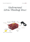
Figure 23: Track Interface.
25
Telemetry Box Rev 1.0
User manual
Warranty: two years. We retain the right to reject under warranty repairs of Track Interface showing
signs of tampering and/or not accompanied by the repair application (downloadable at www.slot.it )
totally filled in. This product is in accordance with RoHS guidelines. Do not dip it into water.
Completely conceived, thought up and realized by Maurizio Ferrari, Maurizio Gibertoni, Cristian
Anceschi and Stefano Giorgi of Galileo Engineering S.r.l., Via F. Cavallotti, 16 – 42122 Reggio
Emilia, Italy – www.slot.it – [email protected] If it does not work, blame it on us.
Slot.it and Slot.it logo are registered trademarks by Galileo Engineering S.r.l..
We thank you for choosing the Telemetry Box system. Before operating, please read this manual
attentively.
26
Telemetry Box Rev 1.0
User manual
9 Contents of the selling pack
In the selling pack is the following material:
•
•
•
1 Track Interface system;
1 cable to connect a DS chrono to the Track Interface: “DS link cable”;
1 male jack-USB female plug cable to collect the signals given by the Track Interface and
bring them to the Telemetry Box: “Track to Telemetry cable”.
10 General description
The Track Interface is a system having the job to interface the Telemetry Box to the sensors (DS
bridge, dead strip...) which are on the track. In particular, it elaborates the signals given by the
sensors so that they can be read by the Telemetry Box, allowing the latter to carry out the expected
functions, such as: lap time playback and time and telemetry data storage.
Each Track Interface is able to manage the signals coming from two lanes, up to a maximum of two
sensors per lane (e.g. a dead strip and a DS bridge), allowing the user to choose the lap counter
sensor and the sector time sensor.
27
Telemetry Box Rev 1.0
User manual
11 Description of the Track Interface
Figure 24: Track Interface: front view.
Figure 25: Track Interface: back view.
28
Telemetry Box Rev 1.0
User manual
Figure 26: Track Interface: right side view.
With reference to the previous pictures, the following components can be distinguished:
1. “Bridge out” DIN plug: where a possible DS chrono can be connected by means of the "DS
link cable";
2. “Power” LED: it signals the presence of power supply;
3. “Lane 1” LED: it signals that the car in lane 1 has passed over a sensor. In particular:
•
one flashing: the car has passed over a sector sensor;
•
two flashing: the car has passed over a lap sensor;
4. “Lane 2” LED: it signals that the car in lane 2 has passed over a sensor. In particular:
•
one flashing: the car has passed over a sector sensor;
•
two flashing: the car has passed over a lap sensor;
5. double switch: it allows to choose the role of the sensors: lap sensor or sector sensor;
6. “External supply” power supply plug: female jack where to connect a 12V transformer,
with capacity at least 1A;
7. “Lane 1” female jack: female jack plug where to insert the male jack plug of the "Track to
Telemetry cable", in order to collect the signals given by the Track Interface concerning the
car in Lane 1;
8. “Lane 2” female jack: female jack plug where to insert the male jack plug of the "Track to
Telemetry cable", in order to collect the signals given by the Track Interface concerning the
car in Lane 2;
9. Dead Strips clamps: where to connect the cables bringing the signal from dead strips to the
Track Interface;
10. Ext. Supply clamps: where to connect the external power supply, taken from the track or
from a power unit;
11. “Bridge in” DIN connector: where to connect a possible DS bridge.
29
Telemetry Box Rev 1.0
User manual
12 Track Interface power supply
The Track Interface can only be powered in one of the following ways:
1. by means of a DS chrono connected with socket (1);
2. by means of an external 12 V DC transformer (at least 1A) connected to female jack (6);
3. by means of an external power supply, whose source can be a bench power supply
connected to the terminal block (10). It must supply a voltage of 12V DC;
4. by combining the previous options.
Once the Track Interface is powered, the LED (2) throws a steady red light and the possible DS
bridge connected to the DIN connector (11) is powered, too.
In case that the track has got more than four lanes, it is advisable to supply all the Track Interfaces
by means of an external power unit connected to the clamps marked by the writing "Ext Supply".
13 Track Interface connections
The Track Interface can be connected to various devices and/or peripheral sensors. These are:
•
DS bridge sensor;
•
DS chrono;
•
dead strip sensor;
•
normally open switch;
•
Wincrono sensor [*];
•
Slot.it SCP-01 controller;
•
Slot.it Telemetry Box.
The sensors (lap and sector) must be positioned on the track at a time space of about six tenths of a
second.
[*] The Wincrono sensor requires a welding on the external shell of the female plug of the relative
wiring. Refer to the relative file with the instructions, downloadable from the website www.slot.it
13.1
Connection to a DS bridge
The Track Interface can be connected to a DS bridge. You only have to insert the DIN male plug of
the DS bridge's cable into the female plug (11), named "Bridge In", of the Track Interface. Once the
Track Interface is powered, the connected DS bridge is powered, too. Notice that the positioning of
the DS bridge on the track affects the correspondence between the LED (3) and (4) of the Track
Interface and the lanes, since the bridge itself decides the numbering order of the lanes.
13.2
Connection to a DS chrono
In order to connect a DS chrono to the Track Interface, the "DS link cable" DIN cable, included in
the package, must be used. You only have to insert the male plug at one and of the cable into the
"Bridge Out"(1) female DIN connector of the Track Interface, whereas the other male plug must be
inserted into the "SENSOR" female DIN connector of the DS chrono. This connection will allow
30
Telemetry Box Rev 1.0
User manual
the driver to see on the display of the DS chrono the times obtained by the DS bridge. Moreover, if
the DS bridge has been chosen as lap counter sensor (see procedure at paragraph 14.1 ), the same
displayed times will be reproduced in the earphones, if a Telemetry Box has been connected to the
Track Interface.
13.3
Connection to a dead strip
The dead strip is a small piece of metal strip of the lane which has been electrically disconnected
from the rest. (See the following picture).
Figure 27: example of dead strips.
In order to pick up the signal from these strips, you only have to weld the end of an electric cable
into the part underlying the strip itself, whereas the opposite end must be inserted into the Dead
Strips clamps (9). This operation must be carried out for each dead strip. In order to obtain
consistency between the times recorded by the DS bridge and by the dead strips, the cables coming
from the dead strip of lane 1 are to be inserted into the clamps marked by number 1 in the Dead
Strip terminal block, those of lane 2 into the clamps marked with number 2. As to the polarity of
the signals, the cables can be reversed trouble-free.
31
Telemetry Box Rev 1.0
User manual
Figure 28: example of the connection of the Track Interface to a dead
strip.
13.4
Connection to Slot.it SCP-01 controller
Figure 29: connection of the Track Interface to SCP controller.
In order to connect the Track Interface directly to a Slot.it SCP-01 controller, you need to use the
"Track to Telemetry cable" of the Track Interface, included in the pack, and the "Connection cable"
of the Telemetry Box, included in the pack of the latter. Firstly, you have to weld the latter cable to
the cartridge of the SCP-01 controller (for doing this, refer to the manual of the Telemetry Box,
paragraph 5.3). Then you only have to insert the male jack plug of the "Track to Telemetry cable" of
the Track Interface into the female jack plug (7) or (8), according as the car is positioned on the first
32
Telemetry Box Rev 1.0
User manual
or the second lane. Then, for the connection to be complete, insert the male plug of the "Connection
cable" of the SCP-01 controller into the USB female plug of the "Track to Telemetry cable" of the
Track Interface. The final result is shown in figure 29.
13.5
Connection to the Slot.it Telemetry Box
In order to connect the Track Interface to the Slot.it Telemetry Box, you only need to use the "Track
to Telemetry cable" of the Track Interface, which can be found in the pack. You only need to insert
the male jack plug of the latter into the female jack plug (7) or (8) according as the car is positioned
on the first or the second lane. Then, for the connection to be complete, you only have to insert the
male plug of the USB white cable(10) of the Telemetry Box into the USB female plug of the "Track
to Telemetry cable" of the Track Interface. The final result is shown in figure 30. Once the Track
Interface is powered, the Telemetry Box is powered, too. The user can check it by making sure that
the LED (5) of the Telemetry Box throws a red light.
Figure 30: connection of the Track Interface to the Telemetry Box.
13.6
Connection to other Track Interfaces
Until now we have seen that a single Track Interface is able to manage only two sensors on the
same lane. What is to be done if the user wishes to use more than one sector sensor? It is necessary
to take another Track Interface and the "Sector Time Expansion Cable" (sold separately) and follow
this procedure:
1. Set the new Track Interface so that it manages the two additional sensors as sector sensors
(see how to do it in paragraph 14.3 );
2. insert one of the male jack plugs of the Expansion Cable into the female jack plug (7) or (8)
of the Track Interface, according as the car is positioned on the first or the second lane;
3. insert the remaining male jack plug of the Expansion Cable into the same female jack plug
33
Telemetry Box Rev 1.0
User manual
of the other Track Interface;
4. insert the male jack plug of the "Track to Telemetry cable" of the Track Interface into the
free female jack plug of the Expansion Cable;
5. according to the type of connection which has to be done (to Telemetry Box or to SCP-01
controller) insert the USB male plug of the "Connection Cable" or of the USB white
cable(10) of the Telemetry Box into the USB female plug of the "Track to Telemetry cable"
of the Track Interface;
6. in case that one wants to add further sector sensors on the track, insert one of the male jack
plugs of the new expansion cable into the female jack plug of the previous expansion cable,
whereas the remaining male jack must be inserted into the female jack plug (7) or (8) of the
new Track Interface, according as the car is positioned on the first or the second lane;
7. then carry out step 5.
Figure 31: connection of various Track Interfaces to each other.
14 Track Interface setting
The Track Interface allows the user to decide what role to give to the sensors, managed by the
Track Interface, thanks to the double switch (5). In particular, with reference to the DS bridge
sensors and dead strip sensors, the following combinations can be obtained:
• DS bridge lap sensor, dead strip sector sensor;
•
DS bridge sector sensor, dead strip lap sensor;
•
DS bridge sector sensor, dead strip sector sensor;
Here it is explained how to position the two switches (5) in order get the above listed combinations.
34
Telemetry Box Rev 1.0
14.1
User manual
Setting: DS bridge lap counter sensor, dead strip sector sensor
In order that the Track Interface interprets the DS bridge as lap counter sensor and the dead strip as
sector sensor, the double switch (5) must be set as shown in figure 32.
Figure 32: Ds bridge lap
count sensor, dead strip
sector sensor.
14.2
In particular, the Bridge switch must be positioned in position 1, the
Dead strips one in position 0. When the car passes under the bridge,
the LED (3) or (4) (according to the lane the car finds itself in) flashes
twice, whereas when the car passes on the dead strip the same LED
flashes once.
Setting: DS bridge sector sensor, dead strip lap counter sector
In order that the Track Interface interprets the DS bridge as sector sensor and the dead strip as lap
counter sensor, the double switch (5) must be set as shown in figure 33.
In particular, the Bridge switch must be positioned in position 0, the
Dead strips one in position 1. When the car passes under the bridge,
the LED (3) or (4) (according to the lane the car finds itself in) flashes
once, whereas when it passes on the dead strip the same LED flashes
twice.
Figure 33: Ds bridge sector
sensor, dead strip lap counter
sensor.
14.3
Setting: DS bridge sector sensor, dead strip sector sensor
In order that the Track Interface interprets both DS bridge and dead strip as sector sensors, the
double switch (5) must be set as shown in figure 34.
In particular, both switches must be positioned in position 0. When the
car passes under the bridge, the LED (3) or (4) (according to the lane
the car finds itself in) flashes once, and the same thing happens when
it passes on the dead strip.
Figure 34: DS bridge sector
sensor, dead strip sector
sensor.
35
Telemetry Box Rev 1.0
14.4
User manual
Not allowed Setting
Figure 35: not allowed setting
In figure 35 the last possible switch combination for sensor setting is
shown. This combination would tell the Track Interface to consider
both DS bridge and dead strip as lap counter sensors, but this is
impossible. The Track Interface signals this wrong combination by
making LED (3) and (4) flash until the user changes the setting.
Moreover, during this situation the Track Interface does not carry out
any function.
36
Telemetry Box Rev 1.0
User manual
Notes
CE mark
residential
This device is compliant with the requirements of the CE mark for uses in
districts, shopping precincts, vehicular and light industrial zones.
RAEE / WEEE directive
This symbol on the product or on the package indicates that this
product must be separated from household-type waste.
In conformity with 2002/96/EC European directive on waste electrical
and electronic equipment (RAEE /WEEE), this electrical product
cannot be disposed of together with undifferentiated waste. This
product must be disposed of by means of restitution to the dealer or to
the local waste collection area for recycling.
37
Telemetry Box Rev 1.0
User manual
38
Telemetry Box Rev 1.0
User manual
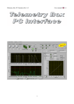
The software Telemetry Box PC Interface is a graphic interface that allows the user to carry out
some operations, which can be divided in three groups:
•
operations on the Telemetry Box connected to the PC (e.g. language download or telemetry
data download etc.);
•
postprocessing operations on the data downloaded by the Telemetry Box or saved during the
live telemetry function;
•
live telemetry operation and/or PC chronometer: both, if in possession of the SCP controller;
PC chronometer only, if in possession of another type of controller
In order to be able to use the interface, the following software packages must be downloaded:
•
TelBoxPCIntRunTime: it must be installed on the PC in order that the PC is able to run the
Telemetry Box PC Interface application;
•
TelemetryBoxPCInterface: it is the actual application that must be launched with a double
click of the mouse's left key on the representative icon.
N.B. The present version of Telemetry Box PC Interface can be run only on PCs with Windows 7 or
XP operating system. Windows Vista is not supported, not will it be officially, even if it might
work.
39
Telemetry Box Rev 1.0
User manual
15 Installation of TelBoxPCIntRunTime
Once the file TelBoxPCIntRunTime.zip has been downloaded, it is necessary to decompress it and to
run, with a double click, the file setup.exe which can be found in the "Volume" directory. The
installation of the runtime begins. During this phase a series of windows will appear; here they are
listed in order of appearance, with their meaning and the operations to be followed for each
window:
1. destination directory: it asks to specify the directory where to install the Telemetry Box PC
Interface application and the relative products. We suggest not to change the proposed
settings and push "Next";
2. requested license agreement: choose "I accept the License Agreement" and push "Next";
3. repeat the operation of step 2);
4. summary of the software that will be installed: the list of what is going to be installed; push
"Next". Now the installation begins, its progress is shown in the following window;
5. end of installation: push "Finish". Then the last window appears: push "Restart" in order to
restart the PC as required.
Once the PC has been restarted, it is possible to move on to the use of Telemetry Box PC Interface
application, with a double click of the mouse's left key on the icon of the application itself.
16 Use of the Telemetry Box PC Interface application
16.1
Driver installation
When connecting the Telemetry Box to the PC for the first time, through a generic USB cable (type
AB), Windows requires the installation of the driver necessary for the communication between the
Telemetry Box PC Interface application and the Telemetry Box itself. The name of the driver is
TelemetryDriver.inf and it is in the package containing the Telemetry Box PC Interface application.
Here are the operations to carry out for each window that appears during the operation:
1. chosen the third option, “No, not now”, and push “Next”;
2. choose the second option: "Install from a list or specific location(advanced)" and push
"Next";
3. choose the last option: manual choice of the driver to be installed, then push "Next";
4. by pushing "Driver Disk", choose the driver to be installed (TelemetryDriver.inf), then push
"Next";
5. push "Continue": the driver installation starts;
6. when the end of installation window appears, push "Finish";
7. now a second installation begins: carry out all the above listed operations again;
8. in order to verify that the installation has been successful, go into the "Device manager" of
the PC and verify that, with the Telemetry Box connected to the PC, the devices shown in
figure 36 appear.
40
Telemetry Box Rev 1.0
User manual
Figure 36: Telemetry box PC Interface driver installation's result check.
16.2 Use of the Telemetry Box PC Interface application to
communicate with the Telemetry Box
In order to run the application Telemetry Box PC Interface you only have to position the mouse's
indicator on the icon of the application itself and make a double click with the left key. The
Telemetry Box PC Interface can present itself in two different ways according that the Telemetry
Box is connected or not to the PC. If the Telemetry Box is not connected to the PC, the application
presents itself as shown in figure 37, otherwise as shown in figure 38.
41
Telemetry Box Rev 1.0
User manual
Figure 37: starting windows Telemetry Box PC Interface with disconnected Telemetry Box.
Figure 38: starting windows Telemetry Box PC Interface with connected Telemetry Box.
42
Telemetry Box Rev 1.0
User manual
In case of disconnected Telemetry Box (figure 37), the user can carry out one of the following
operations, as summarized by the message on the monitor:
•
•
•
connect the Telemetry Box to the PC by means of a USB cable for printer (type AB) and
push "OK". This means that the situation is now the one described in figure 38: use of the
Telemetry Box PC Interface application to communicate with the Telemetry Box (see
paragraph 16.2.1 );
push "POST" in order to go to the Postprocessing phase;
push "QUIT" in order to stop the running of the Telemetry Box PC Interface application.
In case of connected Telemetry Box (figure 38), it can be observed that on the right side of the page
there is a series of data, the result of a first data exchange between the Telemetry Box PC Interface
application and the Telemetry Box. These are:
1. the software version of the Telemetry Box PC Interface application which is being run;
2. the software version of the Telemetry Box connected to the PC;
3. the language of lap times playback in the driver's earphones on the internal memory of the
Telemetry Box;
4. the status of the connection of the Telemetry Box. In particular, next to the writing
"Connection" one of the following sentences can appear:
• "no box": no Telemetry Box is connected to the PC (the situation is the one of figure
37);
• "telemetry box": the Telemetry Box is connected to the PC by means of a USB cable
for printer (type AB) and nothing else is connected to the Telemetry Box by means of
the white USB cable;
• "telemetry box + SCP controller": the Telemetry Box is connected to the PC and to a
SCP controller;
• "telemetry box + Track Interface": the Telemetry Box is connected to the PC and to a
Track Interface.;
5. the number of sectors indicated by the user for carrying out the live Telemetry.
On the left side of the same page (figure 38) is a drop-down menu, "Selected function", in which all
the functions that can be carried out are listed, but the enabled ones are only the ones that can be
carried out on the basis of what the Telemetry Box is connected to in this moment. For example: if
the Telemetry Box is connected to the PC only, the "telemetry" function is not enabled since it
requires that the Telemetry Box is connected to a SCP controller, too.
16.2.1
Use the application to communicate with the Telemetry Box
In case that the Telemetry Box is connected to the PC only, the user can decide the operation he
wants to carry out among the enabled ones, by means of the "Selected function" drop-down menu
(figure 39). In particular, in this configuration, one of the following functions can be selected:
1. “Postprocessing”: it allows to analyse the data saved on the PC during the Telemetry Live
function or downloaded from the Telemetry Box and then saved on the PC. For further
details, see paragraph .
2. “Download language”: it allows to update/change the language of lap time playback. For
43
Telemetry Box Rev 1.0
User manual
further details, see paragraph .
3. “Download telemetry data”: it allows to download and save in a file the data stored on the
internal memory of the Telemetry Box. For further details, see paragraph .
4. “Erase stored data”: it allows to erase the data stored on the memory of the Telemetry Box.
For further details, see paragraph .
Figure 39: Selected function menu.
In case that the Telemetry Box is connected at the same time to the PC and to a SCP controller or to
a Track Interface, the following functions from the "Selected function" menu are enabled:
1. “Telemetry”: it allows to enter the "Live Telemetry" function and/or the "PC chronometer"
function, according to what the Telemetry Box is connected to, by means of the white USB
cable. In particular:
1.1. Telemetry Box connected to the PC and to the Track Interface: it is possible to enter
the "PC chronometer" function only. This is valid for firmware versions of the Telemetry
Box from 1.0.3. For the previous versions, the enabled functions are the same that are
enabled in the situation of Telemetry Box connected to the PC only;
1.2. Telemetry Box connected to the PC and to the SCP controller: it is possible to enter
both the "live Telemetry" and the "PC chronometer" functions;
2. “Postprocessing”: it allows to analyse the data saved on the PC during the live Telemetry
function or downloaded from the Telemetry Box and then saved on the PC. For further
details, see paragraph .
44
Telemetry Box Rev 1.0
User manual
Download Language function
In order to change or update the language of lap times playback it is necessary to select the
"Download Language" function. This involves the appearance of a message signalling to the user
that the operation causes the erasure of all the data from the internal memory of the Telemetry Box.
Pushing:
• “yes”: a window appears in which to select the language one wishes to download: for
example, ItalianLanguage.txt. In case that the Telemetry Box contains a language different
from the selected one, the setting of the memory begins immediately, otherwise a message
appears asking to the user if he wishes to overwrite it. If not, one returns to the "Function
Selection" page, alternatively the download phase begins, during which the "Audio Off" red
LED of the Telemetry Box is on. The end of the operation is signalled by the application
with a message in which it is necessary to push "OK". Once the operation is completed, the
application returns to the initial page, "Function selection";
• “no”: one returns to the initial page, “Function selection”.
Returning to the initial page, "Function selection", a message reminds the user that, in order to
move on to other operations, it is necessary to select one of them from the "Selected function" dropdown menu.
Download telemetry data function
In order to download the data stored on the internal memory of the Telemetry Box, the user must
select "Download telemetry data" from the "Selected function" drop-down menu. Once this function
has been selected, a window appears asking to specify the name of the file in which to save the data.
According to the inserted name, the following situations can arise:
•
•
already existing file having the same name: a message appears asking the user if he wants
to overwrite the file. If he does not, he is asked to insert a new name, otherwise the
download phase begins;
non-existent file: the download phase begins immediately.
During the download, the application creates two files both having the name indicated by the user,
but differentiated by the addition, at the end of the name, of "_t" and "_d" (for example, if the name
is Dati.txt, the created files will be Dati_t.txt and Dati_d.txt). The file ending with "_t" contains the
times of the driver, the other file the possible telemetry data. If there are no telemetry data, the latter
file is created anyhow, but it remains empty. In case that the two files are already present, the
application asks permission to overwrite them: if the permission is given, the download phase
begins, otherwise the user is asked if he wants to create a new file, in order to save the data, or if he
prefers to annul the download operation. If he decides to annul the operation, the application returns
to the initial page, "Function selection", otherwise the download phase begins. At the end of this,
the application asks the user if he wants to move directly on to the postprocessing phase. If yes, the
relative pages appear (see figure 42 and 43), otherwise the initial page "Function selection"
reappears, where a message reminds the user that in order to move on to other operations, it is
necessary to select one of them from the "Selected function" drop-down menu.
Note that for the entire duration of the download the "Audio Off" LED throws a steady red light.
45
Telemetry Box Rev 1.0
User manual
Erase stored data function
In order to erase the data stored on the internal memory of the Telemetry Box it is necessary to select
"Erase stored data" from the "Selected function" drop-down menu. Once this function has been
selected, a message appears reminding the user that the data stored on the internal memory of the
Telemetry Box are going to be erased. Note that only the stored data are going to be erased, the
language is not. Pushing "YES" the two following situations can arise:
•
the internal memory of the Telemetry Box is empty: this signalled by a proper message.
Pushing "OK", one returns to the initial page, "Function selection";
•
the internal memory of the Telemetry Box is not empty: the erasure begins. During the
operation the "Power/Mem" LED of the Telemetry Box flashes with red light. At the end of
the operation, signalled by the application with a message, one returns to the initial window,
"Function selection".
Returning to the initial page, "Function selection", a message reminds the user that, in order to
move on to other operations, it is necessary to select one of them from the "Selected function" dropdown menu.
Telemetry function
In case that the user selects the "Telemetry" function, he is asked by the Telemetry Box PC Interface
application to carry out the following operations before the function can begin:
•
insert the number of sectors the track is made up of;
•
push the "START TEL" button, that is flashing with yellow light;
•
insert the name of the file in which the data have to be saved, with also the file extension
.txt. The application creates two different files with this name, differentiated by the
addition, at the end of the name, of "_t" and "_d" (for example, if the name is Dati.txt, the
created files will be Dati_t.txt and Dati_d.txt). In the former the driver's times are saved, in
the latter the telemetry data, in case that a SCP controller is being used. In case that the two
files are already present, the application asks permission to overwrite them: if the
permission is given, the telemetry phase begins, otherwise the user is asked to indicate a
new name in order to save the data.
Now the "Telemetry" function is being carried out. According to the device the Telemetry Box is
connected to, the following situations can arise:
• Telemetry Box connected to the PC and to the Track Interface: a single page appears:
"Telemetry". Note: the use of the "Telemetry" function with Telemetry Box connected to the
PC and to the Track Interface is only possible from the firmware version 1.0.3 of the
Telemetry Box;
• Telemetry Box connected to the PC and to the SCP controller: (in this case the SCP
controller is connected to the Track Interface): two pages appear: “Telemetry” and "PC
chrono".
The "Telemetry" page shows the following data (see figure 40):
• brake performance;
• minimum and maximum speed set by the user and real-time performance of the applied
46
Telemetry Box Rev 1.0
User manual
speed in conformity with the chosen anti-spin value;
• regulation curve set by the user on the SCP controller;
• real-time status of the knobs and switches of the SCP controller;
• lap time and lap number;
• best lap time and its number;
• firmware version of the SCP controller and Telemetry Box in use; the type of cartridge
connected to the controller; language of the Telemetry Box.
Figure 40: Telemetry page.
The "PC chrono" page shows the following data (see figure 41):
• lap time and lap number;
• best lap time and its number;
• list of the last ten laps with relative time.
47
Telemetry Box Rev 1.0
User manual
Figure 41: PC Chrono page.
Here is a brief description of the function of the various buttons that can be found in the "Telemetry"
page (figure 40):
• Reset all: it erases the data displayed in the following fields: Lap time, Lap number,
Sector time, Sector number, Best time and Best lap;
• Reset best time: it erases the best time recorded until that moment and the corresponding
lap number;
• STOP TELEMETRY: by pushing this button, the user is asked if he wants to move on
directly to the postprocessing function. If yes, the postprocessing phase begins (for its
description, see paragraph ), otherwise the Telemetry Box PC Interface application returns
to the starting page (figure 38) "Function selection", where a message reminds the user
that, in order to move on to other operations, it is necessary to select one of them from the
"Selected function" drop-down menu.
Postprocessing function
By selecting the "Postprocessing" function, the page shown in figure 42 appears. It is divided in
two sections, DRIVER1 and DRIVER2. It is possible to load the data of two different drivers or of
two different runs of the same driver in order to compare them. In order to continue, it is necessary
to select the file to be analysed, using the Browse "Path_file1" and/or "Path_file2" button. Among
the available files it is necessary to choose the one ending with "_t.txt". Once the selection has been
done, the relative times are reported in the table to the side. The worst time is highlighted in red, the
best time in green. Moreover, if telemetry data are present, too, the Telemetry Box PC Interface
application enables a second page, "Postprocessing 2" (figure 43), in which the telemetry data can
48
Telemetry Box Rev 1.0
User manual
be visualized, by selecting the intended lap number.
Figure 42: postprocessing page.
With reference to the "Postprocessing" page (figure 42), here is the meaning of each button:
•
•
•
•
•
CLEAR TABLE: it erases the just loaded table and file;
REFRESH TABLE: it updates the loaded table;
PRINT TABLE: pushing this button a new window appears that allows to set the font, the
colour, the size, and the number of copies to be printed;
DELETE FILE: it erases the loaded file permanently;
STOP POSTPROCESSING: it provokes the stop of the "Postprocessing" function; the
Telemetry Box PC Interface application returns to the starting page, "Function selection"
(figure 38), where a message reminds the user that, in order to move on to other operations,
it is necessary to select one of them from the "Selected function" drop-down menu.
It is also possible to sort the data reported by one of the column of the table by clicking on the
table's heading.
49
Telemetry Box Rev 1.0
User manual
Figure 43: postprocessing 2.
As shown in figure 43, the buttons can be divided in three groups: DRIVER 1, DRIVER 2 and
COMPARE. These are not enabled at the same time, but only as follows:
•
•
•
those belonging to the first group, DRIVER 1, are enabled only if the user loads the data in
the DRIVER 1 section of the "Postprocessing" page, that is, using the browse "Path_file1"
button;
those belonging to the second group, DRIVER 2, are enabled only if the user loads the data
in the DRIVER 2 section of the "Postprocessing" page, that is, using the browse
"Path_file2" button;
those belonging to the third group, COMPARE, are enabled only if the user loads the data in
both DRIVER 1 and DRIVER 2 sections of the "Postprocessing" page. This is the case of
the comparison of, for example, the data of two different drivers;
In the "Postprocessing2" page (figure 43), the following data can be seen:
•
•
brake performance;
minimum and maximum speed set by the user and real-time performance of the applied
speed in conformity with the chosen anti-spin value;
Here is a description of each button of the "Postprocessing2" page:
•
DRAW GRAPH: it allows to see the above listed data concerning the selected lap. In
particular, the brake value is displayed in the "BRA" graph, the other values in the "OTH"
graph. If no lap number has been selected, a message informs the user that, in order to
continue, it is necessary to specify the lap number to be visualized. The selected lap number
50
Telemetry Box Rev 1.0
User manual
is also displayed in the "Selected 1st lap #" field;
•
ADD NEW LAP: it allows to select a further lap, so that it is possible to compare the data
concerning the two selected laps. The number of the additional selected lap can be seen in
the "Selected 2nd lap #" field. In order to go on to visualize the data, push the "DRAW
GRAPH" button again;
•
REMOVE LAP: it allows to select the lap number to be removed, among the already
selected ones;
•
CHANGE LAP #: it allows to indicate the lap number to be visualized and, in case that two
laps have already been selected, it allows to change the last selected one;
•
DRAW ALL GRAPHS: it allows to visualize the data concerning the selected lap for both
drivers at the same time;
•
CHANGE LAP# ( COMPARE group): it allows to indicate the number of laps, one for each
driver, that one wishes to compare. In particular, pushing the button, a new window appears
where it is necessary to act as follows:
•
select the number of the driver one wishes to select the lap of;
•
indicate the lap number;
•
select the number of the second driver one wishes to select the lap of (optional, since it
is possible to change the lap number of one driver only);
•
indicate lap number;
•
push “OK”;
•
TRACES STATUS: it allows to choose which data will be kept displayed on the two graphs:
if the green light is on, the datum is displayed, otherwise it is hidden;
•
CLEAR GRAPH: it allows to erase the values one has just visualized. Note: by pushing the
button, the above standing graph is cleared, but the values are not erased from the memory:
they can be visualized again by pushing "REDRAW GRAPH";
•
REDRAW GRAPH: it allows to draw the above standing graph again;
•
ZOOM: it allows to zoom in on the above standing graph;
•
STOP POSTPROCESSING: the Telemetry Box PC Interface application returns to the
starting page, "Function selection" (figure 38), where a message reminds the user that, in
order to move on to other operations, it is necessary to select one of them from the "Selected
function" drop-down menu.
51