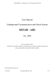
1
User’s manual
ESS III
data logger
Btr. ESS III
Indications for explosion proof instruments
Union Apparatebau GmbH
P.B. 21 10 51
D – 76185 Karlsruhe
Zeppelinstrasse 42
D 76160 Karlsruhe, Germany
Phone +49 721 – 95243 – 0
Fax
+49 721 – 95243 – 33
e-mail [email protected]
www.union-apparatebau.de
2
Btr ESS III english 07-04-05 gelb.doc
Indications for explosion proof instruments
Btr. ESS III
Table of contents
1.
2.
3.
4.
4.1.
4.2.
4.2.1.
5.
5.1.
5.2.
5.3.
5.3.1.
5.4.
5.5.
5.5.1.
5.5.2.
5.5.3.
5.5.4.
5.5.5.
5.5.6.
5.5.7.
5.5.8.
5.5.9.
5.5.10.
5.6.
5.6.1.
5.6.2.
5.6.2.1.
5.6.2.2.
5.6.2.3.
5.6.2.4.
5.6.2.5.
5.6.2.6.
5.6.2.7.
5.6.2.8.
5.6.2.9.
5.6.3.
5.6.3.1.
5.6.3.2.
5.6.3.3.
5.6.3.4.
5.6.4.
Indications for explosion proof instruments .......................... 6
Technical data ESS III System............................................. 7
Introduction........................................................................... 8
First time putting into operation ............................................ 9
Installation of the connection................................................ 9
Working with TfsWin III ...................................................... 11
Transfer to the computer .................................................... 12
Handling the ESS III ........................................................... 13
Overview ESS III gas ......................................................... 13
Overview ESS III water ...................................................... 14
Overview ESS III temperature............................................ 15
ESS III temperature with different sensors......................... 16
Overview ESS pressure and temperature.......................... 17
ESS III display indications .................................................. 18
Menu mode ........................................................................ 18
Measuring rate indication ................................................... 18
Battery indication................................................................ 18
Action bar ........................................................................... 19
Numeric display field .......................................................... 19
Storage mode..................................................................... 19
Storage on-off..................................................................... 19
Menu display field............................................................... 19
Remaining memory ............................................................ 19
Units ................................................................................... 19
Measuring with the ESS III ................................................. 20
Main menu.......................................................................... 20
Menü INFO - Information.................................................... 21
RANL/RANH - Range low/high........................................... 22
MEM (Memory) - Total memory ......................................... 22
RMEM - Remaining memory .............................................. 22
SNOD - Serial no. evaluation unit) ..................................... 22
SNOS - Serial no of sensor ................................................ 22
CALI- -Calibration date....................................................... 22
DATE - Date ....................................................................... 22
TIME - Time........................................................................ 22
VERS - Version .................................................................. 22
Menu PMTR - Parameters ................................................. 23
CHNL - Channel ................................................................. 23
SMPR - Sample rate .......................................................... 23
CLCK - Clock...................................................................... 23
PASS (Password) – Password........................................... 23
Menu COMM - Commands ................................................ 23
Btr ESS III english 07-04-05 gelb.doc
3
Btr. ESS III
5.6.4.1.
5.6.4.2.
5.6.5.
6.
6.1.
6.2.
6.3.
6.4.
6.5.
6.5.1.
6.5.2.
6.6.
6.7.
6.8.
6.9.
6.10.
6.11.
6.12.
7.
7.1.
7.2.
7.3.
7.4.
7.4.1.
7.4.2.
7.4.3.
7.4.4.
7.4.5.
7.4.6.
7.4.7.
7.5.
7.6.
8.
8.1.
8.2.
8.3.
8.4.
8.5.
8.5.1.
8.5.2.
9.
9.1.
9.2.
4
Indications for explosion proof instruments
DEL - Delete....................................................................... 23
PWSV - Powersave............................................................ 24
All abbreviations in the menus ........................................... 25
Working method of the ESS III-System.............................. 29
Storing measuring values................................................... 30
Target limits........................................................................ 30
Alarm limits......................................................................... 30
Resolution .......................................................................... 30
Measuring rate and battery life time ................................... 30
Measuring rate ................................................................... 30
Battery life time.................................................................. 31
Measuring average factor................................................... 31
Storage of min-max-values ................................................ 31
DIF Value ........................................................................... 31
Time ................................................................................... 31
Remaining memory ............................................................ 31
Resolution of the measuring value ..................................... 32
Zero point correction .......................................................... 32
TfsWin III ............................................................................ 33
Installation of the program.................................................. 33
Installation of the IrDA-interface cable ............................... 34
Functions of TfsWin III ....................................................... 34
Menus................................................................................. 36
File...................................................................................... 36
Edit ..................................................................................... 36
ESS .................................................................................... 37
Display................................................................................ 39
Macro ................................................................................. 40
Options ............................................................................... 41
Help .................................................................................... 42
Function buttons................................................................. 43
Parameter list ..................................................................... 45
Maintenance....................................................................... 47
Battery block....................................................................... 47
Inserting the batteries......................................................... 47
Waterproofness of the housing .......................................... 48
IR-transmission .................................................................. 48
Exchanging sensors ........................................................... 48
ESS III for water ................................................................. 48
ESS III for gas .................................................................... 49
Error diagnostic .................................................................. 50
Display is weak or blind...................................................... 50
Moisture on the display ...................................................... 50
Btr ESS III english 07-04-05 gelb.doc
Indications for explosion proof instruments
9.3.
10.
10.1.
10.2.
10.3.
10.4.
10.5.
11.
12.
13.
Btr. ESS III
Transmission was interrupted ............................................ 50
Measuring sensors ............................................................. 51
Barometer sensor............................................................... 51
Overpressure protection..................................................... 51
Pressure monitoring in water pipe networks ...................... 51
Accessories, equipment, spare parts ................................. 53
Transport cases.................................................................. 53
Spare part list ..................................................................... 54
EU-Declaration of conformity ............................................. 55
EU-Design test certificate................................................... 56
Btr ESS III english 07-04-05 gelb.doc
5
Btr. ESS III
1.
Indications for explosion proof instruments
Indications for explosion proof instruments
• Application area and prescriptions
These indications and warnings must be considered absolute to
guarantee an employment without danger. The devices may only
be employed for the intended application. Employment is allowed
in areas that are potentially explosive by gases or vapours. They
are assigned to the explosion group and temperature class,
indicated on the type plate. With the establishment and the
exploitation of explosion protected control- and measuring-installations, the
applicable national regulations and prescriptions have to be considered.
• General indications
For safe exploitation of the device, professional transport,
appropriate storing and assembly as well as careful operation
and maintenance, is necessary. Any intervention at the device
must be carried out by authorized personal, exclusively using
original spare parts. The electrical data, stated on the type plate
and the test certificate as well as their special conditions have to
be considered.
When operated in the open air, it is advised to protect the explosion protected
devices against direct water influences.
• Assembly and maintenance
Before assembling, it must be checked, if the indication on the
type plate coronds with the required kind of protection for the
potentially explosive area. At battery exchange, only an original
battery block of the manufacturer with Ex. Protection approval
and Ex-characteristic on the packing and the battery block may
be used.
6
Btr ESS III english 07-04-05 gelb.doc
Technical data ESS III System
2.
Btr. ESS III
Technical data ESS III System
Measuring range pressure gas:
0…
0…
0…
0…
0…
0…
0…
100
250
1
2, 5
10
25
100
mbar r
mbar r
bar r
bar r
bar r
bar o
bar o
r gage pressure
r gage pressure
r gage pressure
r gage pressure
r gage pressure
absolute pressure
absolute pressure
Measuring range pressure water:
0… 10
0… 25
bar o
bar o
absolute pressure
absolute pressure
Measuring range temperature:
-10…+40 °C
-20…+60 °C
0…+150 °C
Other measuring ranges on request
Overpressure protection:
Connection:
Accuracy:
Resolution:
Memory:
Power supply:
Power consumption:
Battery operating time:
Protection:
Ex-proof protection:
Seal material:
Dimensions:
Weight:
Operation temp.:
Storage temp:
up to 1,3-times the end of the range
½“ male thread with 1/8“ female thread
± 0,4 % of measuring range end val. (optional 0,2 % or
0,1%)
less than ± 0,01 % full scale
250 000 measuring values
2 Lithium cells (2 x 3,6V / 7,2Ah)
Power save: ca. 45uA, active: ca. 20mA
ca. 5 years at measuring rate 1 minute
IP 54 at ESS type gas (IP 65 at range >10 bar)
IP 68 at ESS type water
II 2 G EEx ib IIC T4
NBR70 or Viton
ca. 108 x 161 x 77 mm (W x H x D)
1200 g
-20 ... +60°C
-20 ... +60°C
IrDA-interface cable serial:
Connection:
9-pin D-SUB-Bus
IrDA-interface cable USB:
Connection:
4-pin USB-connector
Btr ESS III english 07-04-05 gelb.doc
7
Btr. ESS III
3.
Introduction
Introduction
The ESS III - system (electronic memory recorder) is a further development of the
mechanical recorders which have been used for decades in the gas- and water
industry.
The electronics are capable of simulating and storing all relevant data. The system is
independent of power supply and robust built which makes it universal applicable.
There are four instrument building groups all based on the same electronics.
1. ESS III for measuring gas pressure.
There has been given much attention foot high accuracy at lower
measurement ranges, e.g. 100 mbar. At low temperatures e.g. -15 °C,
changes of less than one mbar can be measured very accurate. With special
calibration an accuracy of 0,1% can be achieved over the total temperature
range of -20 to +40°C.
2. ESS III for measuring water pressure.
The instruments are absolutely watertight and can even be water over floated
for several days. The building form is constructed for under floor hydrants. The
absolute pressure is measured.
3. ESS III station recorder
In this instrument 4 measurement values are captured (with sensor-extension
module up to 9 measurement values). All important information in a pressure
reducer station can be recorded. They are an important help for real time
monitoring.
4. ESS III DPK
The pressure test case is a composition of an ESS III with a battery powered
printer. For pressure tests locally at the site, a pressure test can be done and
immediately printed. Out of pressure and temperature, the temperature
compensated pressure is calculated. This is important for the evaluation of the
tightness.
The construction of the ESS III is flexible. The system has a large data memory and
a large program memory. The program memory, which controls the operating
system, can be updated by the customer himself. Older instruments can be updated
with actual software.
The pressure sensors are pre-calibrated in a sensor housing and can be exchanged.
The evaluation unit is identical for all measurement ranges.
Both the evaluation unit and the sensor are explosion proof.
8
Btr ESS III english 07-04-05 gelb.doc
First time putting into operation
4.
Btr. ESS III
First time putting into operation
At delivery the instrument is in the power save mode PWSV. In this mode the power
consumption of the ESS III is very low but it is still active and reacts on input
commands. In this mode the instrument is stored.
By pushing button
“enter“, during the time the action bar is moving, the system
is activated and switches to the measuring mode.
Attention: At releasing the button the function is executed. That applies to all actions
of the ESS III program.
In this mode the other 3 buttons are inactive.
The ESS III measures and stores the pressure. Usually now is measured with the
adjustments set by the manufacturer. These are the adjustments that were active
before switching the ESS in power save mode.
In this mode the instrument can be installed and than measures with the following,
pre-adjusted parameters.
Measuring rate
4 sec
Resolution
0,5 %
Storage mode
standard (static)
Upper target limit
off
Lower target limit
off
Average factor
1
4.1.
Installation of the connection
The ESS III has 2 type plates. At the back of the instrument is a serial number for the
evaluation unit and at the sensor is a serial number for the measuring range. The
customer can change the sensor. Both serial numbers are registered. The pressure
must be within the measuring range. Overpressure up to 1,3-times the measuring
range is allowed. Plausible measurement data are only obtained within the span of 4% to +104% of the range. The measuring range extends at the top to approx.
104%, and at the bottom to approx. 4% below the zero point. As a result the zero
point can be clearly checked.
The ESS III should then via the ½" male thread be screwed onto a measuring point
with internal union nut and may be fitted in any position. Instruments with a
Btr ESS III english 07-04-05 gelb.doc
9
Btr. ESS III
First time putting into operation
measuring range in mbar are position dependent. The zero point should be corrected
in the final measuring position.
ESS for temperature is attached directly to the sensor, using a union nut. The sensor
tip should be placed in the medium either directly or by a dip sleeve. The ESS III
model with a flexible connection to the temperature sensor should be installed in a
fixed position and the sensor placed in the measuring medium.
Barometer ESS III is installed without any connection. The output is than left open.
10
Btr ESS III english 07-04-05 gelb.doc
First time putting into operation
4.2.
Btr. ESS III
Working with TfsWin III
The program TfsWin III reads the measurement data of the ESS III and displays
them. The program is indicating how to install the software. After starting the
program the following display appears:
1
2
3
4
5
Figure 1: TfsWin III start display
1
3
5
Menu bar
List of measurement places
Diagram field
2
4
Icon bar
Channel
1
2
3
Figure 2: TfsWin III enlargement of the start display
Btr ESS III english 07-04-05 gelb.doc
11
Btr. ESS III
First time putting into operation
Example data can be displayed immediately. After marking the map „Channel 1
(Druck)“ in window 2, the parameters are displayed. The diagram (3) is displayed by
marking „Data -11/08/2006 11:51:55“.
Figure 3: TfsWin III display with example curve
The measurement data are now transferred from the ESS III to the PC. The IrDAinterface cable is available with an USB interface or with a serial interface. When
using a serial interface, communication with the ESS III can start immediately. With
the USB cable the installation of a driver has to be confirmed during software
installation.
4.2.1.
Transfer to the computer
After the ESS III has measured for some time, the measurement data can be read.
The IrDA-interface cable is connected to the computer interface (serial or USB) and
the transfer head is connected to the adapter pins at the ESS III. With menu point
ESS / Receive measurement data (all channels) the transfer is started.
After ending the transfer successfully, with a complete occupied memory this can last
about 2 minutes, the curve appears on the screen.
After the first test, in following chapters all functions of the ESS III and TfsWin III will
be explained.
12
Btr ESS III english 07-04-05 gelb.doc
Handling the ESS III
5.
Btr. ESS III
Handling the ESS III
Handling of the separate ESS III for gas, water or temperature are identical. Also
instruments with 2 channels (pressure and temperature) are operated in the same
way. The DPK III (pressure test case) is equipped with an ESS III for pressure and
temperature. The software adapts itself to the pressure test.
5.1.
Overview ESS III gas
Figure 4: ESS III with sensor housing
1
3
5
7
9
Display
4 Operation buttons
Adapter pins
Field for sensor data
G½“ male thread
Btr ESS III english 07-04-05 gelb.doc
2
4
6
8
10
Arrestor ring
IR window ESS III
IR window ESS II
Sensor housing
G1/8“ female thread
13
Btr. ESS III
5.2.
Handling the ESS III
Overview ESS III water
Figure 5 : ESS III water
1
3
5
LCD-display
Sensor housing
Test screw
2
4
6
Connection G½“
Field for sensor serial nr.
Front plate arrestor ring
The ESS III for water pressure is watertight. It can be mounted directly in a hydrant.
For this purpose a bayonet adapter is available which can be tightened with a normal
hydrant-key. Even water over floating of the ESS III is possible for some time.
14
Btr ESS III english 07-04-05 gelb.doc
Handling the ESS III
5.3.
Btr. ESS III
Overview ESS III temperature
Figure 6: ESS III for temperature measurement, fixed sensor
1
3
LCD-display
G¾“ internal union nut
2
4
Field for sensor data
Temperature sensor
There are standard measuring ranges (See page 7). Other measuring ranges can be
ordered for a special price.
Btr ESS III english 07-04-05 gelb.doc
15
Btr. ESS III
5.3.1.
Handling the ESS III
ESS III temperature with different sensors
Figure 7: ESS III for temperature measurement, flexible sensor
Changing sensor type can be done by the manufacturer. The active part of the
sensor is located in a range of some millimetres in the sensor point.
16
Btr ESS III english 07-04-05 gelb.doc
Handling the ESS III
5.4.
Btr. ESS III
Overview ESS pressure and temperature
Figure 8: ESS III with pressure and temperature sensor
1
3
5
7
9
LCD-display
Connection temp. sensor
Sensor housing pressure
Temperature sensor
G½“ male thread
2
4
6
8
Pressure/temp – indication
Connector temp. sensor
Temperature sensor
G3/4" internal union nut
ESS III for pressure and temperature are delivered with the same sensor types as the
standard ESS III. The TfsWin III Software is adapting to the pressure and temperature
measuring range.
Btr ESS III english 07-04-05 gelb.doc
17
Btr. ESS III
5.5.
Handling the ESS III
ESS III display indications
All fields for display indications are described. Several segments show symbols and
numbers in different formats and text.
Figure 9: ESS III display indications
1
3
5
7
9
11
5.5.1.
Menu mode
Battery indication
Numeric indication field
Storage on/off
Memory
Units
2
4
6
8
10
12
Measuring rate indication
Action bar
Storage mode
Menu indication field
Remaining memory
Alarm limits
Menu mode
The symbol
for menu appears only in the different menu modes and not in the
measuring mode.
5.5.2.
Measuring rate indication
The measuring rate indication is blinking in the measuring rate. It changes from
visible to invisible when 1 cycle is ended.
5.5.3.
Battery indication
The battery symbol appears, when the capacity of the battery is at 5%. It mainly
depends on the measuring rate if the instrument can go on functioning for weeks or
even months. See the table in this manual.
18
Btr ESS III english 07-04-05 gelb.doc
Handling the ESS III
5.5.4.
Btr. ESS III
Action bar
The action bar moves from left to right. When the ESS III needs some time for a
certain action, the action bar shows the status. Releasing the button executes the
instruction.
5.5.5.
Numeric display field
In this segment all numeric indications with the corresponding formats are displayed.
The appropriate format, date, number or in special cases even short information, is
switched on with the matching menu point.
5.5.6.
Storage mode
The memory switches from standard (static) storage to rolling storage.
The standard (static) memory is written until completely full. Only after deleting the
old values, new values will be stored.
The rolling
Memory overwrites the oldest values and stores the actual values.
Deleting the memory starts a new measurement.
5.5.7.
Storage on-off
The memory can be switched on or off. With memory switched off measuring
continuous with the actual parameters. Values are not stored.
5.5.8.
Menu display field
In this field all menus are displayed. The abbreviations of all menus are described in
chapter 5.6.5.
5.5.9.
Remaining memory
The remaining memory is indicated in steps of 5%. After the first stored value the
indication switches from 100% to 95%.
5.5.10. Units
In Europe the units mbar, bar und °C are intended. In the Anglo-Saxon region the
units °F, wc and psi are intended. Software conversion by the manufacturer.
Btr ESS III english 07-04-05 gelb.doc
19
Btr. ESS III
5.6.
Handling the ESS III
Measuring with the ESS III
In the menu measuring the menu symbol does not appear. With the buttons „up“
and „down“ the actual meas.value (1), minimal meas.value (MIN1), maximal
meas.value (MAX1) and difference value (DIF1) are displayed. The 1 indicates an
instrument with one channel. For an instrument with 2 or 3 channels this indication is
2 or 3. Instruments with 3 channels have 12 different presentations.
MIN-, MAX- or DIF-values can be reset to the actual measurement value by pressing
ESC for a longer time (2 sec). After the left to right movement of the action bar and
releasing the button the value will be updated. The value is recalculated from this
time.
The DIF-value shows the difference between the actual measurement value and the
value at the last reset.
5.6.1.
Main menu
By pressing the button
“enter“
you always get in the main menu on the position INFO. The menu symbol appears.
With the buttons
„up“ or
„down“
the three menus of the upper menu level are attended cyclically.
20
Btr ESS III english 07-04-05 gelb.doc
Handling the ESS III
Btr. ESS III
The abbreviations from the main menu have the following meaning:
INFO
Information in the system, only indications
PMTR
Parameters, may be changed.
COMM
Commandos, may be executed.
Each of these 3 parameters leads to a lower menu level with the button
“enter“
5.6.2.
Menü INFO - Information
In the Info-menu different information is presented. It is not possible to change
anything. Changes are only possible in the menu PMTR and in the software Tustin III
.
Because some information is channel-specific, exchange of the channel is excluded.
The data, assigned to the individual channel, may be displayed. The menu KANL is
only visible when more channels are available. The menu level consists of 11 Menu
points
(1. KANL
Channel choice, if available)
2. RANL
Range low
3. RANH
Range high
4. MEM
Capacity of the memory
5. RMEM
Remaining memory
6. TYPE / NR / SNEU Serial number and type of the evaluation unit
7. TYPE / NR / SNOS Serial number and type of the sensor
8. CALI
Calibration
9. DATE
Date
10. TIME
Time
11. VERS
Version
12. BALT
Batterie live-time
Btr ESS III english 07-04-05 gelb.doc
21
Btr. ESS III
Handling the ESS III
5.6.2.1.
RANL/RANH - Range low/high
The lower measurement limit from the channel is indicated. The measuring value can
be 4% below this limit. Result can than be a negative value. If the pressure gets
lower than 4%, the display shows stripes at the lower edge. The upper measuring
limit is treated in the same way.
5.6.2.2.
MEM (Memory) - Total memory
Here the total available memory is indicated. 250.000 memory places are standard.
5.6.2.3.
RMEM - Remaining memory
Here the remaining memory is indicated.
5.6.2.4.
SNOD - Serial no. evaluation unit)
In a 2 sec. rate the number of the evaluation unit is indicated.
5.6.2.5.
SNOS - Serial no of sensor
In a 2 sec. rate the number of the sensor is indicated.
5.6.2.6.
CALI- -Calibration date
The date of the last calibration is indicated in the format TT.MM.JJ. The menu KANL
appears only at ESS III with more channels. ESS III have the channel numbers
indicated in the menu indication field. With a one channel instrument the number 1 is
displayed.
5.6.2.7.
DATE - Date
Here the actual date is indicated in the format DD.MM.JJ (days, months and years).
In the example the date is 23 January 2006.
5.6.2.8.
TIME - Time
Here the actual time is indicated in the format HH:MM:SS. (hours, minutes and
seconds).
5.6.2.9.
VERS - Version
The version number of the software is indicated in the format 1.00.00.
22
Btr ESS III english 07-04-05 gelb.doc
Handling the ESS III
5.6.3.
Btr. ESS III
Menu PMTR - Parameters
In the menu parameters the measuring rate and the time can be changed. With an
ESS with more channels the measuring rate is changed for each channel separately.
The actual channel has to been chosen.
Further parameter adjustments are made with the software TfsWin III.
(1. CHNL
Channel adjustment)
2. SMPR
Adjustment of the measuring rate
3. CLCK
Time adjustment
4. PASS
Set keyword
5.6.3.1.
CHNL - Channel
With „enter“ an instrument with more channels can be switched from one channel to
another. The menu only appears, when an ESS III has more channels. All indications
have the channel number as index.
5.6.3.2.
SMPR - Sample rate
With „enter“ the measuring rate is adjusted. The changing of the measuring rate is
indicated by blinking. With „up“ the measuring rate goes up from milliseconds via
seconds via minutes and hours to 6 hours maximum. With „down“ the measuring
rate goes in the other direction. „Enter“ confirms the chosen value.
With ESS III with more channels, the individual measuring rates of all channels must
be a whole number multiple of the fastest channel. Other values are corrected by the
program automatically. The changes will be visible after a new addressing.
5.6.3.3.
CLCK - Clock
„enter“ leads to the indication DATE. It can be changed immediately. With „up“ the
date goes forward, with „down“ backwards. When the date is confirmed with „enter“
the time appears in the menu TIME. Time is set analogously and confirmed with
„enter“ . After this the menu is in position TIME.
5.6.3.4.
PASS (Password) – Password
Unauthorized access to the ESS III can be forbidden with a password (four figure
number). The default setting is 0000. When this number is changed, it has to be
entered at the next access. The number is valid until a different number is set.
5.6.4.
Menu COMM - Commands
The menu COMM has 2 menu points.
DEL
Delete
PWSV
Power save
In this menu 2 adjustments are made. They must be confirmed with „yes“ or „no“
and „on“ or „off“ .
5.6.4.1.
DEL - Delete
Btr ESS III english 07-04-05 gelb.doc
23
Btr. ESS III
Handling the ESS III
Deleting is confirmed with „enter“, the indication is blinking. With „up“ or „down“ the
choice is made. With „yes“ there will be deleted. All data are finally deleted. A new
measurement is started, „no“ returns to the menu.
5.6.4.2.
PWSV - Powersave
Power save is activated, when the instrument will not be used for a longer time. It is
nearly shut down. Power consumption is at minimum.
“enter“ leads to menu DEL
„up“ or „down“
leads to menu PWSV
“enter“ leads to a blinking display, which can be changed with „up“ or „down“
from „on“ to „off“.
or
or
Pushing
„enter“ again confirms the blinking value.
After confirming „on“ the menu symbol
appears for 120 seconds. The 120
seconds are counted down, and then the PWSV starts with the indication:
The power consumption of the ESS III is very low in this mode. The instrument is not
completely switched off, it can be reactivated.
To switch from power save to measuring mode, „enter“ must be pushed as long as
the action bar moves from left to right. After that the instrument goes in the
measuring mode. Pushing „enter“ shortly leads to the menu INFO. From there
PWSV is attended in the usual way and can be deactivated.
24
Btr ESS III english 07-04-05 gelb.doc
Handling the ESS III
5.6.5.
Btr. ESS III
All abbreviations in the menus
In this chapter all abbreviations which may occur in ESS III are listed.
DEL
AVRG Average
Meaning:
average
Unit
number of measurem. values
Description
Number of measuring values to be
averaged
BALT Batterie life time
Meaning:
Batterie life time
Unit:
--Description :
Date till the battery operates normaly
CALI
Calibration date
Meaning:
calibration date
Unit:
--Description:
DIF1
channel
---
Description:
Set up the active channel
CLCK Clock
Meaning:
time
Unit:
--Description:
Indication of the actual time of the ESS III
Difference value
Meaning:
difference value
Unit:
unit of the active channel
Description:
Indication of the difference value of the
active channel
END
Indication of the last calibration date of the
channel
CHNL Channel
Meaning:
Unit:
Delete
Meaning:
delete
Unit:
--Description:
Delete measurement memory
End of pressure probe
Meaning:
end
Unit:
--Description:
Status: pressure test has ended
successfully
ERR1 Error pressure probe 1
Meaning:
error 1
Unit:
--Description:
Error in pressure test (memory full)
ERR2 Error pressure probe 2
Meaning:
error 2
Unit:
--Description:
Error in pressure test (Pressure test could
not be started)
CNCL Cancel
Meaning:
cancel
Unit:
--Description:
interrupt of print
COMM Commands
Meaning:
command
Unit:
--Description:
H
Meaning:
hour
Unit:
--Description:
Unit for the duration of the pressure test,
measuring rate
INFO
Main menu with submenus
DATE Date
Meaning:
date
Unit:
--Description:
Indication of a date
DAYS Days
Meaning:
days
Unit:
--Description:
Unit for the duration of the pressure test
Btr ESS III english 07-04-05 gelb.doc
Hour
Information
Meaning:
information
Unit:
--Description:
Main menu with sub menus
LAL
Lower alarm limit
Meaning:
lower alarm limit
Unit:
unit of the active channel
Description:
set lower alarm limit
LANG Language
Meaning:
language
Unit:
--Description:
language for the printouts
25
Btr. ESS III
LEAK Leaking
Meaning:
Unit:
Handling the ESS III
leaking (untight)
---
MNTP Minimal test pressure
Meaning:
minimal test pressure
Unit:
unit of the channel for the
pressure test
Description:
Setting of the test pressure of the pressure
test
Description:
Result of a pressure test
LPRF
Leakproof
Meaning:
leak proof (tight)
Unit:
--Description:
Result of a pressure test
LAL
Lower alarm limit
Meaning:
lower alarm limit
Unit:
unit of the active channel
Description:
MNTT Minimal test time
Meaning:
test time
Unit:
s, min, h
Description:
Setting the testing time of a pressure test
MS
Setting the lower alarm limit
LTL
Lower target limit
Meaning:
lower target limit
Unit:
unit of the active channel
Description:
Setting of the measurement storage in
limits (on/off)
LTST
Leak test
Meaning:
Unit:
leak test
---
Unit for setting the measuring rate
MX∆P Maximal pressure loss
Meaning:
maximal pressure drop
Unit:
unit of the channel for the
pressure test
Description:
Set the pressure drop for a pressure test
NO
Description:
Main menu with sub-menus
MAX1 Maximal value
Meaning:
maximum value
Unit:
--Description:
Memory
Meaning:
Unit:
LNO
---
MIN
Minutes
Meaning:
Unit:
MIN1
OFF
---
Minimal value
Meaning:
minimal value
Unit:
--Description:
Indication of the minimal measured value
Location number
o
Meaning:
N . of measurement place
Unit:
--Description:
Off
Meaning:
off
Unit:
--Description:
Off
minutes
Description:
Unit for the duration of the pressure test .
measuring rate
serial number
---
Input of the measurement place number
memory
Description:
Memory capacity of the channel
Number
Meaning:
Unit:
Description:
display of the serial number of
device/sensor
Indication of the maximum measured value
MEM
Milliseconds
Meaning:
milliseconds
Unit:
--Description:
ON
On
Meaning:
on
Unit:
--Description:
On
PASS Password
Meaning:
password
Unit:
--Description:
Input of the password
26
Btr ESS III english 07-04-05 gelb.doc
Handling the ESS III
PMTR Parameters
Meaning:
parameters
Unit:
--Description:
Btr. ESS III
RSET Reset
Meaning:
reset
Unit:
--Description:
Main menu and submenus
Clears the min/max values
Chancel the printout
POPT Print options
Meaning:
printing option
Unit:
--Description:
RUN
Set the printing options (graphic/text)
Running
Meaning:
Unit:
running
---
Description:
Status: ESS III is executing a pressure test
PRNT Print
Meaning:
print
Unit:
--Description:
Print a pressure test
PRNT Printing
Meaning:
Unit:
printing
---
Description:
Printing is in progress
PWSV Powersave
Meaning:
power save
Unit:
--Description:
Status: ESSIII is in power consumption
saving mode or switch on or off the saving
mode (on/off)
RANH Range high
Meaning:
upper value measurement
range
unit of the active channel
Unit:
Description:
Indication of the upper range value of the
channel
RANL Range low
Meaning:
lower measurement range
Unit:
unit of the active channel
Description:
Indication of the lower range value of the
channel
RESO Resolution
Meaning:
Unit:
--Description:
S
Seconds
Meaning:
Unit:
seconds
---
Description:
Unit for the duration for the pressure test .
Measuring rate
SHRT Shortcut
Meaning:
Unit:
shortcut
---
Description:
Short activation of a pressure test
SMOD Storage mode
Meaning:
storage model
Unit:
--Description:
Setting of the storage model
(standard/rolling)
SMPR Sample rate
Meaning:
measuring rate
Unit:
--Description:
Setting of the measuring rate
SNEU Serial number evaluation unit
Meaning:
serial number evaluation
unit
Unit:
--Description:
Indication of the serial nr. of the device
(Type/number)
SNOS Serial number of sensor
Meaning:
serial number of sensor
Unit:
--Description:
Indication of the serial nr. of the sensor
(Type/number)
RMEM Remaining memory
Meaning:
resolution
Unit:
unit of the active channel
Description:
Set the resolution for the measurement
Btr ESS III english 07-04-05 gelb.doc
27
Btr. ESS III
STOP Stop
Meaning:
stop
Unit:
--Description:
Status: „Start measurement later“ is active
(measurement is running) or stop a
running pressure test
STRT Start
Meaning:
start
Unit:
--Description:
Calm down time up to the start of the
pressure test
Handling the ESS III
UTL
Upper target limit
Meaning:
upper target limit
Unit:
unit of the active channel
Description:
set upper target limit
VERS Version
Meaning:
Unit:
version
---
Description:
Indication of the Firmware-version
WAIT
Wait
Meaning:
Unit:
--Description:
Status: „Start measurement later“ is active
(measurement is stopped) or Status: a
pressure test is started or a pressure test
is evaluated
TEMP Temperature
Meaning:
temperature
Unit:
--Description:
Use temperature channel for the pressure
test (yes/no)
ZOOM Zoom
TIME
Meaning:
zoom
Unit:
--Description:
Setting the zoom for the print (on/off)
Time
Meaning:
time
Unit:
--Description:
Indication/setting of date and time
01:15
TYP1
Pressure probe type 1
Meaning:
pressure probe type 1
Unit:
--Description:
„Time“
Meaning:
time
Unit:
min:s, h:min or days:h
Description:
Status: time at start of pressure test
Pressure test type 1 – start pressure test
TYP2
Pressure probe type 2
Meaning:
pressure probe type 2
Unit:
--Description:
Pressure test type 2 – start pressure test
TYP3
Pressure probe type 3
Meaning:
pressure probe type 3
Unit:
--Description:
Pressure test type 3 – start pressure test
TYPE Type
Meaning:
serial number
Unit:
--Description:
display of the type number of
device/sensor
UAL
Upper alarm limit
Meaning:
upper alarm limit
Unit:
unit of the active channel
Description:
set upper alarm limit
28
Btr ESS III english 07-04-05 gelb.doc
Working method of the ESS III-System
6.
Btr. ESS III
Working method of the ESS III-System
The pressure (temperature) is recorded by a Piezo resistant sensor (1 x Pt 1000)
and converted to an electrical signal. After amplification, an AD converter passes the
digital signal to a microprocessor.
The ESS III records the current pressure in a free selectable time interval (measuring
rate) and stores the value according to specific criteria (average factor, resolution) in
a not volatile memory. The ESS III displays the current measuring value without
applying the set parameters.
All parameters can be changed by the program TfsWin III. For this purpose the data
is exchanged via an infrared link. The functions can be changed at choice.
Measuring value [%]
6
5
7
4
M1
SGO
SGU
3
1
2
11
12
13
8
10
9
t [sec/min]
Messpunkt gespeichert
Figure 10: System of measuring point storage
1
Meas. point stored
•
Btr ESS III english 07-04-05 gelb.doc
2
Meas. point not stored o
29
Btr.ESS III
6.1.
Working method of the ESS III-System
Storing measuring values
The computer can strongly reduce the measurement data without loss of information.
The instrument carries out measurements in pre-set time intervals (measuring rate).
Only the measuring values which deviate from the previously stored measuring value
by a free selectable amount (the resolution). The time is continuously registered.
This process saves memory space.
6.2.
Target limits
Upper target limit (SGO) and lower target limit (SGU) can be preset with the program
TfsWin III. Depending of parameter „Store within limits“ only measuring values are
stored which are higher than the upper target limit (M3, M4, M5, M6, M7) or lower
than the lower target limit (M9).
Measuring points on the lower and upper target limit are considered as being within
the limits. Therefore they are stored.
The start value M0 is stored independently of the storage criteria.
The target limits can be deactivated, if SGO and SGU are set at the same value (e.g.
0) or any other equal value.
6.3.
Alarm limits
Alarm limits can be switched on or off with the program TfsWin III.
6.4.
Resolution
The in % of the measuring range indicated resolution is also a criterion for the
storage of a measuring value. If the difference between the measuring value and the
previously stored measuring value is less than the resolution, the measuring value is
not stored.
6.5.
Measuring rate and battery life time
6.5.1.
Measuring rate
The measuring rate defines the time interval between two measurements. It can be
set from 125 milliseconds to seconds and minutes up to 6 hours. The input of
milliseconds, seconds, minutes and hours cannot be mixed. The input value must be
in complete seconds, minutes and hours. Measuring rates below 1 second can only
be set as a multiple of 125ms.
30
Btr ESS III english 07-04-05 gelb.doc
Working method of the ESS III-System
6.5.2.
Btr. ESS III
Battery life time
The measuring rate is crucially for the battery life time. Measuring rates of 125 ms
are only significant for short time measurements. Table 1 gives examples of
measuring rates with the calculated battery life time.
6.6.
Measuring average factor
The measuring average factor indicates the number of measuring values to be
averaged (e.g. 3, three values are averaged). The new (resulting) measuring value is
stored, as far as resolution and target limits allow this.
6.7.
Storage of min-max-values
The ESS III stores minimal and maximal values, which are calculated from the last
reset-time.
6.8.
DIF Value
The Dif-value shows the difference between the actual measuring value and the
value at the last reset. That gives an overview about falling or rising trend of a
measurement.
6.9.
Time
The ESS III has a clock with date and time. At the start of a measurement date and
time are stored.
ESS III does distinguish summer- and wintertime (firmware 1.12 or later). The curves
overlap eachother this means that at a certain time 2 measurements exist or a gap of
an hour. The EsapPro III software can process this.
6.10.
Remaining memory
The memory has a capacity of 250.000 measuring values including the relative time.
The remaining memory is defined in number of measuring values and can be read
with TfsWin III. Not all memory locations are available for data. Every transmission
takes some memory space.
A full memory will not accept any new measuring values, the clock continues. Only
the rolling memory stores measuring values even if the memory display shows „0“.
The oldest measuring values will get lost in favour of the newest. The ESS III has
stored its data history. It is equivalent to the length of the rolling memory.
Btr ESS III english 07-04-05 gelb.doc
31
Btr.ESS III
6.11.
Working method of the ESS III-System
Resolution of the measuring value
ESS have a resolution of less than 0,01% of the measuring range. Temperature
errors in the electronic unit and the sensor and the condition of the sensor
membrane determine the final error.
As an option there is ESS III with a resolution of 0,004 %. (1mbar resolution at a
measuring range of 25 bar). E.g. for pressure tests according to DVGW 469 B3.2.
At ESS III with temperature channel the display resolution is limited to 0,01 °C,
independent of the measuring range.
6.12.
Zero point correction
The zero point can be corrected with TfsWin III. With a vented unit the ESS III
displays 0. Small deviations may be within the accuracy limits. In case of low
measuring ranges (e.g. 0 - 100 mbar) the zero point is location dependent. The zero
point should be adjusted in the measurement position (horizontally or vertically).
32
Btr ESS III english 07-04-05 gelb.doc
TfsWin III
7.
Btr. ESS III
TfsWin III
TfsWin III transfers, manages and changes all parameters in the ESS III. In the ESS
III itself only specific parameters may be changed and indicated.
7.1.
Installation of the program
The program is running with Win Vista, WinXP and Win2000. The installation-CD
starts setup automatically. In case the auto run function is not active, setup.exe is
started.
A request to choose an installation language appears, here in English.
After the confirmation with OK, all other applications should be closed.
As
standard
installation
the
program
is
suggesting
the
path
C:\Programme\Union\EsapPro III. This suggestion can be confirmed or changed. If
there exits an earlier version of an EsapPro III installation, it is absolutely necessary
to remove the earlier version with the de-installation/uninstall program before the new
installation is started. (see de-installation).
The installation program creates desktop- and quick launch icons, if these options
are selected.
After the summary of the installation options registration of the program is requested.
Btr ESS III english 07-04-05 gelb.doc
33
Btr.ESS III
TfsWin III
If TfsWin III is used without EsapPro III, the preset „0“ should be confirmed. When
EsapPro III was acquired, the serial number, mentioned on the delivery note, must
be entered instead of the 0. Now EsapPro III is licensed.
With a unlicensed EsapPro III, it is possible to test all functions with test data.
In this dialogue the language of TfsWin III can be chosen.
7.2.
Installation of the IrDA-interface cable
The IrDA-interface cable exists with serial connection (9-pin D-Sub-connector) and
with USB connection. With the serial version no further installation is needed, with
the USB-version the USB-drivers will be installed.
7.3.
Functions of TfsWin III
After the start of TfsWin III, the display area is divided in three parts. At the left the
measurement data and parameters are presented in a tree-structure. In the middle
the parameters of the selected ESS III are presented. The parameters in white fields
can be changed, parameters in grey fields are produced by the ESS III and are only
displayed. At the right the measurement curve appears.
34
Btr ESS III english 07-04-05 gelb.doc
TfsWin III
Btr. ESS III
Tree: The tree is divided in three sections.
In the upper section the measurement place number and the measurement name
are displayed. One section down, all channels of the corresponding measurement
place appear. Most of the time this is an ESS III with one channel, ESS III with more
channels will display all channels. When the channel is selected the parameters are
displayed in the middle section and can be changed. Multiple selections are possible.
In the third section, below the channels, the measurement data are displayed. With
repeated readings, date and time appear under each other. Several measurement
data may be selected. When more data sets are selected the display of the
parameters is deactivated automatically. This also applies to measurement data.
Parameters: The parameters control the measuring profile of the ESS III. After the
first start of TfsWin III only measurement place name, measurement place number,
measuring rate and date/time are displayed. The other parameters can be displayed
with the menu „Options/display configuration“.
Diagram: In the diagram the measuring values are displayed related to the time.
When there are different readings of measurement places/channels, in the tree
diagram an allocation with colours is arranged for curves and scales. A rectangle,
created with the left mouse button held down and after that a click with the right
mouse button enlarges the diagram as often as needed. A click with the right mouse
button in the free field reduces the diagram again.
Btr ESS III english 07-04-05 gelb.doc
35
Btr.ESS III
7.4.
TfsWin III
Menus
The pull down menus follows the Windows-philosophy. The most important
instructions can be done with buttons. All menus will be described systematically.
7.4.1.
File
In the file menu the measurement data will be managed.
Print
The actual diagram, with all displayed information will be printed.
Delete / delete all readings
Here all measurement places with all measurements and parameters will be finally
deleted.
Delete / delete marked readings
Only the marked measurements or parameters will be deleted. Different mes. data
and parameters cannot be marked and deleted. For that purpose multiple deleting
may be necessary.
Exit
The program is closed. Several parameters and measurements will remain intact.
7.4.2.
Edit
Here, measurement data are copied.
Copy
Data with a blue background are copied to the Windows clipboard. From there they
may be exported to other programs (e.g. Excel) with the function „paste from
clipboard“.
36
Btr ESS III english 07-04-05 gelb.doc
TfsWin III
Btr. ESS III
Copy into map / copy all readings
With this function all measurement data are copied to a selected map. E.g. the data
can be archived or be imported in EsapPro III, not installed on the computer, by
means of an external memory device (e.g. USB-stick) .
Copy into map / copy marked readings.
Here, only marked measurements are copied
7.4.3.
ESS
The menu ESS controls the communication with the ESS III. The interface cable
must be connected to the ESS III.
Receive parameters
All parameter data are transferred from ESS III to the PC. Not all parameters are
displayed in the field. The parameters can now be changed (changeable parameters
are displayed on a white background) and then be transmitted with „Transmit
parameters“.
Transmit parameters
Transmits all parameters from PC to the ESS III. Parameters that were changed in
TfsWin III, appear on a red background to indicate that the parameters from TfsWin
III and ESS III are not consistent. After transfer the red background disappears. ESS
III and TfsWin III now contain the same parameters.
Receive measurement data (all channels)
Here, measurement data and parameters of all channels are transferred to the PC
and saved. In the tree the new measurement is displayed and saved.
Btr ESS III english 07-04-05 gelb.doc
37
Btr.ESS III
TfsWin III
Receive measurement data (current channel)
With this command one specific channel is read from an ESS III with more channels.
The channel is selected in the tree.
Start new measurement immediately
All measurement data in the ESS will be finally deleted. The memory is completely
free for a new measurement. It starts immediately.
Start new measurement later
The measurement data are finally deleted. A new measurement starts at a later time.
This can be set in the following dialogue.
Interrupt storage
The storage is interrupted. This causes a gap in the diagram.
Continue storage
Measurement data are stored again from this time on.
Zero point setting
Here, the zero point is set. The ESS III must be free of pressure.
Reference comparison
With this command the measurement is adjusted with a reference value. That
corresponds with an Offset shift of the measuring range. The zero point is shifted
equally.
Delete alarms
Violated alarm limits are being reset. A triangle upwards or downwards indicates the
limit violation.
ESS clock set
The clock of the ESS III is set to the PC-clock.
ESS on
An ESS in off-position (PWSV) is switched on with this instruction.
ESS off
The ESS III is switched in a power saving position. Measuring are stopped, the
display indicates „PWSV“. For measuring the ESS has to be switched on.
Firmware-update
The firmware is changeable by the menu. The new Firmware file ESS IIIXYY.PRG is
copied in the directory ...\EsapPro III\TfsWin III\Firmware. XYY
indicates the version number. Only update to a higher version number is possible.
38
Btr ESS III english 07-04-05 gelb.doc
TfsWin III
7.4.4.
Btr. ESS III
Display
The menu “Display“ organises the display of the diagrams.
Grid
Here, a grid for the time- and the value-axis is switched on and off.
Resolution
The selected resolution has a blue background. The blue range indicates the
measurement-noise.
Target limits
In the green range of the target limits no measurement data are stored, when the
parameter „Store within limits“ is set to no. The average value between upper and
lower value is displayed.
Curves overlapping
Different curves may be displayed overlapping in separated coordinate systems.
Every coordinate system will be zoomed separately at the value-axis.
Zoom in
The graphic is enlarged by 10%. The selected part can be moved with the horizontal
and vertical scroll bar. The enlargement can be repeated. (Zooming with the mouse
gives faster results – see chapter 7.3.)
Zoom out
The function reduces the curve in the same pattern as with the enlargement.
Zoom basic setting
The original time- and value- range of the measurement are displayed.
Btr ESS III english 07-04-05 gelb.doc
39
Btr.ESS III
7.4.5.
TfsWin III
Macro
Command sequences may be programmed in macros. They can be combined to one
function.
In the macro editor, with the mouse, commands may be dragged from the left to the
right column. The macro can be saved. It can be started from outside TfsWin III. This
means that commands can be executed (e.g. receive measurement data) without
starting TfsWin.
40
Btr ESS III english 07-04-05 gelb.doc
TfsWin III
Btr. ESS III
New
A new macro is opened and can be programmed.
Open
An existing macro is opened.
Save
a macro is saved with the existing file name.
Save as
A macro is saved with a new name.
Delete
The macro is deleted.
Start
A macro is executed.
7.4.6.
Options
In options the basic configuration of TfsWin III is changed.
Settings
Data path: Here the path is set, were the read data will be saved.
Firmware path: Only when firmware files for ESS III are available in this path, they
may be recognised by TfsWin III.
Btr ESS III english 07-04-05 gelb.doc
41
Btr.ESS III
TfsWin III
Macro path: Macros will be saved in this path.
ESS connected to: Here the COM-interface is indicated, to which the IrDA-interface
cable is connected. The USB-driver assigns a virtual COM-interface to the USBinterface, which is registered here. When a communication is realised, the program
searches the correct interface and registers it here.
ESS-Type: The type of the ESS III is pre-set. ESS III from production year 2006.
ESS from earlier production series 1995 and 2005 are indicated with type: ESS II
(Fabrication number 68 000 to 86 000).
Display configuration
The display of the parameters is here specified. At start only four parameters are
displayed. By double clicking a parameter it will be added or removed.
Display restrictions
The number of parameters and curves that can be displayed at the same time is
here specified. Overlapping curves are from the same measurement place and
channel. They are caused by repeated readings and are displayed in the same
diagram.
Language
Here the language is selected. Languages can be edited with the language editor
Rapid-Translation. Further information about this subject can be found in the
EsapPro III manual.
7.4.7.
Help
In the menu help the version number of the program is indicated. It consists of the
main number and the individual components.
The menu will be extended in the future. At the moment it is inactive.
42
Btr ESS III english 07-04-05 gelb.doc
TfsWin III
7.5.
Btr. ESS III
Function buttons
Important menus are assigned to function buttons. The same functions can be
reached with the menu.
Receive parameters (all).
Parameters from all channels are received. This may be from 1, 2 or 3 channels.
Transmit parameters
Only parameters from the actual channel are transmitted. When parameters from
different channels are displayed, this function becomes inactive and is coloured light
grey.
Receive measurement data (all)
The measurement data and parameters of all channels are received and saved. This
may be 1, 2 or 3 data sets.
Receive measurement data
Measurement data and parameters from the actual channel are received and saved.
Start measurement
The measurement data are deleted. A new measurement is started.
Delete alarms (delete Low-High)
An exceeded alarm limit is indicated with a triangle upwards or downwards. The
alarm is reset.
Switch grid display
The grid network can be switched on or off.
Btr ESS III english 07-04-05 gelb.doc
43
Btr.ESS III
TfsWin III
Display resolution
Here, the resolution of the measurement values is made visible. Around every
measurement value there is a blue range, representing the resolution.
Display target limits
The set target limits are displayed in green.
Curves overlapping
Different readings are drawn with different value-scales. All readings are displayed
overlapping, with the scales.
Print
Measurements are printed. The displayed zoom range is maintained.
44
Btr ESS III english 07-04-05 gelb.doc
TfsWin III
7.6.
Btr. ESS III
Parameter list
The parameter can either be programmed in
TFS Win III or being read from the ESS III.
Every column presents a channel. Parameter
data (in white fields) may be changed, Status
data (grey background) not.
Measurement
place
number:
The
measurement place number defines the
measurement place and may have 9 figures.
Measurement place name: The measurement
place name may consist of 30 alphanumeric
characters.
From here parameters are presented, that can
be assigned to every channel.
Channel code: every channel has a two
figured number for clear identification.
Channel name: Every channel has a name
that refers to the application.
Measuring rate: The measuring rate indicates
the time between two measuring. In the
example every second is measured.
Average factor: The number indicates the
measuring values that will be averaged. The
example is not averaged.
Resolution [%]: That is the smallest meas.
value difference that must be stored.
Energy reduction: is not yet implemented.
Upper alarm limit (lower) [bar]: When the
upper/lower alarm limit is exceeded, a warning
is indicated – triangle upwards/downwards.
Upper target limit (lower) [bar]: Within the
target limits is not stored – when the parameter
„Store within limits“ is set to „No“.
Storage mode: Standard: At full memory the
new data are lost. Rolling: The oldest data are
deleted and the newest are stored.
Btr ESS III english 07-04-05 gelb.doc
45
Btr.ESS III
From here status data are presented that are
equal for all channels:
Date/time: Date and time are indicated.
ESS Firmware: The version number of the
firmware is indicated.
Power failure: The date that the battery
reached the low voltage level.
F.Nr: Evaluation unit: Indication of the
production number of the evaluation unit.
From here channel dependent status data are
presented, coming from the sensor:
Measuring range: Measuring range of the
sensor.
Resolution: The smallest mes. value
difference is indicated. It may be changed with
the parameter resolution.
Channel state: Measuring: Data are measured
and stored. Stop: Only measuring takes place,
no storage.
Start measurement: A new measurement is
started at this time. The old measuring values
are finally deleted.
Number of values: Number of stored values.
Remaining memory: The remaining memory
indicates the number of free memory places.
Alarm over (below) time: First time the
upper/lower alarm limit was exceeded.
Maximum (minimum): Maximal (minimal)
measuring value since the last reset with the
buttons.
Maximum (minimum) time: Time, when the
maximum (minimum) was reached.
Calibration date: Date of the last calibration of
the sensor.
F.Nr: Sensor: Sequential production-number
of the sensor.
46
Btr ESS III english 07-04-05 gelb.doc
Maintenance
8.
Btr. ESS III
Maintenance
Maintenance of the ESS III is limited to monitoring the batteries, tightness of the
housing and cleaning the front plate. The components that are important for the IRtransmission are situated directly behind the front plate.
8.1.
Battery block
The battery block consists of lithium cells with a safety circuit. They are moulded in a
silicon mass. The resistor limits the short circuit current of the batteries. The capacity
of the batteries is 7,2 Ah. The used batteries can be disposed by the manufacturer
free of charge.
8.2.
Inserting the batteries
Attention: Only original battery blocks with Ex-sign, certified by the manufacturer,
may be built in explosion protected ESS.
The expl. protected battery block is situated behind the electronic unit. To exchange
the battery block the black arrestor ring must be unscrewed. Front plate, electronic
unit and battery block can be removed. They are connected to the electronic unit with
a plugged cable.
The battery may be exchanged without loss of data. The clock stops. The clock is
slow for the time it was without power.
The instrument is assembled again. Special attention should be paid to the situation
of the O-ring between front plate and the housing. A damaged O-ring must be
replaced.
The used battery should be disposed. They can be returned to the manufacturer free
of charge.
The lifetime of the battery set is roughly estimated according to the table below.
Measuring rate
Battery lifetime
1-Channel ESS
3-Channel ESS
125 ms
20 days
12 days
1 second
4 months
2,5 months
10 seconds
3 years
2 years
1 minute
7 years
6 years
10 minutes
8 years
8 years
Table 1: ESS III-Battery lifetime
Btr ESS III english 07-04-05 gelb.doc
47
Btr.ESS III
Maintenance
The lifetime of the battery is also effected by the ambient temperature, the number
of communications, using the buttons for menu operation and so on.
8.3.
Waterproofness of the housing
The ESS III for gas is not completely watertight. It has a ventilation opening, so no
internal pressure can built up at varying air pressure.
Housings for water pressure measurement are watertight up to at least 1 bar.
8.4.
IR-transmission
Sending and receiving takes place via the IR-Sensors behind the front plate. The
front plate must be clean at all times.
8.5.
Exchanging sensors
Pressure and temperature sensors may be exchanged. Every ESS III consists of an
evaluation electronic unit and a calibrated sensor in a housing with measuring
electronic unit. The connections can be plugged in. The VA – housing of the sensor
is coated with a special sealant and screwed into the aluminium housing. This
guarantees that the glued place is tight and can be loosed again.
The sensor is only delivered together with the measuring electronic unit in the sensor
housing. The unit is calibrated and can measure directly after assembly. Taking back
the old sensor in exchange is possible.
The sensors should not constantly be exchanged. Exchange should be limited to
changing measuring range or repair.
8.5.1.
ESS III for water
Sensors for water housing and gas housing are not different. The shape of the
housings of the evaluation units is different. The connections can be plugged in. The
VA –housing of the sensor is glued in the aluminium housing with special glue. This
guarantees that the glued place is tight and can be loosed again.
The sensor is only delivered together with the measuring electronic unit in the sensor
housing. The unit is calibrated and can measure directly after assembly. Taking back
the old sensor in exchange is possible.
Attention:
It is not allowed to build sensors with the Ex-sign in the ESS III for water. This
might give the idea, that the ESSIII for water is explosion proof.
The sensors should not constantly be exchanged. Exchange should be limited to
changing measuring range or repair.
48
Btr ESS III english 07-04-05 gelb.doc
Maintenance
Btr. ESS III
Figure 11: ESS III sensor unit for water
1
3
5
7
9
8.5.2.
Li Battery
Sensor connection
Sensor seal
Sensor
½“ male thread
2
4
6
8
10
ESS III housing
Sensor male thread
Sensor housing
Protection filter
1/8“ female thread
ESS III for gas
The installation of gas sensors is corresponding with the installation of water
sensors. After assembling the gas system is explosion proof again.
Attention:
Only sensors with the Ex-sign on the type plate may be built in an explosion
proof ESS, otherwise the protection of the entire ESS III is lost.
Figure 12: ESS III Sensor unit gas
1
3
5
7
9
11
Li Battery
Sensor connection
Sensor seal
Sensor
G½“ male thread
Ventilation opening
Btr ESS III english 07-04-05 gelb.doc
2
4
6
8
10
ESS III housing
Sensor male thread
Sensor housing
Protection filter
G1/8“ female thread
49
Btr.ESS III
9.
Error diagnostic
Error diagnostic
A number of typical errors are described, that result either from incorrect operation or
a fault in the instrument.
9.1.
Display is weak or blind
Battery exchange is overdue. The display shows the battery symbol and „PS“. The
battery voltage is too low to operate the ESS III .The battery should be replaced.
After that the system starts independently.
9.2.
Moisture on the display
The front plate seal is untight. The O-Ring may be damaged. Once moisture has
entered the unit the instrument should absolutely be sent in for inspection.
At ESS III > 1bar the reference pressure is measured over a hole in the housing. If
ESS III is employed in a moisturized environment (e.g. gas-hydrants), the plug with
the hole should be changed for a plug with PTFE-insert. The PTFE-filter is watertight
but air-permeable. Additionally there are drying agent bags (Ordering: ess-z-tm)
available to absorb the condensates. These bags are placed inside the housing and
exchanged every time the battery is exchanged.
9.3.
Transmission was interrupted
Natural light contains IR-rays that may pretend a communication of the Infrared link.
During the communication with the PC, the ESS III may not be exposed to direct sun
rays.
50
Btr ESS III english 07-04-05 gelb.doc
Measuring sensors
10.
Btr. ESS III
Measuring sensors
This chapter is written for users, who want to learn to know the exact structure of the
system.
The ESS is delivered with following measuring sensors:
Relative pressure
Overpressure
Barometer pressure
Temperature
•
•
•
•
Every measuring sensor is selected for the desired measuring range and is adapted
to the electronics. The measuring range can be changed by installing another
calibrated sensor.
10.1.
Barometer sensor
The pressure sensors are overpressure protected up to minimal 1,3- times the
measuring range. Higher overpressure protection on request.
10.2.
Overpressure protection
The pressure sensors are overpressure protected up to minimal 1,3- times the
measuring range. Higher overpressure protection on request.
10.3.
Pressure monitoring in water pipe networks
The housing for water can be connected to under floor hydrants with bayonet
adapter. For „Würtemberger Schachthydranten“ an special adapter is available.
Figure 13 Bayonet adapter
With a normal hydrant key (side length of the outside square up to 51,5 mm) the
bayonet adapter can be mounted. The ESS is screwed in a G½“ connection and
sealed with an O-Ring. No special tools are needed.
Btr ESS III english 07-04-05 gelb.doc
51
Btr.ESS III
Measuring sensors
Figure 14: ESS III water housing with bayonet adapter
1
3
5
Arrestor ring
Under floor hydrant
Sensor
2
4
6
Aluminium housing
Adapter plate bronze
Hydrant seal
The bayonet adapter is made of stainless VA steel and bronze. Even a long time
under water is harmless.
52
Btr ESS III english 07-04-05 gelb.doc
Measuring sensors
10.4.
Btr. ESS III
Accessories, equipment, spare parts
Following the spare parts and useful accessories are described and displayed.
10.5.
Transport cases
ESS III for water and gas may be transported in aluminium transport cases. These
cases are sturdy and can hold six gas-ESS or four water-ESS with bayonet adapter.
For a single ESS there is a little transport case available, which also has a
compartment for the bayonet adapter.
Btr ESS III english 07-04-05 gelb.doc
53
Btr.ESS III
11.
Spare part list
Spare part list
Building group battery ex proof
Order nr: ESS3-Z-BATC
Weight: ca. 150 gram
Description:
54
Building group battery
Btr ESS III english 07-04-05 gelb.doc
EU-Declaration of conformity
12.
Btr. ESS III
EU-Declaration of conformity
EG-Konformitätserklärung
EU-declaration of conformity
Union-Apparatebaugesellschaft mbH
Zeppelinstrasse 42
76185 Karlsruhe
Gegenstand der Erklärung:
Object of declaration:
Elektronische Speicherschreiber Typ ESSIII Typ Gas und Typ Wasser
Datalogger type ESSIII type gas and type water
Das oben beschriebene Produkt ist konform mit den Anforderungen der folgenden Dokumente:
The object of declaration described above is in conformity with the requirements of the following
documents:
EN 50270:1999
Electromagnetic compatibility - Electrical apparatus for
measurement of combustible gases, toxic gases or oxygen.
IEC 61000-6-3:1996
IEC 61000-6-4:1997
Electromagnetic compatibility (EMC) - Part 6-3:
Electromagnetic compatibility (EMC) - Part 6-4: Generic standards - Emission
standard for industrial environments
Industrial, scientific and medical(ISM)
Information technology equipment - Radio disturbance characteristics Limits and
methods of measurement
Specification for radio disturbance and immunity measuring apparatus and methods Part 2-1: Methods of measurement of disturbances and immunity - Conducted
disturbance measurements
Specification for radio disturbance and immunity measuring apparatus and methods Part 2-3: Methods of measurement of disturbances and immunity - Radiated
disturbance measurements
Part 3-2: Limits - Limits for harmonic current emissions (equipment input current <=16
A per phase)
Part 3-3 Limitations of voltage changes, voltage fluctuations and flicker, in public lowvoltage supply-systems, for equipment with rated current <=16 A per phase and not
subject to conditional connections
Part 4-2 Electrostatic Discharge Immunity Test
Part 4-3: Testing and measurement techniques - Radiated, radio-frequency,
electromagnetic field immunity test
Part 4-4: Testing and measurement techniques - Electrical fast transient/burst
immunity test
Part 4-5 Surge Immunity Test
Part 4-6: Testing and measurement techniques - Immunity to conducted disturbances,
induced by radio-frequency fields
Part 4-8: Testing and measurement techniques - Power frequency magnetic field
immunity test
Part 4-11: Testing and measurement techniques - Voltage dips, short interruptions and
voltage variations immunity tests
IEC/CISPR 11:2004
IEC/CISPR 22:2003
IEC/CISPR 16-2-1:2003
IEC/CISPR 16-2-3:2003
IEC 61000-3-2:2001
IEC 61000-3-3:2002
IEC 61000-4-2:2001
IEC 61000-4-3:2002-09
IEC 61000-4-4:2004
IEC 61000-4-5:2001
IEC 61000-4-6:2003
IEC 61000-4-8:2001
IEC 61000-4-11:2004
the
detection
and
Karlsruhe, den 05.09.2006
UNION Apparatebau-GmbH
(Dr.Mrozek)
Btr ESS III english 07-04-05 gelb.doc
55
Btr.ESS III
13.
56
EU-Design test certificate
EU-Design test certificate
Btr ESS III english 07-04-05 gelb.doc