1
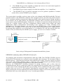
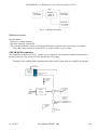
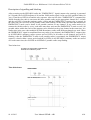
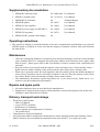
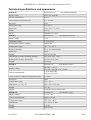
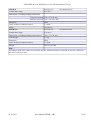
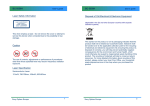
ZAM-SERVIS s.r.o. Křišťanova 1116/14 Ostrava-Přívoz 702 00
User Manual
Underground Communication and Alarm System
SEFAR - AB1
No. 1096
This User Manual includes:
Instructions for assembly, installation, commissioning, use, operation, settings, maintenance and
servicing, disassembly, disposal and technical conditions.
Keep this manual for future use.
01.10.2013
User Manual SEFAR - AB1
1/14
ZAM-SERVIS s.r.o. Křišťanova 1116/14 Ostrava-Přívoz 702 00
Contents
User Manual...................................................................................................................................................2
Use.................................................................................................................................................................2
Description and functions..............................................................................................................................2
Installation and assembly...............................................................................................................................7
Supplementary documentation.......................................................................................................................8
Operating instructions....................................................................................................................................8
Maintenance...................................................................................................................................................8
Repairs and spare parts..................................................................................................................................8
Delivery, transport and storage......................................................................................................................8
Fire safety, ecology, disposal, recycling........................................................................................................9
Manufacturer and service organization..........................................................................................................9
Related standards, regulations and documents..............................................................................................9
Technical specifications and appearance.....................................................................................................10
Figures enclosed...........................................................................................................................................12
Document revision.......................................................................................................................................14
User Manual
This User manual includes instructions for assembly, installation, commissioning, use, operation, setting,
maintenance and servicing, disassembly and disposal, and technical specifications.
All workers installing, putting into operation, operating, maintaining and servicing the unit must be
demonstrably familiarized with these operating instructions. Keep this manual for future use.
Use
•
The Underground Communication and Alarm System is intended for provision of voice
communication and safety in the area worked, belt conveyor areas, but also in all the other mine areas
and it meets the following functions:
a) Semi-duplex, single-channel voice communications between portable SEFAR-C radios (hereinafter
radios only).
b) Mining machine blocking using the disconnect switch from all the radios within reach of radio
communication.
Description and functions
•
The SEFAR-AB1 system communication frequency is in the l62 to l72 MHz band. The system
consists of the following components:
1.
- The portable radio, identified as SEFAR-C type, serves for voice communications among
workers working underground and for mining machinery halt
2.
- The stationary radio, identified as SEFAR-B1 type, serves for bi-directional communications
of portable radios through the radiating antenna; it analyses the requirement for mining
machinery halt and it opens the appropriate control contact and for connection to intrinsically
safe phone line or to the one not intrinsically safe
3.
- The radiating VLCAY coaxial cable of 50Ω impedance serves as the antenna
4.
- The SEFAR-KC 0l type of terminator for antenna termination
5.
- The splitter, identified as SEFAR-R type, serves for connection of other SEFAR-B1
stationary radios to increase the number of channels or to distribute the antenna routes.
01.10.2013
User Manual SEFAR - AB1
2/14
ZAM-SERVIS s.r.o. Křišťanova 1116/14 Ostrava-Přívoz 702 00
6.
7.
- The SEFAR-LZ type of line amplifier to amplify the levels of voice and control signals for
communications at distances exceeding 350m
8.
- The SEFAR-Z type of power supply to feed the line amplifiers. (1 to 19 amplifiers)
- The SEFAR-GO type of galvanic separation serves for galvanic separation of antenna
sections fed by various SEFAR-Z power supplies
The system makes it possible to select as many as four voice channels with l5kHz bandwidth. The basic
structural member is the SEFAR-B1 stationary radio equipped with the 100-350m long antenna and the
KC-01 terminator enabling communication between portable radios and blocking the mining machinery
on one channel. For any other channel, one SEFAR-B1 stationary radio is necessary which is connected
in the system using the SEFAR-R splitter. Furthermore, it enables to transmit the mining machinery halt
signal on a separate channel. The basic configuration without antenna power supply and signal
amplification enables communication and blocking in the working up to 350m, according to the
installation site. For longer distances, you need to insert the SEFAR-Z type of power supply and the
SEFAR-LZ type of amplifiers in the system and you can extend communication over a longer distance.
By inserting other amplifiers, up to a total number of 19 (9 amplifiers for each side from the basic one,
which is fed by an intrinsically safe SEFAR-Z power supply), you can cover a distance of 6650m.
Power
230VAC/50Hz
SEFAR C
Portable
radio
KC 01
Term inator
SEFAR B1
Stacionary
radio
SEFAR C
Portable
radio
Emergency (mining machinery blocking)
Voltage-free contact
Antenna
lenght 100-350m
SEFAR C
Portable
radio
Basic wiring of Underground Communication and Safety System
SEFAR-B1 stationary radio (I M2(M1) Ex d [ia] I)
The stationary radio electronics is implemented on dual layer PCBs. The STACRX, STACBL receivers
and the STACTX transmitter are a reduced version of portable radio electronics. The electronic PCBs are
housed in the box - explosion-proof enclosure along with the power supply. The power supply is fed from
230V mains. The antenna (radiating cable) is connected to the communication part through blocking
capacitors – RF type of bushings for application of the parasitic antenna.
Moreover, the EMERGENCY blocking command for mining machinery halt is taken from the
communication part and one voltage-free contact for controlling from the portable radio or for indication
of other states is taken through the PD D36 type of bushing. In the communication part there is a glass
window where you can see a LED indicator, indicating the operational status of the system and the
display, showing the selected communication channel and other settings as well as the system status. This
information items vary on the display after every 2 seconds approximately. .
01.10.2013
User Manual SEFAR - AB1
3/14
ZAM-SERVIS s.r.o. Křišťanova 1116/14 Ostrava-Přívoz 702 00
SEFAR-C portable radio (I M1 Ex ia I)
In order to operate the SEFAR-C radio, you need to switch on the SEFAR-B1 stationary radio!
How to switch on SEFAR-C: The radio is put in operation by turning the volume knob from its leftmost
to its rightmost positions. After some 1 sec, the SEFAR-C radio is ready for operation in receiving mode.
Reception: the SEFAR-C signal reception mode, volume increasing/decreasing is performed by turning
the volume control knob to the right/left.
Transmission: If you wish to transmit, press down the PTT button; the LED indicator is lit in red and then
you can speak to the microphone. You must keep the PTT button pressed down for the entire period of
transmission. Transmission is terminated as soon as you release the PTT button / SEFAR-C is switched to
reception mode/.
EMERGENCY (mining machinery blocking): By pressing down and holding the EMERGENCY button
for about 3 sec, the blocking function is activated. The SEFAR-C transmits the blocking signal every 3
seconds and it is further processed in the stationary radio. The blocking mode is indicated by flashing the
red LED indicator and by EMERGENCY lettering on LCD display. . In this SEFAR-C operational mode
you can receive and transmit, but you need to count with interruption of communication after every 3
seconds for a period of some 250msec. The EMERGENCY mode is cancelled by switching off the
portable SEFAR-C radio and switching it on.
Voltage-free contact controlling: In the SEFAR-C radio menu, you can control the voltage-free contact on
the SEFAR-B1 stationary radio (you can take out as many as four such contacts), by which means you
can implement any signalling or safety function in connection with an evaluation system connected to this
contact.
To switch off the SEFAR-C radio: The radio is switched off by turning the volume knob to its leftmost
position.
SEFAR-R splitter
It is used for splitting the radiating antenna in underground roads It is housed in a plastic box and it has 3
bushings for connecting the antenna cable. For assembling, refer to the diagram below. The maximum
length of the coaxial cable between 2 SEFAR-LZ intermediate amplifiers is up to 350m according to the
installation site. This situation is indicated in Fig. 2. When using the SEFAR-R splitter between the
appropriate intermediate amplifiers /before and after splitting/ additional 4dB attenuation is inserted. That
is why you need to cut the length of the coaxial cable between 2 SEFAR-LZ intermediate amplifiers by
70m against the version without the splitter. This situation is indicated in Fig. 3.
SEFAR LZ_1
line amplifier
SEFAR LZ_2
line amplifier
Fig. 2: Cabling without splitter
01.10.2013
User Manual SEFAR - AB1
4/14
ZAM-SERVIS s.r.o. Křišťanova 1116/14 Ostrava-Přívoz 702 00
SEFAR R_1
splitter for
SEFAR_LZ
SEFAR LZ_1
line amplifier
SEFAR LZ_2
line amplifier
SEFAR LZ_3
line amplifier
Fig. 3: Cabling with splitter
Radiation antenna
Specifications:
- Solid core 2.24mm diameter
- Dielectric medium, foamed PE
- The external conductor consists of conductors laid down, with the total cross-section of 3.8mm2
−The cable jacket is made of softened PVC in yellow (black or grey) colour
SEFAR-KC0l terminator
The terminator is made up of a 50Ω resistor, series connected, 2n2 capacitors and the terminal board
located in the box. The unit is in Ex ia I intrinsically safe design.
Example of the underground communication and security system with one amplifier and splitter
Power
230VAC/50Hz
SEFAR B1
Stacionary
radio
Emergency (mining machinery blocking)
Voltage-free contact
Antenna
SEFAR C
Portable
radio
Power
230VAC/50Hz
(60VDC)
SEFAR Z
SEFAR LZ
Line amplifier
Power
supply
SEFAR C
Portable
radio
SEFAR GO
Galvanic
separator
SEFAR C
Portable
radio
SEFAR R
Splitter
KC 01
Terminator
01.10.2013
User Manual SEFAR - AB1
5/14
ZAM-SERVIS s.r.o. Křišťanova 1116/14 Ostrava-Přívoz 702 00
Description of signalling and blocking
After powering up the SEFAR-B1 radio, the "EMERGENCY" signal (output relay opening) is generated
in 5 seconds, the red LED indicator is lit and the 300Hz audio signal is sent out to the portable radios for
3secs. Then the red LED is off and the relay operates. After arrival of the "EMERGENCY" command, the
300Hz from the first radio is sent out to the other portable radios on the appropriate channel for 3 seconds
and the red LED is lit on the stationary radio / radios and the EMERGENCY output relay is opened. At
the same time, the red LEDs on all portable radios start flashing. In this mode, the radio that initiated the
EMERGENCY mode can be heard in all portable stations on any channel. If any radio needs to be
connected with this radio by voice, such radio must have activated the EMERGENCY mode as well. All
portable radios within the reach of the antenna can be blocked on the given channel at the same time. It is
similar also in the case when multiple SEFAR-B stationary radios with different channels are used. When
the EMERGENCY signal is transmitted from any radio on any channel, the EMERGENCY output relays
in all SEFAR-B1 stationary radios operate and red LEDs in all radios on all channels used will be
flashing. After the EMERGENCY mode in all portable radios is terminated, the EMERGENCY output
contact is closed within a preset period and the red LEDs in all SEFAR-B1 stationary radios are turned
off. At the same time, the red LEDs in all SEFAR-C portable radios stop flashing.
Time behaviour:
BLOCK from stationary radio
Time behaviours:
BLOCK from helmet
3 kHz from stationary radio
UNBLOCK from stationary radio
Machine operation
01.10.2013
User Manual SEFAR - AB1
6/14
ZAM-SERVIS s.r.o. Křišťanova 1116/14 Ostrava-Přívoz 702 00
Installation and assembly
•
The stationary radio is usually located in the protective bay at the entrance to the underground mining
workplace. The explosion-proof enclosure is attached to a suitable steel structure using four M8
screws; the retainers are part of the radio enclosure. The line voltage is brought through the disconnect
switch into the relevant bushing in the terminal board section. The information to stop (blocking) the
mining machine (drive) is accomplished as an intrinsically safe output (voltage-free relay contact).
The same applies to the other output controlled from the portable radio. The output for the special
radiating coaxial cable is also in intrinsically safe design. These intrinsically safe cables (blue part of
the enclosure) must be kept apart from the power cables spatially and they must be led separately. The
explosion-proof entry bushings are sealed and fastened down; the cables from outlets are suitably
attached.
•
Antenna (coaxial cable) installation.
1. The antenna is placed in the laying of cables for the powered support into the upper layer. It
must be laid freely with allowance for movement of supports.
2. The antenna must be attached in an insulated way; it must not be attached using metal hooks
and binding wires. The terminator is connected to one end of the antenna. The other end of the
antenna is connected to the appropriate terminals of the stationary radio.
Before the cable is put into the PNV outlet, it is necessary to slacken 2 socket head screws so that the
clamp and the sealing ring cannot prevent the cable from insertion in the enclosure. The contact
surface of the cable casing with bushing must be cleaned from any dirt and inserted into the bushing
in such manner that the casing end protrudes over the plane of flange surface by 8mm at least. Screw
in the bushing body carefully and tighten the rubber sealing ring. That will expand the O-ring and seal
the cable inside box. Then insert the bushing with a sleeve and place the blocking device from the top.
The blocking device is screwed into the bushing body over the sleeve using 2 screws. That ensures
blocking the cable against mechanical tearing out of the box. The blocking cog serves as a safety to
prevent unauthorised disassembly of bushing from the box.
Unused outlets must be blinded with original caps.
M8 screws on the lid must be tightened to the prescribed torque of 7-9 Nm after completion of the
installation.
There may be no loose conductor ends.
All screws on appliances and terminals inside the rack must be tightened properly. This also applies to
unused screws.
Length of wire stripping:
1. WAGO 281
1. cross-section of connected wires 0.08 mm2 to 4 mm2.
2. length of wire stripping 9 mm to 10 mm.
3. terminal opening tool: flat screwdriver sized 3.5 mm x 0.5 mm.
•
•
•
•
•
•
01.10.2013
User Manual SEFAR - AB1
7/14
ZAM-SERVIS s.r.o. Křišťanova 1116/14 Ostrava-Přívoz 702 00
Supplementary documentation
1. SEFAR-B1 stationary radio
No. 20009-000 User Manual
2. SEFAR-C portable radio
No. 21219-00
User Manual
3. SEFAR-KC01 terminator
No.
Technical Report
4. SEFAR-R splitter
No. 20617
User Manual
5. SEFAR-LZ line amplifier
No. 1096/1
User Manual
6. SEFAR-Z power supply for SEFAR-LZ
No. 1096/2
User Manual
7. SEFAR-GO separator
No. 20701
User Manual
8. SEFAR-NAB 1 portable radio charger
No.
Operating instructions
•
The operator is obliged to check the function of the unit, communication and blocking every time the
SEFAR system is switched on. In the case that the integrity of antenna is broken, they must eliminate
the fault at first.
Maintenance
•
•
•
•
Check the sealing and condition of explosion-proof enclosure bushings; check the coaxial antenna
route, including the KC 01 terminator. Keep the glass window in the enclosure clean. Apply a thin
film of grease - plastic grease NH2 or K4 (red vaseline) to surface contacts of the explosion-proof
enclosure.
Keep the surface clean, any dirt and dust must be removed using a piece of clean and dry cloth, a
brush or broom, further cleaning of the surface must be done using a piece of damp cloth.
When unit is operated, make sure that impurities and dust cannot get into the module through air
vents as these impurities may be electrically conductive and may affect the intrinsic safety of the
level meter. Remove dust and moisture (leakage) from contact sensors.
The manufacturer determines regular inspections one a year carried out by ZAM Servis s.r.o.
workers or by their authorized representative.
Repairs and spare parts
•
•
All repairs and spare parts are provided by the manufacturer.
Equipment for repairs must be properly cleaned and have enclosed description of the defect and
conditions, under which defect is shown.
Delivery, transport and storage
•
•
•
The delivery shall include:
• This User Manual
• Copy of FTZÚ certificate
• Declaration of Conformity.
• Product Quality and Completeness Certificate.
• The product itself.
Components are delivered unpacked.
All components shall be transported with attention to reduce potential shocks and vibrations. Items
shall be stored in dry environment at temperature between 0 and 40 oC in a single layer only.
01.10.2013
User Manual SEFAR - AB1
8/14
ZAM-SERVIS s.r.o. Křišťanova 1116/14 Ostrava-Přívoz 702 00
•
The delivery includes:
•
This User Manual
•
A copy of the Declaration of Conformity
•
The product itself
Fire safety, ecology, disposal, recycling
•
•
•
Do not expose to open flame; harmful substances are produced by burning.
When used properly during operation it doesn’t affect the environment and ecology.
After expiration of the lifetime, return the product to the manufacturer for disposal. The address is
given in this document.
•
After expiration of the lifetime, the electrical and electronic equipment must not be
disposed of as ordinary municipal waste. The product must be forwarded to a relevant
collection point for proper processing, regeneration and recycling of the electrical and
electronic equipment.
•
For more information about the collection point and recycling of this product, please
contact the local authorities, a municipal waste management firm at your place or the
shopkeeper where you purchased this product.
Manufacturer and service organization
•
ZAM - SERVIS s.r.o. Křišťanova 1116/14, 702 00 Ostrava - Přívoz, phone: 596 135 422 e-mail:
[email protected]
Related standards, regulations and documents
LVD:
ČSN 33 2000–4–41 ed.2:
Low voltage electrical installations – Electric installations – Part 4: Safety –
Chapter 41: Protection against electric shock.
ČSN EN 60529
Degrees of protection provided by enclosures (IP Code)
ATEX:
ČSN EN 50303
Group I, Category M1 equipment intended to remain functional in
atmospheres endangered by firedamp and/or coal dust
ČSN EN 50394-1
Electrical apparatus for potentially explosive atmospheres - Group I Intrinsically safe systems
ČSN EN 60079-0 ed.4
Explosive atmospheres – Part 0: Equipment General requirements
ČSN EN 60079-1 ed.2:
Explosive atmospheres - Part 1: Equipment protection by flameproof
enclosures „d“
ČSN EN 60079-11 ed.2:
Explosive atmospheres – Part 11: Equipment protection by intrinsic safety
“i”.
ČSN EN 1127-1 ed.2:
Explosive atmospheres – Explosion prevention and protection – Part 1:
Basic concepts and methodology
ČSN EN 1127-2 + A1:
Explosive atmospheres - Explosion prevention and protection -Part 2: Basic
concepts and methodology for mining
01.10.2013
User Manual SEFAR - AB1
9/14
ZAM-SERVIS s.r.o. Křišťanova 1116/14 Ostrava-Přívoz 702 00
Technical specifications and appearance
SEFAR-B1
Find out more in:
Supply voltage
230 V AC 50/60 Hz
Current consumption:
0.35 A
Cross-section of connected wires
1.5 – 2.5 mm2
Protection
IP 54
Temperature range
0 to +40 °C
Dimensions
230 x 530 x 177 (mm)
Weight
23.5 kg
Design
I M2(M1) Ex d [ia] I
SEFAR-C
Find more in:
Rated voltage
7.4 V
Operating voltage
5.5V to 8.4 V
Rechargeable battery capacity
2800 mAh
Temperature range
-20 oC to +50 oC
Relative humidity
95 %, no condensation
Protection
IP 54
Design
I M1 Ex ia I Ma
Dimensions of radio, including antenna
247.5x62.5x41.5 mm
Rechargeable battery dimensions
92.0x56.0x25.0mm
Weight
0.298 kg
SEFAR-Z
Find more in:
Supply voltage
60 VDC +-10 %
230 VAC (90-240 V AC), 50Hz
Current consumption:
0.16 A at 60 VDC
0.05 A at 230 VAC
Cross-section of connected conductors, max.
2.5 mm2
Protection
IP 54
Temperature range
0 to + 40 °C
Dimensions (w x h x d)
240 x 430 x 145 mm
Weight
12.5 kg
Design
I M2(M1) Ex d [iaMa] I Mb
SEFAR-LZ
Find more in:
Supply voltage
9-12 V / DC
Current consumption:
approx. 10 mA
Temperature range
-20 °C to +40 °C
Dimensions
79 x 236 x 75 mm
Weight
0.42 kg
Design
I M1 Ex ia I
01.10.2013
User Manual SEFAR - AB1
User Manual 20009-000
User Manual 21219-00
User Manual 1096/2
User Manual 1096/1
10/14
ZAM-SERVIS s.r.o. Křišťanova 1116/14 Ostrava-Přívoz 702 00
SEFAR-R
Find more in:
Temperature range
0 to 40 °C
User Manual 20617
Dimension, excluding bushings and aerials
Polyester housing 110 x 75 x 58 mm
Stainless steel box 130 x 130 x 65 mm
Protection
IP54
Cross-section of connected wires
2.5 mm2
Design
I M1 Ex ia I
SEFAR-GO
Find more in:
Temperature range
0 to 40 °C
Dimension, excluding bushings and retainers
190 x 75 x 58 mm
Total weight
0.3 kg
Protection
IP54
Cross-section of connected wires
2.5 mm2
Design
I M1 Ex ia I Ma
User Manual 20701
EMC:
According to ČSN EN 61 000-4-2, ČSN EN 61 000-4-3, ČSN EN 61 000-4-4, ČSN EN 61 000-4-8, ČSN EN 61
000-4-11, ČSN EN 55 022.
01.10.2013
User Manual SEFAR - AB1
11/14
SEFAR B_1-4
Stationary
radio
User Manual SEFAR - AB1
SEFAR R_1
Rozbočovací
člen
SEFAR KC-01
Koncový člen
SEFAR R_2
Rozbočovací
člen
Terminator
SEFAR R_3
Rozbočovací
člen
SEFAR B1_1
Stacionární
radiostanice
SEFAR B1_2
Stacionární
radiostanice
SEFAR R_3
Splitter
SEFAR B_1-3
Stationary
radio
SEFAR R_2
Splitter
SEFAR B_1-2
Stationary
radio
SEFAR R_1
Splitter
SEFAR B_1-1
Stationary
radio
SEFAR B1_3
Stacionární
radiostanice
SEFAR LZ
Linkový
zesilovač
SEFAR Z-IS
N apájecí
zdroj
SEFAR Z-IS
Power
supply
SEFAR LZ
Line amplifier
SEFAR C _1
R uční
radiostanice
SEFAR C_1
Portable radio
01.10.2013
SEFAR B1_4
Stacionární
radiostanice
SEFAR C _2
Ruční
radiostanice
SEFAR C_2
Portable radio
Solution for 4 channels
Řešení pro 4. kanály
ZAM-SERVIS s.r.o. Křišťanova 1116/14 Ostrava-Přívoz 702 00
Figures enclosed
Fig. 3 Example for four-channel wiring
12/14
ZAM-SERVIS s.r.o. Křišťanova 1116/14 Ostrava-Přívoz 702 00
Fig.8: SEFAR-B1
Fig.10: SEFAR-LZ
Fig.11: SEFAR-KC01 and SEFAR-R
Fig.12: SEFAR-C
01.10.2013
Fig.9: SEFAR-Z
Fig.13: SEFAR-NAB1
User Manual SEFAR - AB1
13/14
ZAM-SERVIS s.r.o. Křišťanova 1116/14 Ostrava-Přívoz 702 00
Document revision
20/05/2005 Initial document version
14/10/2013 Reformatting and supplementation of text, variation in figures
01.10.2013
User Manual SEFAR - AB1
14/14