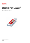
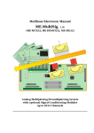
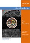
1
Infrared coupled IrDA compatible MINIATURE DATA LOGGER FAMILY RedCube Version 1.4 USER MANUAL Table of Contents 1. 2. 3. 4. 5. Getting Started Preparing, Starting and Switching-off the Data Logger Reading and Displaying Measured Values Technical Specifications Appendix Page 2 MINIATURE DATA LOGGER FAMILY RedCube User Manual 1. Getting Started The RedCube data logger series is designed to measure and store with internal sensors: • Temperature with 0.1°C resolution RedCubeTEMP • Temperature and relative humidity combined RedCubeCLIMA • Vibration and motion RedCubeVIBRA • DC voltage RedCubeVOLT • Impulse counting RedCubePULSE • Shock, acceleration, temperature RedCubeAXEL° Each miniature data logger contains a specific sensor for the respective measurements. It is possible to start the measuring program immediately or with a delay of up to 6 months. The measuring period is programmable between 1 second and 24 hours with a precision of one second. The acquired data is stored internally for long periods of time (>10 years). Each data logger contains an infrared interface (compatible to the IrDA standard) for the wireless communication and data exchange with PC or laptop. Due to the design philosophy of RedCube as an autonomously working device there are no external wires necessary. Windows software to configure the measuring program and to transfer PC-data is provided. Additionally, a licence for all software interface commands to control RedCube is available. These commands enable developers to create their own RedCube applications. RedCube regular is mounted into a red plastic cube case (31 mm x 31 mm x 31 mm). The required battery voltage is 3.0 … 3.6 V (recommended type of battery: ½ Mignon, Lithium 3.6 V, 950 mAh). The operating life of the battery is dependent on its type, the mode of measurement, sampling time and number of data transfers from and to the PC or Notebook computer. In fact, it is possible to achieve a battery life span of up to several years. RedCube is consuming electrical power only during operation mode (app. 300µW per second while measuring, app. 7 mW for the whole data transfer operation). Otherwise, the device switches into stand-by mode, which has extremely low power consumption (only some µW). Therefore, the RedCube data logger series has no on/off-switch. By means of the provided software, the user can set-up the power-down mode or choose to use the automatic defaults. The internal battery is mounted changeable to the data logger. Apart from the normal RedCube version, an OEM-version, specific casing modifications and complex systems are also available. Supplied Components and optional accessories Supplied components of the RedCube-family are: • Miniature data logger with replaceable battery • Lithium battery Page 3 MINIATURE DATA LOGGER FAMILY RedCube User Manual • • CD-ROM containing software to control and read out the RedCube data logger (Windows 2000/XP/Vista/Windows 7) and the user manual (pdf-file) This user manual as hardcopy (optional) Disposal of the data logger Disposal of the data logger requires your help with the disposal to protect our environment and you must pay attention to the legal rules: The normal disposal of old electronic devices is the legal obligation of manufacturer and customer equally. Electronic industry waste may not be disposed in the garbage can! These old devices may not be returned in public withdrawal systems but must be brought to the dealer or manufacturer directly. Traders and manufacturers accept the old devices free of charge to the disposal/recycling. Preparing the data logger for use Setting necessary devices in operation For initialisation of the RedCube measuring program and to start the logger a PC or Laptop with an adapter (USB or serial port) to IrDA (can be ordered from the dealer or manufacturer) or an integrated IrDA interface is required. For successful operation please set up this IrDA interface in the PC-BIOS to “Infrared-COM”. Please refer also to the respective chapter and appendix in this manual provided. Please test this IrDA adaptor separately before installing the RedCube software. Inserting and changing the battery The RedCube will be delivered including a battery. The battery-lifespan ranges from some months up to several years. Stored data is held even without a battery. Important note on disposal: The normal disposal of batteries and accumulators is a legal obligation. In the devices existing batteries are to be delivered at the end of their use to public return places or sales offices. The battery is to be inserted before the first use of the logger. When inserting or changing the battery attention has to be paid to the indications present at the device. The use of an inappropriate battery voltage or a wrong polarity of the battery can lead to a defect of the data logger. Steps for battery change of RedCube Remove the cap or half bowl which does not contain the infrared diodes (2 eyes). You can also use a small screwdriver if necessary (Attention: don´t damage existing O-ring seal and housing bowl!. Draw off the old battery from the contacts. Insert the new battery correctly poled. Pay attention to correct fix placement. Test the Logger with still opened housing and repeat the battery replacement to cleanly reset the logger. Close the hous- Page 4 MINIATURE DATA LOGGER FAMILY RedCube User Manual ing after a successful test. Pay attention to the correct arrangement of the lamellas fastening the battery in the half bowl (danger of destroying case). Note: Please, ensure proper polarity of the changed battery and do not damage the printed circuit board, because this can destroy the logger. Preparing of PC to communicate with the logger First, start Windows on your PC. PC and measuring logger communicate via an IrDA infrared interface. It is to be guaranteed that the infrared interface compatible to the IrDA standard is properly installed. It guarantees the necessary data exchange. In addition to the communication between PC and data logger, correct installation of the RedCube software is necessary. Furthermore, check if your computer is using the correct time and date. This fact is crucial, because these settings will become the time base of your data logger. Installing the data logger software Please insert the provided CD-ROM into your PC´s CD-ROM drive. The installation routine of the data logger software may be started by choosing the Windows start button. Go to “Run”, type ”[drive]:\setup.exe” (where “[drive]:\” is the letter for your CD-ROM drive), click OK and follow the on-screen instructions. After confirmation of the destination directory (e. g. c:\programs\logger) the installation will be completed. As a result of a successful installation, the program group Logger with the program icon Logger is listed as an entry in the programs menu of Windows. The software can be executed by double clicking the Icon on the Windows desktop (with the left-hand mouse button) or may be selected in start/programs. Please note: Before installing new logger software please uninstall older versions from your PC. Please note that you should have administrator's rights on the concerning PC during installation. Page 5 MINIATURE DATA LOGGER FAMILY RedCube User Manual 2. Preparing, Starting and Switching-off the Data Logger The RedCube software offers the following possibilities to control the data logger, to configure the measuring program and to read out the data: • Initialisation of the data logger (defining of absolute time, sample period, start time, optional threshold values and measurement cycle name) • Start of a new data logging sequence • Downloading the data stored in the data logger • Visualisation of the data in graphical and tabular form • Printing of data graphs for one or more data loggers • Export data into MS EXCEL-compatible ASCII format • Switching off the data logger by software • Online display of current values via PC/Notebook 2.1 Data Logger Software and PC-Data Logger Communication Executing the RedCube data logger software in Windows is done by double-clicking the left hand mouse button on the Logger-icon or by selecting the Logger software from the entry Start/Programs. The main window of the Data Logger Software appears with the following main tool bar buttons 1. Exit 2. Open 3. Logger Quits the PC data logger program Loads already stored measurement data files (*.cu2) Search, read out, configure, start the data logger and display current values 4. Tabular Alpha-numeric display of measurement values in tabular form 5. Graphic Graphical display of measurement values 6. Export Export for activated measurement values (*.xls) 7. Setup Basic settings of parameters, software version-information 8. Help Online-help to use the data logger software (manual in PDF form) In most of the cases by pressing the button Logger a connection to the data logger has to be established. For the connection a succesful installed compatible IrDA interface is required. To establish this connection automatically, at least one logger has to be placed in front of the IrDAinterface. The data logger has to be placed in such a way, where its infrared diodes (“two eyes”) are facing the infrared interface or adaptor of the PC with 10 to 50 cm distance. Only if in the task bar below on the right the IrDA symbol appears or the message “Another computer is in range” is displayed, a succesful connection is possible. Please note: The IrDA interface of the PC tries periodically, to hold the IrDA connection with the logger, even if the RedCube software is not active. The logger in Page 6 MINIATURE DATA LOGGER FAMILY RedCube User Manual the communication mode has a high energy consumption. If no communication is required it is strongly recommended to put the logger outside the range of the infrared IrDA adapter. 2.2 Selection of the Data Logger Activating the Button Logger in the main window, the logger-window is shown: The logger identification is either automatically done by selecting one or more data loggers found or by manual input of the required logger IDnumber. To avoid errors in the data communication put the infrared adapter and the data logger close together and direct the transmitter and receiver diodes facing each other. Please note: The infrared diodes are positioned in the cube housing behind the “eyes”. Automatic Selection The identification (ID-number) of n data logger is done automatically during connection establishment between PC and data logger, if the selection Search for [n] logger is activated and the number n is entered. The software selects the data loggers found and registers their ID-numbers. Please note: Don´t search for more than two loggers at the same time, because of shared performance and the increasing power consumption. If the communication or data transfer is disturbed, error messages will be displayed indicating the problem. At any time it is possible to re-establish the connection. Please note: The time needed to establish a connection with a data logger can last up to 20 seconds. The contacted loggers are listed by the status (found[closed book]/read out[opened book]/started[walking man]/started but measurements pending[standing man]), ID-number, logger name and type, memory capacity and the current level of memory utilization. If the mouse pointer is moved and held on the symbols, the description is displayed. Page 7 MINIATURE DATA LOGGER FAMILY RedCube User Manual Loggers can be selected from the table shown in the figure above, configured, started, switched off via software or their current values can be displayed on-line. This is done for individual loggers via the buttons in the appropriate row. Activities for all listed loggers can be set by selecting the buttons Read all and Start all. Activating the Button Remove all will delete all loggers from the table. An individual logger can be removed from the table by clicking the right mouse button on the respective row and choosing the appearing button Remove. Please note: If there are problems to find the logger please check the IrDA connection and the settings. For your IrDA dongle in the device manager/IrDA devices set the minimum processing time 0.5 ms. 2.3 Starting the Data Logger Before starting the logger it is necessary to configure the measuring sequence (see section 2.5). To configure it for a new measuring sequence it must be listed in the table. Press the button Start in the corresponding row of the logger. A window appears with parameters to configure. The data logger will be started by activating the Execute button. The program checks the entered parameters and contacts the logger. There are a series of status reports, concerning the starting logger. If you only close the window, the logger does not start. Please note: Each read operation terminates a current measuring sequence. If the measuring program is to be continued, the logger has to be started again. 2.4 Switching off the Data Logger If the logger is not in use for some time, it is recommended to set the logger to minimal energy consumption mode, to reduce the impact on battery life. To achieve this, simply read out the respective loggers. The measurement programme will be stopped. To avoid all infrared contacts, please remove the logger from the range not only of personal computers, but also of all devices with infrared interfaces (PDA, cell phone, etc.). Page 8 MINIATURE DATA LOGGER FAMILY RedCube User Manual Please note: Contacts betwen the logger and the IrDA adaptor of the PC need energy, even if the RedCube software is not activated. 2.5 Preparing the Data Logger for a Measuring Sequence To configure the data logger for a new measuring sequence it must be listed in the table. Press the button Start in the corresponding row of the logger. If you want to configure more than one logger of the same type in the same time, you may activate the button Start all in the upper part of the window. After successfully connecting to the data logger (temperature, clima, vibration, pulse or voltage) a window opens for the respective type of logger. It contains general data about the specific logger such as logger-ID, logger-type (TEMP, CLIMA, VIBRA, PULSE, VOLT), measuring range and memory capacity. All parameters necessary for the measuring sequence are editable. Some of these parameters are common to all data logger types: Field Settings: Logger-Name [optional] Each measuring sequence can be named by editing a string of up to 16 characters in the field Logger-Name. This name will be assigned to the measured values. Please note: Avoid special characters, otherwise problems can occur when data is exported. Field Settings: Begin of Measurements / Start time / From: Two start options are available through the menu: Start immediately and Start delayed. After removing the sign next to Start without delay field, the contents of the Start field can be edited using the format dd.mm.yyyy (day.month.year) and hh:mm:ss (hour:minute: second). The maximum delay possible is 6 months. If the edited start time is incorrect, no To date is displayed and the entered time is reset. Using a past time as value in the From field is not permitted. The default setting is to start the measuring sequence immediality ( at Start without delay), you can see the current PC time as the start time. Page 9 MINIATURE DATA LOGGER FAMILY RedCube User Manual Please note: All entries of the time refer to the current PC time. At the start of the logger, the current PC time is transmitted and now becomes the time basis of the logger. Therefore a properly adjusted PC time is very important. Field Settings: Measuring period / Sampling rate: The sampling period can be specified in the corresponding field with hours, minutes and seconds [hh:mm:ss]. Valid values range from 1 second to 24 hours. If the registered interval is within the allowed range, the corresponding end time is automatically calculated and displayed in the To field. This time represents the moment, when the build-in memory of the data logger is completely filled. If the sampling period specified is incorrect, no date is displayed and the entered value is reset. Editing of the data values is also possible by marking (left mouse button) the number pairs and counting up or down by pressing the left mouse button. Please note: The default setting of measuring period / sampling rate is 1 s. Settings: End of Measurements / To: If the start time and the sampling period are within the allowed range, the corresponding end time is automatically calculated and displayed in the To field. This time represents the moment, when the build-in memory of the data logger is completely filled. The measuring sequence will then be stopped and the data will be saved until read out. It is possible to finish the measurements earlier by reading out the data. Memory Size The number of samples stored in the logger depends on its build-in memory, but also on the resolution of the samples to be taken. The following example of a temperature-logger shows the times needed to fill a memory of 32 Kbyte with a value accuracy of 0.1°C using different sampling periods: Sampling period every second one measurement every minute one measurement every hour one measurement ....... every day one measurement Fills a 64 kByte memory after 9 hours 22 days, 17 hours 44 months, 26 days ....... theoretically more than 63 years (but battery would be discharged by then) For different resolutions and memory capacities, these estimates change accordingly. You can close the program window without start by clicking the button Close. Page 10 MINIATURE DATA LOGGER FAMILY RedCube User Manual 2.5.1 RedCubeTEMP Temperature Data Logger (Resolution of 0.1°C) Logger-specific settings: Selecting the Resolution of Measured Values RedCubeTEMP can be configured for two different value resolutions: 0.1°C and 0.5°C. The storage capacity depends directly on the selected resolution. For instance, using a 0.1°C resolution will allow approximately 16,000 values to be taken, whereas a 0.5°C would permit approximately 32,000 samples.. Start on Temperature Threshold An alternative way to trigger the measuring program is to specify two different temperature threshold values (upper and lower). If the temperature moves outside of this temperature band, the logger will start the logging process. In order to activate this option, in the field Threshold the sign in the Account for box has to be ticked. Please note: The data logger is only usable in its operating temperature range, –40 ... +85°C in standard range or –40... +120°C for data logger with extended temperature range. Operating the data logger outside of its allowed temperature range can lead to its destruction. Page 11 MINIATURE DATA LOGGER FAMILY RedCube User Manual 2.5.2 RedCubeCLIMA Combined Logger for Temperature / Humidity Besides the already described inputs the following additional parameter settings are important for the combined temperature/humidity-logger: Select temperature-humidity The logger is able to measure only temperature or only humidity or both temperature and humidity. Please activate the selected parameters by setting . Start on Thresholds Additionally to the option of a delayed start, the logger can also start logging upon reaching a programmable threshold value (upper and lower). Please activate Account for in the frame Threshold and type the upper and lower limit values (default: upper= 30, lower =20). Please note: In order to enable a quick response of the data logger, the build-in sensor is partially unprotected within the casing. Therefore, the logger should be hand-led carefully in order not to damage the sensor. Water drops on the sensor distort the measurements! 2.5.3 RedCubeVIBRA - Logger for Vibration and Motion Besides the start time and the sampling period, there are no further parameter settings. Please note: Within a measuring period up to 65,534 pulses can be acquired. Page 12 MINIATURE DATA LOGGER FAMILY RedCube User Manual 2.5.4 RedCubeVOLT – Logger for DC Voltage Logger-specific settings are: Start on Voltage Thresholds As well as having the option of a delayed start, it is also possible to start the measuring sequence depending on an upper as well as a lower voltage threshold. To activate this option in the frame Thresholds, click the box Account for. The values are to be edited in the corresponding fields Upper limit and Lower limit (default: upper=2.00 V, lower=1.00 V). 2.5.5 RedCubePULSE - Logger for pulse counting Besides the already described inputs the following additional parameter settings are important for the pulse logger: Calibration In order to assign the counted pulses to the actual measured value it is necessary to calibrate the logger. By left-clicking on Calibrate in the Start menu window a new window for calibration will be opened. This presents the initial count, the decimal places, a factor for the pulse value (eg: 1 pulse = 10m3 or 1 pulse = 10 kW) and the unit for the measured value. Left-clicking on calibrate starts the calibrating process. Page 13 MINIATURE DATA LOGGER FAMILY RedCube User Manual 2.5.6 RedCubeAXEL° - Logger for shock, acceleration, temperature Besides the already described inputs the following additional parameter settings are important for the combined temperature- and acceleration-logger: Select temperature-acceleration The logger is able to measure only temperature or only acceleration or both temperature and acceleration. Please activate the selected parameters by setting . Start on Thresholds Additionally to the option of a delayed start, the logger can also start logging upon reaching a programmable threshold value (upper and lower). Please activate Account for in the frame Threshold and type the upper and lower limit values. For acceleration the instruction only an upper limit value is possible and meaningful. Page 14 MINIATURE DATA LOGGER FAMILY RedCube User Manual 3. Reading and Displaying Measured Values 3.1 Data Reading To read out data of one logger it must be listed in the table (see capture 2.2). Press the button Read in the logger-row. If you want to read more than one logger of the same type, you may activate the button Read all in the upper main tool bar. After successfully connecting to the data logger, the read-out of the data starts. If there is a successful identification the reading procedure is indicated by: If there are problems, appropriate messages will be displayed. Please note: • It is possible to read out data from the logger several times. Only a new start of the logger deletes the stored data. Each data read out process will end the current logging cycle. To continue the measuring sequence after reading, the logger has to be started again. • The time needed to establish a connection to a data logger could last up to 20 seconds. • Depending the amount of stored data in the logger the reading time may be up to some minutes. After the successful transfer the data will be stored automatically in software custom format as *.cu2 file with the current folder as destination e.g. - in case of Windows XP: C:\Documents and settings\All users\Documents\Loggerdata\CUB - in case of Windows Vista or Windows 7 C:\Users\Public\Loggerdata\CUB It is possible to change the current path and folder by activating the button Browse in the frame Folder of the Setup window. C:\Users\Public\Loggerdata\CUB Page 15 MINIATURE DATA LOGGER FAMILY RedCube User Manual 3.2 Displaying Measurement Values Graphical Display The contents of the *.cu2 - files can be displayed by pressing the button Graphics on the main tool bar. The currently available values are visualised graphically. A graphical display is only possible, if the box is activated with beside the colour square (default). By clicking in this box with the mouse cursor you are able to de/activate this representation. This may be useful to show different measurements within the same diagram. For a detailed view, the program offers the following aids: Using the Mouse: • The value, date and time of a measurement are alphanumerically shown when moving the mouse cursor over any point in the diagram. • Marking the left border with a left mouse button click, dragging the cursor to the right border and releasing the button can enlarge areas of interest. • Returning to normal view is done by one or more clicks with the right mouse-button on the diagram. Using the Control-Box and Mouse-Click: It is also possible to modify the zoom-function with the control-box beside the help-button (button- zoom-function - [key]): + Zoom in from the middle (increases) [+] - Zoom out [-] shift upward [↑] shift downward [↓] shift right [→] shift left [←] Reset the display to initial representation [POS 1] Page 16 MINIATURE DATA LOGGER FAMILY RedCube User Manual Further information about the measurement, such as Logger-ID, -type, start and end time of the measurements, sampling period, maximum and minimum values are shown in the left panel. A colour is assigned automatically. By click on the coloured square, a different colour can be assigned to the diagram. During a shared representation of different measured values in one diagram make sure that the time intervals are in the same order of magnitude. Otherwise the individual graphs are not comparable. If measurements of different logger types and periods (e.g. temperature in February/March; humidity in March/April) are shown at the same time in a diagram, a misrepresentation could be the result. You can solve this problem by deactivating different measurements or zoom into a common time interval. Logger-specific Zoom in Graphical View For each logger-type a zoom (in/out) of the measured value axis between 100% and 1% can be set. Activating the Setup-window in the main tool bar selects the logger-type in the zoom field. Type the zoom-factor after activating the button Edit and close the window using the button Confirm. The new zoom setting becomes active after deactivating and re-activating the box beside the coloured square [ ] in the graphics-representation of the logger with a mouse-click. Page 17 MINIATURE DATA LOGGER FAMILY RedCube User Manual Graphical and Tabular Representation of the Measured Values If in the setup menu the option Show table inside of graph is activated [ ], the last activated graphic view [ ] shows the correspondending value table to its right side. The value actual pointing the mouse cursor will be shown with grey background. Tabular View of the Measured Values The individual measured values can also be shown only in tabular form by pressing the button Table in the upper main tool bar. The current measured values will be displayed. The tabular representation of the measured values takes place when the small box next to the coloured square is activated by mouse-click (default: deactivated). These last two activities are necessary, in order to represent and to compare different measurements in tables next to each other. Please note: If the content is not completely visible in the columns, it is possible to use the mouse to modify them by dragging and adjusting the width of the column separators in the head of the table. Page 18 MINIATURE DATA LOGGER FAMILY RedCube User Manual Graphical View of stored files Additionally, the user has the possibility to also load and display already saved *.cu2 files (and the former *.cub files) from the hard disc by selecting the button Open in the main tool bar. Valid files are indicated (not former *.cub files) line by line with their main parameters logger-ID, logger-name, logger-type, measurement from … to and measuring period. By clicking the right mouse button on the respective line, the name and path of the file appears. In order to load the contents of the file into the activated logger table, mark the appropriate line and press the button Open. All data originating from saved files can be recognized by the cube symbol on the left-hand side of the logger-table. Moving the mouse cursor over the symbol, path and name of the file are indicated. The stored measurements are now displayed graphically when activating Graphic or in a tabular form when activating Table. C:\ Documents and All Users Documents Loggerdata CUB Please note: It´s also possible to represent files in the older *.cub format originating from the MINIDAN software up to version 2. But possibly not all parameters are available in the logger table. Page 19 MINIATURE DATA LOGGER FAMILY RedCube User Manual 3.3 Printing Graphics Printing the data can Date of printing: 30.01.2008 be accomplished simp- Logger: 750359; Typ: CLIMA; Max 70,3% / Min 21,3%; Max 32,3°C / Min 21,8°C; Time period: 27.08.2007 22:08:05 – 28.08.2007 03:00:00; Period: 00:00:01 ly by selecting the Print-button. The printer dialog window appears where the user can choose from the list of installed printers, select the format and start the print job. Every print contains a header with the main parameters of the logger and the date of the print. It will be useful to choose the right 27.08.2007 27.08.2007 28.08.2007 28.08.2007 28.08.2007 22:00:00 23:00:00 00:00:00 01:00:00 02:00:00 measured values, particularly if several measured sequences should be shown in one diagram. Please note: Prints of tabular forms are not possible. If necessary, export the selected data to appropriate application software (e. g. EXCEL) and print from there. 3.4 Export of Measured Data and Modifying the Logger Files In case the data is going to be processed with other software packages, for instance EXCEL, the program offers an easy way to create and export suitable files (ASCII). Under the condition that either data from a current read out or activated measuring data from *.cu2 (or former *.cub) files are available. Simply click the button Export in the upper Page 20 MINIATURE DATA LOGGER FAMILY RedCube User Manual main tool bar. The export-window is displayed. Please select one of the activated loggers. It is possible to modify the measuring period from … to of the exported file, enabling a substantial data reduction and restriction on interesting measured values. The export formats are *.xls (ASCII) files and *.cu2 files. The latter makes only a copy and/or a reduction of the original. To select the export file-type please click on the appropriate round option field (default: *.xls). Activating the button Export, the Save as window becomes visible. You have to type the file name, path and folder name. Default settings are LoggerName (LoggerID).xls or LoggerName (LoggerID).cu2. 3.5 Online-Display Operating the button Online the current measuring values will be displayed online on the screen. Additionally, logger-ID, logger-type, memory size and level (extent of memory utilization) are indicated. Please note: • When using the online feature, the connection is held periodically between the data logger and PC via the infrared interface. Therefore, the power consumption is very high and affects the battery life span drastically. • If all data of the logger is read out a level of 100% is indicated. • The temperature logger TEMP is updating online values every 1-2 seconds independent of the state of measuring program or switched off logger. • Loggers measuring a number of events per time interval like logger PULSE and VIBRA must have been started for successful Online display. Otherwise no or wrong measuring value is showing. • For the logger PULSE the value shown on top indicates the number in the time interval, the value below shows the whole number. The button Cancel exits the online display mode. Page 21 MINIATURE DATA LOGGER FAMILY RedCube User Manual 3.6 Removing an ID-Number from the ID-List To remove an ID-number from the ID-list, activate the Setup window in the main menu bar, select the appropriate number from the field IDnumbers and press the Remove button. 3.7 Exit Program To quit the data logger software, click the Exit button in the main tool bar. 3.8 Final Remarks and Troubleshooting • For a successful communication between data logger and PC via IrDA standard the successful earlier installation of the IrDA interface is necessary. • The menu button Logger opens the logger-window. New loggers may be searched for. Found loggers are listed. To configure the logger, activate the button Start. Activating the button Execute after setting parameters starts the logger sequence. • Read connects to and identifies the logger and saves the measured data as *.cu2-file in the specified folder. Reading out the logger stops a running measuring sequence ! • Mouse-click on the button Graphic and activating the measurements to be shown displays the measurements graphically. • Mouse-click on the button Table and activating the measurements to be shown displays the measurement values in tabular form. • Mouse-click on the button Open allows to open a selected data file from the specified folder and to activate it for displaying the values graphically or tabular. • By activating the button Export it is possible to export the data into EXCEL compatible files (ASCII, *.xls) and into the *.cu2 data file. By modifying the exported time span, a reduction in data volume is possible. Page 22 MINIATURE DATA LOGGER FAMILY RedCube User Manual Remarks on the battery life span Following these guidelines can increase the life span of the battery: • Move the logger out of the infrared range of your PC/Notebook or other infrared devices if you don´t operate with the logger (the contact with other infrared devices requires energy, also if the RedCube software is not activated) • Switch off the logger in the stand by mode via software if you don´t want to measure with it. If you don´t use the logger a long time please remove the battery • Try to read out the data from the logger only once • If you want to read only one logger and avoid disturbances, place only one data logger within the range of the PC’s IrDA-interface • Set up the logger quickly • Enter useful program parameters (if possible, utilize maximum measuring times, do not choose too small a measuring interval) • Use the online feature only if it is necessary and do not forget to finish this mode Troubleshooting The following list contains some notes and indications of possible errorsources in case of no connection between logger and the PC: Problem Logger device not responding Disrupted data transfer, there is no confirmation of start Empty battery Remark - point the LEDs of the logger device towards the IrDA-interface adapter, ensure a short distance, Repeat the start or read-out - Logger in stand by mode, wait 20 s - Check the IrDA-interface, select again - Check the IrDA-adapter, maybe its an old one - Check the battery, maybe its empty - Move the data logger close towards the IrDAadapter of the PC, ensure a distance shorter than 10cm - Repeat the start or read-out - Remove all other devices from IrDA range - Change battery, insert a new one (old data is held and can be retrieved afterwards) Page 23 MINIATURE DATA LOGGER FAMILY RedCube User Manual If you need help: Please describe the problem and send a fax or an email to MEILHAUS ELECTRONIC GmbH Fischerstraße 2 D-82178 Puchheim FAX: +49 89 / 890 166 77 E-Mail: [email protected] Page 24 MINIATURE DATA LOGGER FAMILY RedCube User Manual 4. Technical Specifications 4.1 Single-channel Temperature Data Logger RedCubeTEMP • • • • • • • • • • • • • • • • • • • • • Measurement type/sensor Measuring range Resolution Accuracy of temperature Time-accuracy °C temperature with semiconductor sensor -40°C ... +85°C programmable 0,5°C; 0,1°C ±0,5°C (0 ... 70°C); ±2°C (-40°C ... +120°C) <40 ppm (-10°C ... +60°C) <150 ppm (-40°C ... +120°C) Sampling period programmable range 1s ... 24 h, by the second Delay of start time: 1s bis 6 Monate; threshold Memory EEPROM 64kB Capacity of memory (depends on resolution) up to 32.000 measurements Data conservation >10 years without battery Power supply battery 3 ... 3,6 V replaceable recommended: 1/2 AA (1/2 Mignon) lithium-battery 3,6V > 950mAh Battery operating life up to some years (according to usage) Operating temperature range as measuring range Output Online display and value visualisation via PC Interface to PC Infrared (IrDA-compatible) 10 cm ... 50 cm distance Casing standard plastic cube 3 Dimensions app. (31 x 31 x 31) mm Weight app. 24 g with battery Included data logger software MS-WINDOWS 2000/XP/Vista/Windows 7 Export data format ASCII (*.xls) Certificate Customer specific options • • • • • • Customized casing, also with protection External sensors (20 cm… 1m length) Variant with protruding sensor Software for PDA (Windows Mobile) OEM-Variant on PCB without battery Comprehensive complex realisation Subject to change, especially in the sense of technical advance Page 25 MINIATURE DATA LOGGER FAMILY RedCube User Manual 4.2 Two-channel Temperature-/humidity logger RedCubeCLIMA • • • • • • • • • • • • • • • • • • • • • Measurement type/-sensor °C + r. h. combined / semiconductor sensor Measuring range temperature -20 ... +85°C / Humidity 2 % ... 99 % r. h. Resolution 0,1°C/0,1% r. h. Accuracy ±1°C bei 0 ... +60°C / ±4 % r. h. in range of 2 ... 99 % Accuracy of time <40 ppm (-10°C ... +60°C) <150 ppm (-20°C ... +85°C) Sampling period programmable range 1s ... 24 h, by the second Delay of start time: 1s to 6 Monate; threshold Memory EEPROM 64kB Capacity of memory (depends on resolution) up to 32.000 measurements Data conservation >10 years without battery Power supply battery 3 ... 3,6 V replaceable recommended: 1/2 AA (1/2 Mignon) lithium-battery 3,6V > 950mAh Battery operating life up to some years (according to usage) Operating temperature range as measuring range Output Online display and value visualisation via PC Interface to PC Infrared (IrDA-compatible) 10 cm ... 50 cm distance Casing standard plastic cube3 Dimensions app. (31 x 31 x 31) mm Weight app. 24 g with battery Included data logger software MS-WINDOWS 2000/XP/Vista/Windows 7 Export data format ASCII (*.xls) Certificate Customer specific options • • • • • Customized casing, also with protection External sensors (20 cm… 1m length) Software for PDA (Windows Mobile) OEM-Variant on PCB without battery Comprehensive complex realisation Remarks concerning the sensor In order to enable a quick response of the data logger, the build-in sensor is partially unprotected within the casing. Therefore, the logger should be handled carefully in order not to damage the sensor. Water drops on the sensor distort the measurements! Subject to change, especially in the sense of technical advance Page 26 MINIATURE DATA LOGGER FAMILY RedCube User Manual 4.3 Single-channel logger for Vibration and Motion RedCubeVIBRA • • • • • • • • • • • • • • • • • • • • Measurement type/-sensor number of pulses / shock sensor Measuring range 0...255 Impulse Resolution 1 Impuls Accuracy of time <40 ppm (-10°C ... +60°C); <150 ppm (-40°C ... +85°C) Sampling period programmable range 1s ... 24 h, by the second Delay of start time: 1s bis 6 Monate; threshold Memory EEPROM 64kB Capacity of memory (depends on resolution) up to 32.000 measurements Data conservation >10 years without battery Power supply battery 3 ... 3,6 V replaceable recommended: 1/2 AA (1/2 Mignon) lithium-battery 3,6V > 950mAh Battery operating life up to some years (according to usage) Operating temperature range as measuring range Output Online display and value visualisation via PC Interface to PC Infrared (IrDA-compatible) 10 cm ... 50 cm distance Casing standard plastic cube3 Dimensions app. (31 x 31 x 31) mm Weight app. 24 g with battery Included data logger software MS-WINDOWS 2000/XP/Vista/Windows 7 Export data format ASCII (*.xls) Certificate Customer specific options • • • • • Customized casing, also with protection External sensors (20 cm… 1m length) Software for PDA (Windows Mobile) OEM-Variant on PCB without battery Comprehensive complex realisation Subject to change, especially in the sense of technical advance Page 27 MINIATURE DATA LOGGER FAMILY RedCube User Manual 4.4 One-channel DC-Voltage-Logger RedCubeVOLT • • • • • • • • • • • • • • • • • • • • • Measurement type Connector DC input voltage 0 ... 2,5 V insulating screw joint Internal resistance of measuring object (source) up to 10 kOhm Resolution 8 bit bzw. 10 mV Accuracy of time <40 ppm (-10°C ... +60°C) <150 ppm (-20°C ... +85°C) Sampling period programmable range 1s ... 24 h, by the second Delay of start time: 1s bis 6 Monate; threshold Memory EEPROM 64kB Capacity of memory (depends on resolution) up to 32.000 measurements Data conservation >10 years without battery Power supply battery 3 ... 3,6 V replaceable recommended: 1/2 AA (1/2 Mignon) lithium-battery 3,6V > 950mAh Battery operating life up to some years (according to usage) Operating temperature range as measuring range Output Online display and value visualisation via PC Interface to PC Infrared (IrDA-compatible) 10 cm ... 50 cm distance Casing standard plastic cube3 Dimensions app. (31 x 31 x 31) mm Weight app. 24 g with battery Included data logger software MS-WINDOWS 2000/XP/Vista/Windows 7 Export data format ASCII (*.xls) Certificate Customer specific options • • • • Customized casing, also with protection Software for PDA (Windows Mobile) OEM-Variant on PCB without battery Comprehensive complex realisation subject to change, especially in the sense of technical advance Page 28 MINIATURE DATA LOGGER FAMILY RedCube User Manual 4.5 Pulse-Counter-Logger RedCubePULSE • • • • • • • • • • • • • • • • • • • • • Measurement type/input Connector Measuring range Frequency of pulses number of pulses / reed contact relay insulating screw joint up to 65.000 pulses per period up to 10 Hz Accuracy of time <40 ppm (-10°C ... +60°C) <150 ppm (-20°C ... +85°C) Sampling period programmable range 1s ... 24 h, by the second Delay of start time: 1s bis 6 Monate; threshold Memory EEPROM 64kB Capacity of memory (depends on resolution) up to 32.000 measurements Data conservation >10 years without battery Power supply battery 3 ... 3,6 V replaceable recommended: 1/2 AA (1/2 Mignon) lithium-battery 3,6V > 950mAh Battery operating life up to some years (according to usage) Operating temperature range as measuring range Output Online display and value visualisation via PC Interface to PC Infrared (IrDA-compatible) 10 cm ... 50 cm distance Casing standard plastic cube 3 Dimensions app. (31 x 31 x 31) mm Weight app. 24 g with battery Included data logger software MS-WINDOWS 2000/XP/Vista/Windows 7 Export data format ASCII (*.xls) Certificate Customer specific options • • • • Customized casing, also with protection Software for PDA (Windows Mobile) OEM-Variant on PCB without battery Comprehensive complex realisation Subject to change, especially in the sense of technical advance Page 29 MINIATURE DATA LOGGER FAMILY RedCube User Manual 4.6 Logger for acceleration and temperature RedCubeAXEL° • • • • • • • • • • • • • • • • • • • • Measurement type /-sensor acceleration / temperature semiconductor Measuring range acceleration 1…27g, resolution 0,1g, accuracy ±0,25g determination of the resulting (x,y,z) every 10ms storage of the maximum value per sampling period Measuring range temperature -40…+85°C, resolution 0,1°C, accuracy ±2°C Accuracy of time <40 ppm (-10°C ... +60°C) <150 ppm (-40°C ... +85°C) Sampling period programmable range 1s ... 24 h, by the second Delay of start time: 1s … 6 month; threshold Memory EEPROM 64kB Capacity of memory up to 16.000 measurements (a= root from the sum of squares xyz, T) Data conservation >10 years without battery Power supply lithium battery 3,6V, > 950mAh, 1/2 AA Battery operating life according to usage (>1 year) Operating temperature range - 10°C ... +85°C Output Online display and value visualisation via PC Interface to PC Infrared (IrDA-compatible) Casing standard plastic cube3 Dimensions app. (31 x 31 x 31) mm Weight app. 25 g with battery Included data logger software MS-WINDOWS 2000/XP/Vista/Windows 7 Export data format ASCII (*.xls) Certificate Customer specific options • Customized casing, also with protection • OEM-Variant on PCB without battery • Comprehensive complex realisation Subject to change, especially in the sense of technical advance Page 30 MINIATURE DATA LOGGER FAMILY RedCube User Manual 5. Appendix Structure of exported data files Default file name: [logger name]([logger-ID]).xls Structure: The following structure is generated with a temperature logger RedCubeTEMP by reading the file with a text editor (file format: Text files [*.txt]): Example: logger ID: logger name: type: period: minimum value: maximum value: 740331 Heiko TEMP 00:01:00 24,0 °C 31,1 °C Date: [TT.MM.JJJJ] ................... Time: [hh:mm:ss] ......... °C [measuring value]