1
37146B
LeoPC1
User Manual
User Manual
Software Version 3.1
Manual 37146B
Manual 37146B
LeoPC1 - User Manual
WARNING
Read this entire manual and all other publications pertaining to the work to be performed before installing, operating, or servicing this equipment. Practice all plant and safety instructions and precautions.
Failure to follow instructions can cause personal injury and/or property damage.
Any unauthorized modifications to or use of this equipment outside its specified mechanical, electrical,
or other operating limits may cause personal injury and/or property damage, including damage to the
equipment. Any such unauthorized modifications: (i) constitute "misuse" and/or "negligence" within
the meaning of the product warranty thereby excluding warranty coverage for any resulting damage,
and (ii) invalidate product certifications or listings.
OUT-OF-DATE PUBLICATION
This publication may have been revised or updated since this copy was produced. To verify that you
have the latest revision, be sure to check the Woodward website:
http://www.woodward.com/pubs/current.pdf
The revision level is shown at the bottom of the front cover after the publication number. The latest
version of most publications is available at:
http://www.woodward.com/publications
If your publication is not there, please contact your customer service representative to get the latest
copy.
Important definitions
WARNING
Indicates a potentially hazardous situation that, if not avoided, could result in death or serious injury.
CAUTION
Indicates a potentially hazardous situation that, if not avoided, could result in damage to equipment.
NOTE
Provides other helpful information that does not fall under the warning or caution categories.
Woodward reserves the right to update any portion of this publication at any time. Information provided by Woodward is believed to be
correct and reliable. However, Woodward assumes no responsibility unless otherwise expressly undertaken.
© Woodward
All Rights Reserved.
Page 2/91
© Woodward
Manual 37146B
LeoPC1 - User Manual
Contents
CHAPTER 1. GENERAL INFORMATION.........................................................................................7
General Points ........................................................................................................................................7
Helpful Information about the Manual .....................................................................................................8
CHAPTER 2. COMMISSIONING ....................................................................................................9
Installation ...............................................................................................................................................9
Components of the Installation .....................................................................................................9
Procedure for Installation............................................................................................................10
Procedure for De-installing .........................................................................................................16
Loading a Plant Configuration...............................................................................................................17
General Configuration ...........................................................................................................................22
Components of the General Configuration .................................................................................22
Procedure for General Configuration..........................................................................................23
Dynamic Configuration..........................................................................................................................33
Components of the Dynamic Configuration................................................................................33
Procedure for Dynamic Configuration ........................................................................................33
CHAPTER 3. PROPERTIES OF LEOPC1 ....................................................................................35
Displays.................................................................................................................................................35
Components of the Display.........................................................................................................35
Procedure for Displays ...............................................................................................................36
Configuration.........................................................................................................................................38
Components of the Configuration...............................................................................................38
Procedure for Configuration........................................................................................................39
Inputs (Configuration and Standard Values).........................................................................................41
Standard Values....................................................................................................................................45
Components of the Standard Values..........................................................................................45
Procedure for the Standard Values ............................................................................................45
Remote Control .....................................................................................................................................48
Components of the Remote Control ...........................................................................................48
Procedure for the Remote Control..............................................................................................49
Data Logging.........................................................................................................................................51
Procedure for Data Logging........................................................................................................52
Short-term Storage................................................................................................................................56
Components of the Short-term Storage......................................................................................56
Procedure for Short-term Storage ..............................................................................................57
Alarm Management...............................................................................................................................60
Components of the Alarm Management.....................................................................................60
Procedure for Alarm Management .............................................................................................61
Loading Languages ..............................................................................................................................64
Components of Loading Languages...........................................................................................64
Procedure for Load Language....................................................................................................65
Event Recorder .....................................................................................................................................67
Components of the Event Recorder ...........................................................................................67
Procedure for the Event Recorder..............................................................................................67
© Woodward
Page 3/91
Manual 37146B
LeoPC1 - User Manual
CHAPTER 4. COMMUNICATION AND CONNECTION .................................................................... 69
General Information .............................................................................................................................. 69
Communication with Devices ............................................................................................................... 69
Drivers for Serial Interfaces........................................................................................................ 69
Components of the Drivers for Serial Interfaces ........................................................................ 70
Procedure for Serial Drivers....................................................................................................... 70
Drivers for Network Cards.......................................................................................................... 76
Components of the Network Card Drivers ................................................................................. 76
Procedure for Network Card Drivers .......................................................................................... 76
Communication with Other Applications............................................................................................... 81
CSV Interface ............................................................................................................................. 81
Components of the CSV Interface ............................................................................................. 81
Procedure for the CSV Interface ................................................................................................ 81
CHAPTER 5. ANNEX ................................................................................................................ 83
Content of the Software Package......................................................................................................... 83
Directories and Designation of the Installed Component Files .................................................. 83
Registration Data Base .............................................................................................................. 84
FAQ....................................................................................................................................................... 86
Listing of Selected Error Messages ........................................................................................... 86
No faults are logged in an Error File. ......................................................................................... 86
The Data for Data Logging is stored in the Swap File and not in a Normal File........................ 86
The PC has crashed. Is my Logging Data now lost? ................................................................. 86
Driver Settings are reset again and again.................................................................................. 86
Why is the Logo of the LeoPC1 not printed out? ....................................................................... 86
Starting the Configuration the Message appears: "File not found *.opt".................................... 86
Is Communication possible via COM Interface (direct, Gateway RS-232), if the Laptop/PC
doesn’t have a (free) COM Port? ............................................................................................... 87
You cannot configure! ................................................................................................................ 87
How to Contact Woodward................................................................................................................... 89
Internet Download of the Software ....................................................................................................... 89
Engineering Services............................................................................................................................ 90
Page 4/91
© Woodward
Manual 37146B
LeoPC1 - User Manual
Illustrations and Tables
Illustrations
Figure 2.1 Start installation...................................................................................................................................................... 11
Figure 2.2 Select components .................................................................................................................................................. 12
Figure 2.3 Select language ....................................................................................................................................................... 12
Figure 2.4 Finish installation ................................................................................................................................................... 13
Figure 2.5 Open User Login .................................................................................................................................................... 14
Figure 2.6 User Login .............................................................................................................................................................. 14
Figure 2.7 Open User Management ......................................................................................................................................... 14
Figure 2.8 User Management................................................................................................................................................... 15
Figure 2.9 Open Tools menu.................................................................................................................................................... 18
Figure 2.10 Search directory.................................................................................................................................................... 18
Figure 2.11 Open Device Settings ........................................................................................................................................... 19
Figure 2.12 Enable Program Modules...................................................................................................................................... 20
Figure 2.13 Open Device Settings ........................................................................................................................................... 20
Figure 2.14 General Options.................................................................................................................................................... 21
Figure 2.15 Open User Login .................................................................................................................................................. 23
Figure 2.16 User Login ............................................................................................................................................................ 23
Figure 2.17 Open User Management ....................................................................................................................................... 23
Figure 2.18 User Management................................................................................................................................................. 24
Figure 2.19 Open System Settings ........................................................................................................................................... 25
Figure 2.20 System Settings..................................................................................................................................................... 25
Figure 2.21 Open System Settings ........................................................................................................................................... 26
Figure 2.22 Path variables for CFG files.................................................................................................................................. 27
Figure 2.23 Open Device Settings ........................................................................................................................................... 28
Figure 2.24 General Options.................................................................................................................................................... 28
Figure 2.25 Drivers .................................................................................................................................................................. 29
Figure 2.26 Remote control and Displays................................................................................................................................ 29
Figure 2.27 Open Device Settings ........................................................................................................................................... 30
Figure 2.28 Service Configuration........................................................................................................................................... 30
Figure 2.29 Open Device Settings ........................................................................................................................................... 31
Figure 2.30 Enable Program Modules...................................................................................................................................... 32
Figure 2.31 Open Refresh Configuration ................................................................................................................................. 33
Figure 2.32 Refresh Configuration - Start................................................................................................................................ 33
Figure 2.33 Refresh Configuration - End................................................................................................................................. 34
Figure 2.34 Re-load configuration ........................................................................................................................................... 34
Figure 3.1 Open Device Settings ............................................................................................................................................. 36
Figure 3.2 General Options...................................................................................................................................................... 36
Figure 3.3 Open View menu .................................................................................................................................................... 37
Figure 3.4 Select View Levels ................................................................................................................................................. 37
Figure 3.5 Open Parameterize.................................................................................................................................................. 39
Figure 3.6 Parameterize ........................................................................................................................................................... 39
Figure 3.7 Enter Password ....................................................................................................................................................... 40
Figure 3.8 Enter A Number...................................................................................................................................................... 41
Figure 3.9 Set Flags ................................................................................................................................................................. 41
Figure 3.10 Set a Connector Group.......................................................................................................................................... 42
Figure 3.11 Insert Yes/No........................................................................................................................................................ 42
Figure 3.12 Select Text ............................................................................................................................................................ 42
Figure 3.13 Insert Text............................................................................................................................................................. 43
Figure 3.14 Input Relay ........................................................................................................................................................... 43
Figure 3.15 Logics Manager .................................................................................................................................................... 44
Figure 3.16 Open Standard Values .......................................................................................................................................... 46
Figure 3.17 Standard Values.................................................................................................................................................... 46
Figure 3.18 Enter Password ..................................................................................................................................................... 47
Figure 3.19 Open Device Settings ........................................................................................................................................... 49
Figure 3.20 General Options.................................................................................................................................................... 49
Figure 3.21 Open Remote Control ........................................................................................................................................... 50
Figure 3.22 Remote Control..................................................................................................................................................... 50
© Woodward
Page 5/91
Manual 37146B
LeoPC1 - User Manual
Figure 3.23 Open System Settings........................................................................................................................................... 52
Figure 3.24 System Settings .................................................................................................................................................... 52
Figure 3.25 Open Data Logging .............................................................................................................................................. 53
Figure 3.26 Data Logging ........................................................................................................................................................ 53
Figure 3.27 Data Logging - Parameter..................................................................................................................................... 54
Figure 3.28 Data Logging - Scaling......................................................................................................................................... 54
Figure 3.29 Open Short-term Storage ...................................................................................................................................... 57
Figure 3.30 Short-term Storage................................................................................................................................................ 57
Figure 3.31 Short-term Storage - Settings................................................................................................................................ 58
Figure 3.32 Short-term Storage - Protocol ............................................................................................................................... 60
Figure 3.33 Open Device Settings ........................................................................................................................................... 61
Figure 3.34 General Options.................................................................................................................................................... 61
Figure 3.35 Open Alarm Management..................................................................................................................................... 62
Figure 3.36 Alarm Management .............................................................................................................................................. 62
Figure 3.37 Manual Input Into Error List................................................................................................................................. 62
Figure 3.38 Open Current Alarms............................................................................................................................................ 63
Figure 3.39 Current Alarms ..................................................................................................................................................... 63
Figure 3.40 Open Parameterize................................................................................................................................................ 65
Figure 3.41 Enter Password ..................................................................................................................................................... 65
Figure 3.42 Open Load Language............................................................................................................................................ 65
Figure 3.43 Load Language ..................................................................................................................................................... 66
Figure 3.44 Open Event Recorder............................................................................................................................................ 67
Figure 3.45 Event Recorder ..................................................................................................................................................... 68
Figure 4.1 Direct interface ....................................................................................................................................................... 70
Figure 4.2 Gateway RS-232 interface...................................................................................................................................... 70
Figure 4.3 Modem interface..................................................................................................................................................... 70
Figure 4.4 Open Device Settings ............................................................................................................................................. 71
Figure 4.5 General Options...................................................................................................................................................... 71
Figure 4.6 Settings for Serial Drivers ...................................................................................................................................... 71
Figure 4.7 Driver Timeouts Handling...................................................................................................................................... 72
Figure 4.8 Settings for Modem ................................................................................................................................................ 74
Figure 4.9 Open Device Settings ............................................................................................................................................. 74
Figure 4.10 General Options.................................................................................................................................................... 75
Figure 4.11 CAN bus interface ................................................................................................................................................ 76
Figure 4.12 Open Device Settings ........................................................................................................................................... 77
Figure 4.13 General Options.................................................................................................................................................... 77
Figure 4.14 CAN Settings........................................................................................................................................................ 78
Figure 4.15 CAN-Hardware..................................................................................................................................................... 78
Figure 4.16 CAN Settings - Options ........................................................................................................................................ 79
Figure 4.18 Settings – Demo Version ...................................................................................................................................... 80
Figure 4.19 Open System Settings........................................................................................................................................... 81
Figure 4.20 System Settings .................................................................................................................................................... 81
Figure 4.21 Open Data Logging .............................................................................................................................................. 82
Figure 4.22 Save Export .......................................................................................................................................................... 82
Tables
Table 4.1 Driver settings - Serial ............................................................................................................................................. 72
Table 4.2 Driver settings - Modem .......................................................................................................................................... 73
Table 5.1 Component files – Installation ................................................................................................................................. 83
Table 5.2 Registration Software keys – Main.......................................................................................................................... 84
Table 5.3 Registration Software keys – Language and Help ................................................................................................... 84
Table 5.4 Registration Software keys – Environment and DL................................................................................................. 85
Table 5.5 Registration Software keys – Drivers ...................................................................................................................... 85
Table 5.6 FAQ – Error descriptions......................................................................................................................................... 86
Page 6/91
© Woodward
Manual 37146B
LeoPC1 - User Manual
Chapter 1.
General Information
General Points
≡≡≡≡≡≡≡≡≡≡≡≡≡≡≡≡≡≡≡≡≡≡≡≡≡
LeoPC1 provides you with a Windows-based program for your PC or laptop, that offers support for the handling
of selected measuring instruments as well as open-loop and closed-loop control devices. The following functions
are supported they are installed on the device as well:
Display
of measured variables or the logical statuses of your plant
Configuration
of the configurable devices used in your plant
Standard values
of your devices can be stored for reloading or transferring
Remote control
of the controllable devices used in your plant
Logging
of selected data and measured values or events of your plant
Events
of the corresponding devices can be read out and printed
Language
management and loading for the display of your adaptable devices
Alarm
logging, management and preparation for your plant
The devices differ in level of support:
Full
Limited
No
support of all functions
support of the functionality
device not supported
The degree of support depends on the product the year of manufacture, and what external devices are to be used
with the product.
NOTE
Please refer to the corresponding documentation for the specific devices to see what support utilities
your devices permits in terms of operator control with the LeoPC1.
LeoPC1 utilizes permits management of access rights. These access rights are graduated in the degree of access
to the programming. It is differentiated between:
Administrative
access to all functions and settings is permitted
Level 2 authorized access to all functions permitted
Level 1 authorized access to data logging functions only
Access denied
access to all functions and settings are blocked
Should a component described in this manual not be available, please contact your system administrator. The
system administrator will be able to provide you with the advice you require.
The LeoPC1 is obtainable in the following version:
Full version
LeoPC1 with full functionality:
• CAN bus driver (allows all functions via a CAN card connection)
• Gateway RS-232 driver (allows all functions via a Gateway connection)
• Modem driver (allows all functions via a modem connection)
• Direct driver (only for configuration via the direct connection)
• Demo driver (for demonstration purposes without a connected device)
© Woodward
Page 7/91
Manual 37146B
LeoPC1 - User Manual
Helpful Information about the Manual
≡≡≡≡≡≡≡≡≡≡≡≡≡≡≡≡≡≡≡≡≡≡≡≡≡≡≡≡≡≡≡
This manual provides for a first-time users explanatory introductions to:
Commissioning:
Properties:
Communication
Connection:
Installation, uninstalling, and general configuration
of all functions and their application
Drivers and communication utilities of the LeoPC1.
The individual sections are structured so that you are provided with each of the following for each program segment:
Introduction
to specific functions and their significance
Explanation
of the individual components in terms of their functionality
Description
of the procedure, broken down into by individual steps.
Provided in addition with the descriptions of the procedure are:
Illustrations
that permit cross-referencing to the relevant screens and menus of
the LeoPC1.
NOTE
Information captions contain general, important items of information, additional specifications and/or
references to more extensive sources of information.
Comments
additional explanatory comments are printed in “( )”
Should you have more detailed questions regarding the LeoPC1 that have not been answered in this reference
manual, please contact our support team.
Page 8/91
© Woodward
Manual 37146B
LeoPC1 - User Manual
Chapter 2.
Commissioning
The following version of the LeoPC1 is available:
The full version
comprises the following components:
Application (minimum requirement)
Demo driver
Direct driver
IXXAT VCI2 – CAN bus-driver
Modem driver
Gateway RS-232 driver
LeoPC1 can be easily installed from your CD-ROM drive. Follow the instructions and prompts given during installation. Some customization to individual installations is possible during the installation process. A detailed
explanation of the installation and configuration process is located in the following section.
Installation
≡≡≡≡≡≡≡≡≡≡≡≡≡≡≡≡≡≡≡≡≡≡≡≡≡
During installation numerous components are installed in your PC due to the multiple versions of LeoPC1 with
differing functionalities. The differences in the functionality of the LeoPC1 program are dependent upon the version of the program that has been selected for installation. If there are controllers that have been configured with
LeoPC1 v2.x, they cannot be reconfigured with later versions of LeoPC1. STD files created by LeoPC1 v2.x are
not compatible with LeoPC1 v3.x and higher.
This version will be installed in a different directory by default and can be launched by a different entry in the
start menu than version 3.0 or any older version of LeoPC1.
Versions 2.x can not be run after setting up a new version. Due to this it is recommended to uninstall any version
2.x of LeoPC1 before setting up this new version.
If an IXXAT VCI driver version lower than 2.16 is installed on your PC/laptop, e.g. it was installed with LeoPC1
version 2.x or 3.0, you are recommended to follow the instructions given from IXXAT.de to remove the old VCI
version with their tool vciclean.exe
You do not need to install the IXXAT VCI driver, it will be done with the LeoPC1 installation.
Components of the Installation
The full version enables you to perform data transfers for the purpose of display, configuration and control via a
special CAN bus, modem, RS-232, or a direct connection.
NOTE
Locate the version of LeoPC1 being installed. This information can be obtained from the title page of
the CD-ROM or during the installation process.
For detailed information on the relevant files to be installed and in which directory they are to be found
is located in the annex of this manual.
© Woodward
Page 9/91
Manual 37146B
LeoPC1 - User Manual
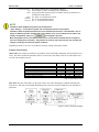
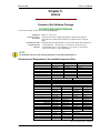
The following files and sub directories will be found in the main program menu directory:
Files
ALARMS\
DL\
LNG\
PICTURES\
STD\
TOOLS\
System files “*.*”, configuration files “*.cfg”, event memory files “*.dat”,
and files for external tools.
For daily alarm protocols “01.alm” to “31.alm”
For temporary data-logging files “DLx.tmp”, where x stands for the device
number
For the load language files “*.lng”
For the bit map layout files “*.bmp”
For the standard value files “*.std”
For the assembler “*.asm” and option files “*.opt” used with the configuration files
NOTE
Temporary files are created for each connected, device that are used to display the configured values
after exiting or in the event of an application crash for restarting the LeoPC1. These files are lost when
a new configuration is started.
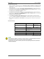
LeoPC1 can be installed on all Microsoft Windows©-systems. When installing LeoPC1 the following requirements must be followed:
WinNT/2000/XP
Administration rights for the computer to have the program installed. The
operator for the program will require main user rights to the computer at a
minimum.
The required hard drive space for installing LeoPC1 is dependent on the application modules of the version to be
installed:
The program will require between 20 and 60 MB of storage space.
NOTE
These specifications are minimum specifications and relate to the LeoPC1 itself.
This specification does not account for storage space that will be required by the configuration, data
logging, alarm management files and all other files created for the use of this software tool.
Procedure for Installation
NOTE
The beginning of the software installation is dependent upon the source for the LeoPC1 program. If a
dialog window does not initiate from the installation program, follow the instructions below.
Ensure that all setup files are in one directory prior to starting installation.
The number of files that must be located depends on the version of LeoPC1. The following files must
be located:
• LeoPC1.exe
or:
• Install.ini, ReadMe.txt
• Setup.exe and other Setup.W0n (‚n’ stands for numbers from 2 to 4)
• Package1.exe and may be other package files
• Vci2.xx.exe (‚xx’ stands for the current version of the IXXAT driver).
Page 10/91
© Woodward
Manual 37146B
LeoPC1 - User Manual
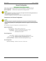
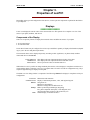
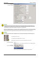
To start installation:
or
and
Insert the CD-ROM into the CD-Rom drive
Locate and (double) click on: Setup.exe
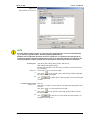
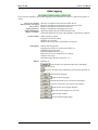
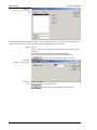
Click on the Start button for Windows
Move the cursor up to Run and click on it (the Run dialog is opened)
Enter “PATH\Setup.exe” (“PATH” stands for the drive to be used)
Figure 2.1
Start installation
or
Search... (Setup.exe in the corresponding installation directory)
OK
NOTE
The installation is initiated by setup.exe or LeoPC1.exe depending on the version of the software.
Continue with the installation by following the prompts and instructions given in the dialog windows.
There may be differences in the dialog windows that are dependent upon the software version being
installed.
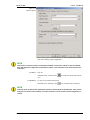
The following dialog windows will guide you through the setup procedure. By clicking on the “Next” button, the
program will advance to the next dialog window. It is strongly recommended to read all of the dialog windows
when performing the installation. If any it is desired to make changes to the setup, it is possible to return to all
previously displayed screen by clicking on the “Back” button.
-
Welcome (greeting and notices)
ReadMe file (important installation information)
Choose destination location (please select your directory here)
To select a directory:
or
C:\Program File\Woodward\LeoPC1 (represents the standard setting, where
the main directory of the LeoPC1 will be installed)
Select your desired path or directory
NOTE
You may install LeoPC1 to any desired location in your computer with the “Choose Destination Location” dialog window. It is recommended to utilize the default location. All sub-directories of LeoPC1
will be installed in the directory selected during this step.
After LeoPC1 has been installed on the computer do not alter or move individual software tool components or entire directories. Doing so may result in errors or the program failing to operate properly.
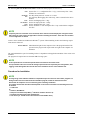
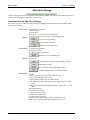
Select components
© Woodward
(uncheck the non-required components)
Page 11/91
Manual 37146B
LeoPC1 - User Manual
Figure 2.2
Select components
NOTE
If required, any components that were not installed in the initial installation may be installed at a later
date by simply repeating the installation procedure and selecting the desired components to be installed.
If another CAN driver is installed on your system, a notice will be displayed. It is possible to continue
the setup and use the old driver version with limited compatibility for the latest CAN-Interfaces.
The recommended to de-install the old configuration and driver of your CAN bus Interfaces according
to the instructions of IXXAT http://www.ixxat.de before starting the setup program. New CAN bus drivers will be installed by the setup.
After LeoPC1 has completed its installation procedure, the option to install the IXXAT-VCI-driver on the
PC/laptop will be given.
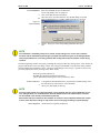
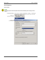
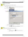
Select language
(Select the language with which the LeoPC1 is to be started initially after
the installation)
Figure 2.3
Select language
Start installation
File installing
Plant configuration
Page 12/91
To start installation, click the “Next” button.
A progress bar will be displayed while the file is installing
Please wait... (interim information)
© Woodward
Manual 37146B
LeoPC1 - User Manual
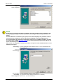
Setup – IXXAT VCI V2.16 for
Windows ...
The VCI driver for IXXAT CAN-Interfaces may now be installed. If this
message is not displayed, the appropriate drivers are already installed or the
VCI version 1 is already installed.
Finish installation
Click the
button to complete the installation.
Figure 2.4
Finish installation
NOTE
It is necessary to restart the PC/laptop after the completion of the installation to ensure the operating
software is stored and all functions and links are properly enabled.
After rebooting the PC/laptop, LeoPC1 may be started by following the log on procedure below:
To start the application:
or
or
© Woodward
Click on:
Start..Programs..Woodward.. LeoPC1.. LeoPC1
Via Windows-Explorer start the “main.exe” in the selected main directory
Start a “*.cfg” file in the selected main directory
Page 13/91
Manual 37146B
LeoPC1 - User Manual
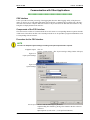
To log on: Click on:
System...User Login or click the
icon.
Figure 2.5
Open User Login
In the “Name” box type the user name as “system”.
In the “Password” box type in the password as “system”
(to protect the password letters are displayed as ****).
Figure 2.6
User Login
Click
to gain access.
NOTE
It is recommended that the system administrator change the password immediately after logging on
the first time. Make note of the password issued to you, as most functions of LeoPC1 require this
password for access.
If you attempt to utilize LeoPC1 prior to logging on, you will be prompted that logging on is required.
By clicking on the “Yes” button the User Login dialog window will be displayed.
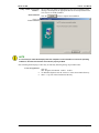
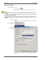
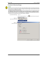
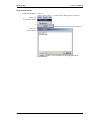
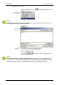
Defining the system After logging in to LeoPC1, click on:
administrator:
System...User management... (the Users Management dialog window will
appear)
Figure 2.7
Open User Management
Editing boxes
and
and
At the bottom of the dialog window is the “New user” box. Type in the desired user ID
Type the desired password into the “Password” box
Type the desired password again into the “Repeat” box
To enable the new user ID and password click on
Page 14/91
.
© Woodward
Manual 37146B
LeoPC1 - User Manual
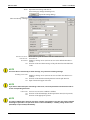
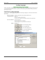
Option:
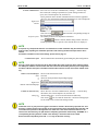
Setting the level of access for users: by clicking and highlighting a user ID
the level of access may be changed. The default level of access is Level 1
authorized. Click on the desired access level and enable it by clicking
.
Deleting a user ID: By clicking on a user ID and highlighting it then clicking the “Delete” button a user ID is deleted from the Users Manager. Before
deleting the default user ID and password system, it is strongly recommended that the new system administrator log off and back on to verify that
the new ID and password function properly. After this has been verified, delete the default user ID “system” and password for security purposes. It is
required to click
window.
to enable any changes made in this dialog
Figure 2.8
User Management
© Woodward
Page 15/91
Manual 37146B
LeoPC1 - User Manual
Procedure for De-installing
During installation of the LeoPC1, a tool is also set up for de-installing this program. If you wish to remove
LeoPC1 version on your PC, please use this tool only.
To start uninstalling:
or
or
The pathway to unwise.exe if the default installation was utilized is typically
C:\Program Files\Woodward\LeoPC1\unwise.exe.
(Double) click on: Unwise.exe
Start\Run\unwise.exe
Search\unwise.exe
NOTE
Please continue to follow the directions of the de-installer program, which will guide you through the
Unwise dialogs, if you confirm with
. When the de-installer program, Unwise.exe, has
been started, you will be prompted to make decisions on the de-installation process. Confirm your
choices by clicking on the “Next” button.
For easy and quick uninstalling, use the option “Automatic” and confirm by clicking on “Next”.
The option “Custom” requires extensive administrative knowledge and is not covered by this manual.
If the application is to be de-installed and the configuration files (*.cfg and *.asm) or other files generated during use of the application need to be kept, the configuration files will need to be copied to another directory prior to uninstalling the application. If the application is uninstalled prior to transferring
these files, they may no longer be available after de-installing.
Generally the file folder for LeoPC1 and individual files stored in it are not affected by the deinstallation. The file folder may be deleted by following the directions below if the default installation
was chosen.
To delete main directory:
and
and
Page 16/91
Click on:
My Computer... Program Files... Woodward...
Highlight the LeoPC1 file folder
Delete the file folder
© Woodward
Manual 37146B
LeoPC1 - User Manual
Loading a Plant Configuration
≡≡≡≡≡≡≡≡≡≡≡≡≡≡≡≡≡≡≡≡≡≡≡≡≡
NOTE
Open your plant configuration from the actual application.
A plant configuration must be opened from the correct application file (**.asm). LeoPC1 must be
started and the correct application file opened to begin configuring a plant.
Various plant configurations can be loaded with LeoPC1. The plant configuration functions and layout are dependent on the following::
Version of the LeoPC1 being used
Devices that are to be communicated with
Tasks that to be assigned to devices
Requirements that the plant must meet
Basically it can be differentiated between:
•
•
•
•
Demo configuration
Direct parametric configuration
Display configuration
Configuration and display configuration
NOTE
Due to the numerous control units and possible combinations of these units, it is impossible to cover
every plant configuration. Operator control will be discussed only in general terms because of this.
For further information on and examples of configurations, please refer to the following sections:
Fehler! Verweisquelle konnte nicht gefunden werden.“General Configuration” after page 22
”Communication and Connection” after page 69
and the corresponding sections of the manuals for your specific control unit
Some prerequisites have to be met before you can load your plant configuration (provided that it has not been
done already by installation)
To copy files:
Pathway
and
Pathway
Use, for example, Windows-Explorer for this step:
Copy the corresponding CFG configuration file (*.cfg) to the main menu in
the LeoPC1 file folder
C:\Program Files\Woodward\LeoPC1
Copy the pertinent ASM configuration file (*.asm, if necessary *.opt) to the
sub-directory TOOLS in the LeoPC1 file folder
C:\Program\Woodward\LeoPC1\Tools
Copy and paste.
NOTE
In some versions of LeoPC1 (e.g. LeoPC1.cfg), it is possible to copy and paste configuration files from
a floppy disk or a CD-ROM. If too many sub-directories are transferred at one time by this method, the
possibility of errors occurring in the files is greatly increased.
© Woodward
Page 17/91
Manual 37146B
LeoPC1 - User Manual
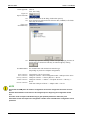
To use copy tools:
Click on
Tool...Get Config
Figure 2.9
Open Tools menu
and
and
Follow the directions in the dialog window that opens up
Select the desired configuration files from the disk, CD ROM, or file folder
where they are located.
Figure 2.10
Search directory
and
Start the copy operation. A dialog window will open displaying the status of
the files that were transferred. This may be acknowledged by clicking
.
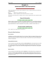
To connect devices
For communication with the desired connection type
(Depending on your device and plant configuration):
Demo connection
Direct connection
Gateway connection
Modem connection
Connection to a device is necessary
COM port of the PC > Direct configuration cable > RJ45 port of the device
COM port of the PC <> Gateway RS-232 <> Device.
COM port of the PC <> modem <> Telephone network <> Gateway <>
Device
CAN card COM port of the PC <> Adapter cable <> Device
CAN bus connection
NOTE
Ensure that the COM port to be used for configuration has not been assigned to more than one function.
Read the documentation of the device to be configured prior to beginning the configuration of that
unit.
All control units will require individual tuning to gain optimum performance within the plant.
Some older control units require the configuration interface to be activated before configuration can be
performed.
Page 18/91
© Woodward
Manual 37146B
LeoPC1 - User Manual
To activate devices:
Configuration method
Direct connection
Gateway and modem connection
CAN bus connection
To load a configuration:
and
or
Configuration method
Direct connection
Gateway, modem or
CAN bus connection
To log on:
Turn power on to all devices to be configured.
On devices with a display set the direct configuration screen to “ON”
On devices with display set the direct configuration screen to “OFF”
(the CAN bus interface is disabled when the direct configuration mode is
enabled)
On devices with displays set the direct configuration screen to “OFF”
(the CAN bus interface is disabled when the direct configuration mode is
enabled)
Click on:
Start...Program...Woodward...LeoPC1...LeoPC1 (application is started)
File...Open…(the “Open” file dialog window is opened)
icon.
Or click the
Select the *.cfg file that has been copied to the main directory
Start the *.cfg file directly from the selected mains directory
Only used for configuration of the device. Display of the measured data may
not be possible.
The device may be configured while measured data from the generator/
plant is displayed. Extreme caution must be exercised when configuring
through this method.
Click on:
System...User Login...(Only personnel with system administrator privileges
may configure control units)
Or click the
icon.
NOTE
If no changes have been made to the user/password settings, the user ID and password for the system
administrator will still be set as the default:
Name = “system”
Password = “system”
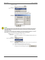
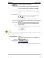
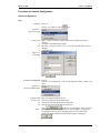
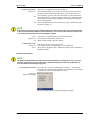
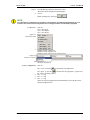
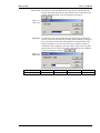
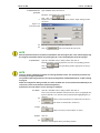
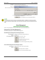
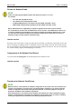
To select application modules:
Click on:
Devices...Settings... (Settings to parameterize system dialog window will
open)
Figure 2.11
Open Device Settings
Select Enable Program Modules (changes the available configuration modules)
© Woodward
Page 19/91
Manual 37146B
LeoPC1 - User Manual
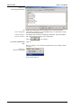
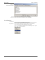
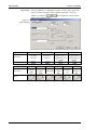
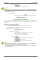
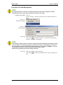
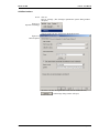
Figure 2.12
Enable Program Modules
and
Direct configuration
Gateway, modem or
CAN bus connection
Enable the modules that will be required for the connection and tasks:
The modules “Parameterize” and “standard values” are sufficient to configure most control units generally.
All modules may be used for configuring control units. Select the modules
that will be needed according to your requirements
Click on
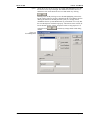
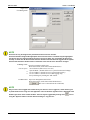
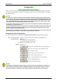
To select the communication
type:
to save settings.
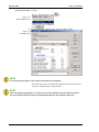
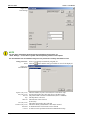
Click on:
Devices...Settings... (The “Settings to parameterize system” dialog window
will open)
Figure 2.13
Open Device Settings
Select General Options
Page 20/91
© Woodward
Manual 37146B
LeoPC1 - User Manual
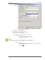
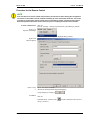
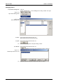
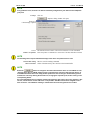
Figure 2.14
General Options
and
Direct configuration
Gateway connection
modem connection
CAN bus connection
Remote control
Displays
or
Select the method of configuration to be used in the Data communication
Driver box from the following:
Driver: “Direct”
Driver: “Gateway RS-232”
Driver: “Modem”
Driver: “IXXAT VCI2 – CAN”
Set the remaining dialog boxes as follows:
“Not active”
“Deactivate while parameterizing/load language”
Set according to requirements
NOTE
Refer to the product manual when selecting the baud rate for communications.
To connect:
Click on:
Communication...Connect (The communication link between the PC/laptop
and the device is established)
Or click the
© Woodward
icon.
Page 21/91
Manual 37146B
LeoPC1 - User Manual
General Configuration
≡≡≡≡≡≡≡≡≡≡≡≡≡≡≡≡≡≡≡≡≡≡≡≡≡
LeoPC1 may be configured in several different ways. For this purpose it is differentiated between:
General configuration Adaptation of the system settings and the device settings to your plant
Special configuration
Creation of the *.cfg files and *.asm configuration files
NOTE
Special configuration is generally not necessary. Your supplier should have already performed all necessary adaptations to your plant and devices.
This special configuration is described in more detail in a separate manual 37164.
Components of the General Configuration
NOTE
Ensure that the general configuration described below can only be accessed/performed by experienced personnel through the use of the System administrator. Failure to do so may result in these settings will interfering with your PC operating system, the hardware configurations, and/or the plant configuration.
The components of the general configuration are subdivided into three areas:
System Configurations
Log on /log off user
User management
System settings
Dialog window for logging on/off
List of the user names, passwords, and access rights
Language settings and logging parameters
Path variables for CFG-files
Plant Configurations
General options
and
Service Configuration
Enable program modules
Definition of the alarm path and of the alarm help file
definition of the data communication and connection settings
Definition of parameters for the data buffer etc.
Definition of the enable/disabled application modules
View Configurations
Symbol bars and settings
Page 22/91
Definition of the LeoPC1 window layout
© Woodward
Manual 37146B
LeoPC1 - User Manual
Procedure for General Configuration
System Configurations
User
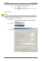
To log on:
Click on:
System...User Login or click the
icon.
Figure 2.15
Open User Login
Editing boxes
or
and
or
Name: “system” (visible as system), if the factory default has not been
changed
“User ID” (with administrative rights)
Password: “system” (visible as ******), if the factory default has not been
changed
“User password”
Figure 2.16
User Login
Click
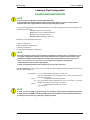
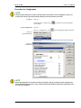
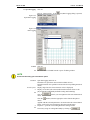
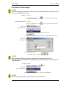
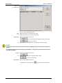
To open user management Click on:
System...User management... (The user management dialog window will
open)
Figure 2.17
Open User Management
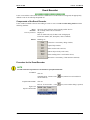
To set up a user Open user management and click on:
Editing boxes: “New user” and enter the desired user ID
and “Password” and enter the desired user password
and “Repeat” and verify the desired user password
Option:
© Woodward
Click
and the new user will appear in the Users List
Highlight the desired user ID and click on ”System admin.” to assign full
access rights to this user or the appropriate level of access at this time.
Confirm all changes made to users and access rights by clicking on
Page 23/91
Manual 37146B
LeoPC1 - User Manual
Figure 2.18
User Management
NOTE
A user ID can only be assigned one password and level of access at a time.
A user ID should be assigned the appropriate level of access when it is created. Only the highlighted
user ID can have any changes made to the level of access or status. It is not possible to edit a password for an active user ID. A user ID that has been deleted cannot be edited or logged onto the system.
User ID’s that have been deleted can be re-entered as a new user ID if it is desired to use again.
To manage a user: Open Users manager and click on:
Desired options:
or
or
To delete a user
Desired user name (scroll menu with all defined users)
“Access denied” (denies access to a user)
“System admin.” (Permits full access to system functions and settings)
“Level 2 authoriz.” (Permits access to system functions only)
“Level 1 authoriz.” (Permits access to data logging only)
Verify all changes by clicking the “OK” button.
Open user management and click on:
Desired user name (scroll menu with all defined users)
(The user is removed from the scroll menu)
NOTE
Only one user can be logged onto LeoPC1 at any one time. If a user is logged on, he/she must log off
to permit another user to log on to the application. The user ID of the signed on user is displayed at the
bottom right corner of the LeoPC1 window. The user may be logged off by clicking on the
using the “System” button in the tool bar and clicking on “Log off user”
Page 24/91
icon or
© Woodward
Manual 37146B
LeoPC1 - User Manual
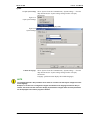
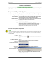
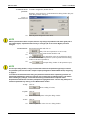
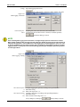
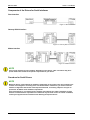
System
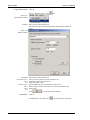
To open system settings
Select “System” from the Command menu, “System Settings…” from the
drop down menu (the “System settings” dialog window will open),
and click on:
Figure 2.19
Open System Settings
Settings tab (changes the displayed tab)
Figure 2.20
System Settings
To define the language
Select “System” from the Command menu, “System Settings…” from the
drop down menu (the “System settings” dialog window will open),
and click on:
Language: (pull down menu displays all available languages)
NOTE
The language defined in this parameter has no effect on a control unit that may be configured in a different language.
Example: If a control unit is configured in English and German is the language selected for this parameter, the control unit will continue to display all parameters in English while the same parameters
will be displayed in the LeoPC1 program in German.
© Woodward
Page 25/91
Manual 37146B
LeoPC1 - User Manual
To define data logging:
activate
deactivate
Saving data
Select “System” from the Command menu, “System Settings…” from the
drop down menu (the “System settings” dialog window will open),
and click on:
Start data logging automatically upon loading the plant configuration
Save data logging automatically upon closing the plant configuration
Enter a check mark in the box next to the desired data logging option
Remove the check mark in the box next to the data logging option to be deactivated
Click on the
icon to open the “Save As“ dialog window, type in the
name of the file for the data, and select the file to save the data in. After a
file name has been selected the Save button has been clicked, the pathway
for the file will be displayed in text box. The OK at the bottom of the System settings dialog window must be clicked to accept any changes made to
these settings.
NOTE
When saving data logging files, they must end in ".llo". All data logging files must use the "LLO" format.
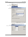
To define data export:
To open system settings
Select “System” from the Command menu, “System Settings…” from the
drop down menu (the “System settings” dialog window will open),
and click on:
Under “setting for export data logging files” enter a check mark in the box
next to “Output header line?”
Enter separator character (it is recommended that a semicolon “;” be used).
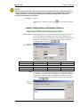
Select “System” from the Command menu, “System Settings…” from the
drop down menu (the “System settings” dialog window will open),
and click on:
Figure 2.21
Open System Settings
Paths tab (changes the displayed tab)
Page 26/91
© Woodward
Manual 37146B
LeoPC1 - User Manual
Figure 2.22
Path variables for CFG files
NOTE
As newly defined variables require an equivalent in the configuration file, it is not recommended adding or removing any path variables, but merely adapting the directories.
Example: If the configuration files were stored in a common file on a network so that they may be accessed from multiple computers instead of being stored on an individual computer, the pathway to the
necessary CFG files would be modified here for the computer that will require access to these files.
To define paths:
Editing box
or
Open the System settings dialog window and click on:
Paths (changes the displayed page)
Desired path variable for CFG file (selected variable is entered into the text
box for editing)
In the “Path:” text box enter desired path
Click on the
icon to open the “'Select Path” dialog window and modify
the pathway to the desired path
and
Click
variable)
To define the path variable
Editing boxes:
or
to enable the new path (the path is relocated to the path
Click on:
Click in the “Variable:” text box and enter the appropriate designation of the
CFG file
Click in the “Path:” text box and enter desired path
Click on the
icon to open the “Select Path” dialog window and enter
the desired path
and
Click
to enter the new path variable (the path variable is set
and appears in the list box)
© Woodward
Page 27/91
Manual 37146B
LeoPC1 - User Manual
Plant Configurations
General settings
NOTE
Any changes made to the General Options will take effect immediately after the dialog window is
closed.
To open general settings
Select “Devices” from the Command menu, “Settings…” from the drop
down menu (the “Settings to parameterize system” widow will open):
Figure 2.23
Open Device Settings
Figure 2.24
General Options
Page 28/91
© Woodward
Manual 37146B
LeoPC1 - User Manual
To define communication: Select “Devices” from the Command menu, “Settings…” from the drop
down menu (the “Settings to parameterize system” dialog window will
open), the “General Options” tab, and click on:
Driver pull down menu: in Data communication and select the applicable
driver for your configuration method (all installed drivers will be displayed)
Figure 2.25
Drivers
Requisite options:
Next click on the
button and the corresponding settings for
the selected driver are displayed.
The tunable parameters are dependent on the driver
If the
button is clicked, another dialog window with more
tunable parameters that are specific to the selected driver are displayed.
NOTE
If required, any components that were not installed in the initial installation may be installed at a later
date by simply repeating the installation procedure and selecting the desired components to be installed.
For further information on the exact settings, please refer to page 10.
Communication option
“Start communication automatically upon loading the plant configuration”
NOTE
Placing a check mark in the box next to the text enables this option. If this has been enabled, LeoPC1
will attempt to establish communication with the control unit immediately after the plant configuration
has been loaded. If this option is disabled communication with the control unit must be started manually.
Remote control and Displays
Mode
or
or
Select a mode from the list below:
activated
deactivate while parameterizing/loading language
not activated
Figure 2.26
Remote control and Displays
To define the alarm directory
Editing box:
or
Select “Devices” from the Command menu, “Settings…” from the drop
down menu, the “General Options” tab, and click on:
“Path for alarm files:”: text box and enter the desired directory
Click on the
icon for “Path for alarm files:” and click on the appropriate file folders in the ”Select Path” dialog window.
NOTE
Faults that occur on your plant are logged in files that are stored in the directory specified here. This
directory is always relative to the position of the corresponding plant configuration file (CFG file) and
not relative to the position of the application file “Main.exe”. This means that if the CFG file is not
stored in the main directory, the path must be completely specified for the directory “ALARMS\” or a
corresponding directory must be created in the directory in which the CFG file is located.
Ensure that the new pathway ends with ”\” or it may not function correctly.
© Woodward
Page 29/91
Manual 37146B
LeoPC1 - User Manual
To define the alarm help file
Editing box
or
Select “Devices” from the Command menu, “Settings…” from the drop
down menu, the “General Options” tab, and click on:
“Help file for alarms:”: and enter data path
Click on the
icon for “Help file for alarms:” and click on the appropriate file folders in the ”Open” dialog window.
Service Configuration
NOTE
The settings on this tab page should only be changed by experienced users or by your support team.
Under certain circumstances the application will no longer process all data if the wrong parameters are
entered here. Any changes made to this tab page do not become active until the application has been
restarted or the plant configuration has been reloaded.
To open device settings
Select “Devices” from the Command menu, “Settings…” from the drop
down menu (the “Settings to parameterize system” dialog window will
open) and click on:
Figure 2.27
Open Device Settings
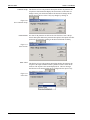
Service Configuration tab (changes the displayed tab page)
Figure 2.28
Service Configuration
Page 30/91
© Woodward
Manual 37146B
LeoPC1 - User Manual
To define the data buffer:
Editing boxes:
and
and
Open Service Configuration tab page and click on:
“Size of the data buffer” text box (The entered value must be greater than
the highest parameter-ID and greater than the “ID of the first entry for remote monitoring” plus the ”Size of the data buffer for remote monitoring”)
”ID of the first entry for remote monitoring” (The entry is dependent on the
device and must be larger than the highest parameterization ID, all higher
values will be ignored).
“Size of the data buffer for remote monitoring” (Entry is the number of display data words plus 1).
NOTE
Some older control units may have different default values than newer control units of the same model
in the text field “Size of the buffer for remote monitoring”. If an incorrect value has been entered, some
or all of the monitored values will not be displayed or logged!
Option:
Editing boxes:
and
To define Windows title:
Editing box:
Option:
“Test mode” (if enabled, default values are read and saved)
”ID for remote control word” (default is 503)
“Break for data transfer” (default is 200 ms)
Open Service setting tab page and click on:
”Text within title row” (your desired title can be edited here)
”Show name of program as title?” (Enables the display of the custom title by
checking the block)
Enable program modules
NOTE
The Enable Program Modules tab page specifies which modules are available for the user. Only modules with check marks in the box next to it are enabled and displayed in black text. All Modules that
have been disabled are displayed in grey text.
To select application modules:
Select “Devices” from the Command Menu, “Settings…” from the drop
down menu, the “Enable Program Modules” tab, and click on: (the “Settings
to parameterize system” dialog window will open)
Figure 2.29
Open Device Settings
Enable Program Modules tab (changes the displayed tab page)
© Woodward
Page 31/91
Manual 37146B
LeoPC1 - User Manual
Figure 2.30
Enable Program Modules
to activate
to deactivate
Insert a check mark inside the box next to the Module
Remove the check mark from the box next to the Module
View Configurations
To select view:
On possible bars:
Page 32/91
Select View from the Command Menu and enable the desired selection by
placing a check mark next to the desired View tool:
View...Tool Bar (enables quick operator control via screen buttons)
View...Status Listing (supplies information to the operator)
View...Levels (enables fast changing between monitoring levels (i.e. power
plant, engine, or sensors/actuators)
© Woodward
Manual 37146B
LeoPC1 - User Manual
Dynamic Configuration
≡≡≡≡≡≡≡≡≡≡≡≡≡≡≡≡≡≡≡≡≡≡≡≡≡
Using the dynamic configuration module, LeoPC1 creates the parameter lists and display levels according to the
options selected.
Components of the Dynamic Configuration
The components of the dynamic configuration are not immediately recognizable. If this type of configuration is
utilized, the components of the dynamic configuration are hidden in the device and relevant files (*.cfg, *.opt and
*.asm) for the configuration of the plant .The components can be subdivided as follows:
Device parameters:
Language parameters:
Button:
Files:
The corresponding values are tunable for the individual control unit and determine the parameter list for the individual application modules.
The corresponding values from the system data of the application determine
the language for the display of your measured values.
Performed via:
Devices...Refresh Configuration
OPT files contain definitions for the dynamic configuration.
ASM files contain options for the specific control unit and are the tool files
required for the CFG file to communicate with the LeoPC1 program.
CFG files contain options for the specific control unit and reflect any
changes that have been made to parameters in the control unit.
Procedure for Dynamic Configuration
NOTE
Devices with the option of dynamic configuration usually only require this once during the setup of the
control unit. Dynamic configuration will not work if the control unit is not connected to the PC/laptop
running LeoPC1.
To connect:
Click on:
Communication...Connect or
made)
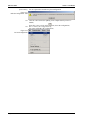
To configure dynamically:
icon (connection to the selected device is
Click on:
Devices...Refresh configuration (starts the dynamic configuration)
Figure 2.31
Open Refresh Configuration
Question dialog
"Are you certain that you want to refresh dynamic configuration?"
Figure 2.32
Refresh Configuration - Start
and
© Woodward
Click the “Yes” button (a status dialog window "Parameter data for dyn.
configuration" appears briefly)
Page 33/91
Manual 37146B
LeoPC1 - User Manual
Question dialog
You are requested to load the new plant configuration.
Figure 2.33
Refresh Configuration - End
and
and
Click the “OK” button (the updating is not completed until you have reloaded)
Select File...New or click on the
icon (closes the configuration)
File...1 Name of the configuration.cfg
(Re-opens and updates the configuration)
Figure 2.34
Re-load configuration
Page 34/91
© Woodward
Manual 37146B
LeoPC1 - User Manual
Chapter 3.
Properties of LeoPC1
Depending on the type and configuration of the devices, LeoPC1 puts the components explained in detail below
at your disposal.
Displays
≡≡≡≡≡≡≡≡≡≡≡≡≡≡≡≡
LeoPC1 can display the current values of the connected devices. This permits for a complete overview of the
status of your plant, machines, and devices.
Components of the Display
There are two primary formats to display the measured values and different statuses of your plant
• In a bit map format
• In a tabular format
In turn these formats may be configured in various ways and differ in quantity of displayed information (depending on you’re the user and plant requirements).
The measured values can be displayed separately according to their significance, on plant-related, machinerelated and device-related levels:
Power plant level:
Machine level:
Sensors/actors:
This displays the most important monitored values of the plant.
This displays the most important monitored machine values.
These represent all values of monitored devices.
Within these levels it is possible to change randomly between the various displays in compliance with the user’s
needs and thus obtain a complete overview of your plant status. If LeoPC1 is used for configuration only, only a
simple background image is displayed of the plant.
The Plant overview dialog window is composed of the following elements for displays in compliance with your
configuration:
Text boxes:
Parameter boxes:
Buttons:
Bitmap:
Table:
© Woodward
Information and comments
Display of monitored parameter, value, and engineering unit
Navigation via:
Buttons for alarm display
Buttons to change between different levels
Makes up the background design, integrating
title, plant component descriptors, circuit diagrams, and
open/closed breaker positions of the generator(s) etc.
Tabular display of monitored values
Page 35/91
Manual 37146B
LeoPC1 - User Manual
Procedure for Displays
To load configuration:
and
Click on:
File...Open... or the
icon
Select the appropriate *.cfg file from the ”Open” file dialog window
NOTE
It is possible to open a *.cfg file by locating it through Windows-Explorer and double clicking on the
desired file.
The control unit cannot be configured or updated unless communication between the control unit and
the PC/laptop has been established.
If a *.cfg file is opened without a having an automatic connection established, the default values are
displayed. If the connection is interrupted after a data transfer, the last values displayed will remain on
the screen.
To set displays:
Click on:
Devices...Settings... (The “Settings to parameterize system” dialog window
will open)
Figure 3.1
Open Device Settings
General Options tab (changes the tab page displayed)
Figure 3.2
General Options
Put a check mark in the box next to “Start communication automatically
upon loading the system configuration ” to enable automatic communication.
Page 36/91
© Woodward
Manual 37146B
LeoPC1 - User Manual
Displays
or
From the Displays pull down menu select either
”Deactivate while configuration/load language”
'”active”
Enable all changes by clicking on
.
NOTE
The next time this configuration is opened the communication is established automatically. If a connection to the control unit currently exists, all the configured values are immediately displayed.
To select view:
Click on:
View...Next View
View...Next Engine
View...Next Device
Figure 3.3
Open View menu
or
Pull down menu of plant level
Pull down menu of engine level
Pull down menu of device level (sensors/actors)
Figure 3.4
Select View Levels
and
To close a configuration:
Select the desired level
Click on:
File...Close or click the
or
or
or
© Woodward
icon (terminates your application)
File...Open...or click the
icon and select the appropriate *.cfg file from
the ”Open” file dialog window
File...1 **.cfg
File...2 **.cfg
File...3 **.cfg
Opens the selected configuration and simultaneously closes the previously
opened configuration file
Page 37/91
Manual 37146B
LeoPC1 - User Manual
Configuration
≡≡≡≡≡≡≡≡≡≡≡≡≡≡≡≡≡≡≡≡≡≡≡≡≡
LeoPC1 can provide user support for the configuration of a control unit. This program permits a control unit to
be set up for a new application or adapted for new requirements to an existing system within the control unit’s
individual parameters.
NOTE
In some cases it may be necessary to see the parameter list without displaying any configured values
of a control unit. This can be accomplished by selecting “Devices” from the Command Menu and “Settings...” from the drop down menu. Click on the “Service Configuration” tab to display the tab page. Insert a check mark in the box to the right of the text “Test modus (set data with default values)”. Verify
any changes made to the tab page by clicking the “OK” button.
This function enables the user to configure, print, and/or save parameter lists without affecting any selected drivers or connected devices.
Do not use STD files that have been created in the Test modus to configure any control units. Some parameters will not load correctly unless the control unit is running and communicating with LeoPC1
when the change to the parameter is made.
Ensure that the “Test modus” is disabled after it is no longer required. Failure to do so will result in the
user not being able to configure control units until this function is disabled.
Components of the Configuration
For online configuration LeoPC1 provides a configuration dialog window with the following functions:
Device to be parameterized:
Relevant parameter:
and
Buttons:
Selection via the pull down menu with all corresponding devices
Display of:
Name (designation of the parameter)
Value (value last read of the parameter)
Rights (read = 'R' and/or write = 'W')
Handling via:
(By this means you change and transfer the parameters)
(Reads one or more current values from the device)
(Aborts reading of values)
(Reads all current values from the device)
(Prints out the current parameter list)
(Saves the current parameter list as an STD file)
(Calls corresponding help file)
(Closes the configuration dialog)
NOTE
It is possible to parameterize multiple units by saving the control unit configuration as an STD file. If
the user desires to transfer the same configuration settings to a second control unit, this is accomplished by utilizing the “Standard Values” dialog window (see "Standard Values" after page 45).
Page 38/91
© Woodward
Manual 37146B
LeoPC1 - User Manual
Procedure for Configuration
NOTE
Communication between the control unit and LeoPC1 must exist for online configuration. If this connection does not exist, you will be asked whether you wish to start this connection.
To connect:
Click on:
Communication...Connect or the
vice is made)
To open configuration:
icon (connection to the selected de-
Click on:
Devices...Configuration...or the
icon (Configuration dialog is opened)
Figure 3.5
Open Parameterize
Select the desired control unit using the pull down menu with all available
devices listed
Figure 3.6
Parameterize
NOTE
Before the parameters for a control unit may be changed, it may be necessary to enter a password in
the Parameterize dialog window. If this is required follow the operating instructions that pertain to the
device being configured.
© Woodward
Page 39/91
Manual 37146B
LeoPC1 - User Manual
To unlock the device
protection:
To enable configuration, double click on:
Parameter ”password level 2” in the Parameterize dialog window (the password dialog window will open)
Figure 3.7
Enter Password
and
Enter the password specific to the device
NOTE
After the password has been accepted, the user may change all parameters with write rights ("W" in
the column Rights). A parameter that has only a read right ("R" in the column Rights) cannot be
changed.
Parameterization:
or
and
or
Open Parameterization and click on:
(Only if all current parameters are to be read)
Highlight one or more parameter that should be read
Click
(the marked line values are read from the device)
Double click on the desired parameter (scroll in parameterization dialog
window to the desired parameter)
and
Click
(an input dialog window for the parameter open)
NOTE
For the input dialog window, a range of values that conform to the parameter type may be entered.
The possible inputs can be found in chapter "Inputs (Configuration and Standard Values)" beginning
on page 41.
In contrast to the standard values dialog, the parameters entered via the input dialog windows are
transferred immediately to the device when the user confirms the input dialog with the ”Ok” button.
Prior to making any changes, ensure that values being transferred are the required values.
All parameters that failed to read when prompted are highlighted in blue. The user may attempt to reread these parameters by clicking on the “Marked Rows” button.
To stop:
Click on:
(Aborts reading of values)
To print:
and
To save:
and
Page 40/91
Click on:
Select the desired options in the print dialog window
Click on:
Create or update file in the “Save As” dialog window
© Woodward
Manual 37146B
LeoPC1 - User Manual
NOTE
The file name must end with ".std" and the file must have the STD format. The current settings will be
saved in STD format in the file specified by the user. The STD file may be modified offline without an
existing connection or for archiving as standard values that may be transferred to a control unit
through the Standard Values procedure.
To disconnect:
Click on:
Communication...Interrupt or click on the
tion)
icon (terminates the connec-
Inputs (Configuration and Standard Values)
≡≡≡≡≡≡≡≡≡≡≡≡≡≡≡≡≡≡≡≡≡≡≡≡≡≡≡≡≡≡≡≡≡≡
Enter A Number
Enter the numerical value for a parameter in the input range. The first line of
text for the window is the parameter description. The second line is a generic screen definition for the control unit. The third line is the input field in
that the user can change the value. The last line is the input range. Verify
.
any changes made by clicking on
Figure 3.8
Enter A Number
Real power set value
Input
Cosine-Phi
Input
Flags
Outgoing power
E0000 to 6900
Fixed value power
C0000 to 6900
Reference power
I0000 to 6900
Capacitive/Lagging
k0.01 to 0.99
1.00
Inductive/Leading
i0.01 to 0.99
The first line of text is the parameter description. The input field contains up
to a maximum of 16 discrete inputs, which may be enabled (E) or disabled
(D). In order to change the state, check marks must be added or removed
from the boxes to the left of the discrete input. Verify any changes made by
clicking on
.
Figure 3.9
Set Flags
© Woodward
Page 41/91
Manual 37146B
LeoPC1 - User Manual
Connector Group
The first line of text is the parameter description. Below the parameter description are four buttons that display the current status of the button. To
change a status, press the desired button. The button will change the displayed status to the next value. Verify any changes by clicking on
.
Figure 3.10
Set a Connector Group
Insert YES/NO
Set value of the parameter on YES or NO. The first line of text is the parameter description. Below the parameter description is the option field. The
option may be changed by clicking on the desired field and verified by
clicking on
.
Figure 3.11
Insert Yes/No
Select A Text
The first line of text is the parameter description. Below the parameter description is the input field that contains a pull down menu to select the desired text. The top line is the current displayed text. The text messages
listed below are the messages that may be configured to the input. Verify
any changes by clicking on
.
Figure 3.12
Select Text
Page 42/91
© Woodward
Manual 37146B
LeoPC1 - User Manual
Insert A Text
The first line of text is the parameter description. Below the parameter description is the input field. The user may define the text of a parameter up to
16 digits in the input field. Verify any changes by clicking on
.
Figure 3.13
Insert Text
Input Relay
The first line of text is the parameter description. Below the parameter description is the input field. The relay manager function linking is configured
here. The numeric codes for the desired functions are linked with the logic
symbols listed below. Up to three functions may be linked. The links are
transmitted in three sequential words. The numeric codes for the relay manager functions may be found in the product manual that is being configured.
Verify any changes by clicking on
.
Figure 3.14
Input Relay
Type of links
Input
© Woodward
OR
+
AND
*
NOT
-
End coding
Page 43/91
Manual 37146B
LeoPC1 - User Manual
Logic manager
The LogicsManager is configurable with up to two time delays, three input
fields, two unary sign inputs, and two Boolean sign inputs. Verify any
changes by clicking on
ted in seven sequential words.
. The configuration will be transmit-
Figure 3.15
Logics Manager
Sign, unary
Description
NOT value
Value
The value is
inverted
The value is
looped 1:1
always “1“
always “0“
The value is inde- The value is independent of the ac- pendent of the actual state pass over tual state pass over
as “TRUE“.
“FALSE”.
Input
Linkage, binary
Description
AND
NAND
Logical
AND
Negative
Logical
AND
OR
NOR
Logical OR
Negative
Logical
OR
XOR
NXOR
Exclusive
OR
Negative
Exclusive
OR
Input
Page 44/91
© Woodward
Manual 37146B
LeoPC1 - User Manual
Standard Values
≡≡≡≡≡≡≡≡≡≡≡≡≡≡≡≡≡≡≡≡≡≡≡≡≡
LeoPC1 permits the user to archive plant-specific parameter settings as standard value files. These files can be
stored and modified offline. The user may later transfer these files to the appropriate device. This function permits the user to quickly configure multiple control units of the same design to the same configuration of a preexisting control unit.
Components of the Standard Values
For configuration with standard values a standard value dialog window is available to the user with the following functions:
Devices to be parameterized:
Device of the open file:
Relevant parameters:
and
Selection via pull down menu with all corresponding devices
Selection via pull down menu with all corresponding devices
Display of:
Name (designation of the parameter)
Value (value last read of the parameter)
Rights (read = 'R' and/or write = 'W')
Buttons: Handling via:
Load (loads the desired file in STD format)
Input (the user may change the parameters without transferring the file)
Marked rows (transfers one or more selected values to the device)
All rows (transfers all displayed values to the device)
Stop (aborts transfer of values)
Print (prints out the current parameter list)
Save (saves the current parameter list as an STD file)
Help (opens the Help window)
Close (closes the standard values dialog window)
Procedure for the Standard Values
NOTE
Only one path of communication should exist with a device that is going to be parameterized with
standard values. The path of communication should be initiated prior to opening the “Standard Values” dialog window if any parameters are going to be transferred. If parameter values are just going to
be modified and not transferred, it is not necessary to establish communication with the control unit.
If only one control unit needs to have the parameters modified, it is better to perform these modifications online with the “Parameterization” dialog window.. (see "General Configuration” starting on page
22).
When configuring with the “Standard Values” dialog window, only load files that have been taken from
identical control units. Do Not use empty STD files (i.e. STD files from the demo). If empty STD files are
used, errors in the configuration may occur under certain circumstances.
To connect:
Click on:
Communication...Connect or the
vice is made)
© Woodward
icon (connection to the selected de-
Page 45/91
Manual 37146B
LeoPC1 - User Manual
To open standard values: Click on:
Devices...Standard values...or the
icon
Figure 3.16
Open Standard Values
Click
and Select the desired *.std file from the “Open” file dialog window.
Figure 3.17
Standard Values
NOTE
The file name must end with ".std" and the file must have the format STD.
Select the control unit to be configured from the pull down menu at the bottom of the “Standard Values” dialog window.
NOTE
Prior to changing any parameters in a control unit, the level 2 password must be entered into the device. Follow the procedure for entering a password that applies to the individual control unit.
Page 46/91
© Woodward
Manual 37146B
LeoPC1 - User Manual
To unlock the device
protection
Open standard values and click on:
Parameter “password level 2” in the list box
or
Next click on
Double click on the text line for the password (the “Input” dialog window
will open)
Figure 3.18
Enter Password
and
and
Enter the correct password for the control unit
Click on
(this will transmit the password)
NOTE
After the password has been accepted, all parameters with write rights ("W" in the column Rights) may
be changed. A parameter that has only read rights ("R" in the column Rights) cannot be changed.
To parameterize:
Open the ”Standard Values” dialog window and click on:
Desired parameter (scroll in parameter list to the corresponding position)
Click on
rameter is opened)
(an input dialog window appropriate for the pa-
NOTE
There are various input dialog windows for entering parameter values. The input dialog windows vary
according to the type of parameter.
The possible inputs may be found in the "Inputs (Configuration and Standard Values)” chapter starting
on page 41.
Unlike the configuration dialog window, the values modified here are not transferred immediately to the
control unit. These values must be transferred separately.
If parameter cannot be written an error message is displayed.
To transfer:
Open the “Standard Values” dialog window and click on:
One or more lines that should be transferred to the device (to highlight multiple line hold the “Ctrl” button on the keyboard while highlighting the parameters)
and
(Values of the marked lines are transferred to the device)
or
To stop:
(All values are transferred to the device)
Click on:
(Only if necessary to abort transfer of values)
To print:
and
© Woodward
Click on:
Select the desired options in the print dialog window
Page 47/91
Manual 37146B
LeoPC1 - User Manual
To save:
and
Click on:
The desired file via the “Save as” dialog window
NOTE
When saving a file, the file name must end with ".std" and the file must have the STD format. After a file
has been saved in this format, it is available for modification or archiving as standard values that can
be loaded and transferred at a future date. Saving the file again is only required if the values of the previously loaded file been changed.
To disconnect:
Click on:
Communication...Interrupt or the
icon (terminates the connection)
Remote Control
≡≡≡≡≡≡≡≡≡≡≡≡≡≡≡≡≡≡≡≡≡≡≡≡≡
LeoPC1 can provide the user with support for the control of your control unit from a remote location. This permits the user to start and stop the plant, machines, and devices or modify selected parameters right from your office or residence.
Components of the Remote Control
For control a remote control dialog window with the following functions is available:
Device to be controlled:
Remote control parameters:
Control words:
Buttons:
Selection via pull down menu with all available devices
Editable values:
Set point of active power
Generator Cosphi (power factor)
Enable/disable:
Acknowledgement (resets the alarm memory of the device)
Remote stop (stops your controlled machine)
Remote start (starts your controlled machine)
Handling via:
(Transfers the selected commands to the device)
(Opens Help window)
(Closes the remote control dialog window)
NOTE
The Control Word “Acknowledgement” is automatically reset after a specific time period if the existing
communication link does not permit the message to transmit constantly.
The Command Word “Remote Stop” has priority over “Remote Start” if there is an existing communication link to the control unit.
Page 48/91
© Woodward
Manual 37146B
LeoPC1 - User Manual
Procedure for the Remote Control
NOTE
If the user desires to use the remote control feature, this must be set when starting the configuration.
The remote control feature must be enabled individually for each unit that will utilize this. The control
unit must be configured for remote control and not controlled by another component of the system.
Read the operation instructions for the control unit prior to enabling the remote control function.
To define communication:
Click on:
Devices...Settings... (Settings to parameterize system dialog is opened)
Figure 3.19
Open Device Settings
General Options tab (changes the displayed dialog window)
Figure 3.20
General Options
Remote control
or
Select “activated” (standard)
“Deactivate while paramerterzing/load language”
Verify changes by clicking on
To connect:
Click on:
Communication...Connect or the
device is created...)
© Woodward
icon (the connection to the selected
Page 49/91
Manual 37146B
LeoPC1 - User Manual
To open remote control:
Click on:
Devices...Remote control... or the
icon
Figure 3.21
Open Remote Control
To select:
Open remote control and click on:
The control unit to be controlled (pull down menu with all available devices)
Figure 3.22
Remote Control
To control:
Desired editing box:
and/or
and
Desired option/s:
and/or
and/or
and
Open remote control and click on:
Active power set point (set process and Kw level)
Generator Cosphi (set power factor)
Input the requisite value
Acknowledgement (resets the alarm bits in the device)
Remote stop (overrides remote start if it is selected simultaneously)
Remote start
Click
To disconnect:
(sets your selection for transfer)
Click on:
Communication...Interrupt or the
Page 50/91
icon (terminates the connection)
© Woodward
Manual 37146B
LeoPC1 - User Manual
Data Logging
≡≡≡≡≡≡≡≡≡≡≡≡≡≡≡≡≡≡≡≡≡≡≡≡≡
LeoPC1 has the capability to perform data logging of selected parameters of the user’s plant for the purpose of
control.
Device to be controlled:
Measured values to be logged:
Selected values:
Logging parameters:
Display individual line:
Display several lines:
Parameter dialog:
Scaling dialog:
Buttons:
Selection via pull down menu with all available devices
Selection via pull down menu with the specific measured values
Display on data diagram with time and value axis
Display of sampling rate and logging time period
Option that displays only the selected measured value
Option that displays all measured values defined in a maximum of 8 buttons
with the following options:
Logging time period in minutes
Sampling rate in seconds
Display of the storage space requirement to be expected
With the following options:
Logging time period axis X with selection facility of:
Complete logging time period
Individual setting (time from... to...)
Measured value, axis Y, with facility for selecting:
Complete value range
Individual setting (measured value from... to...)
Handling via:
(Selected values for 8 parameters that can be individually
formatted and scaled)
(Allows the insertion, removal and setting of the selected measured values)
(Starts the desired logging)
(Stops the desired logging)
(Loads the desired file in LLO format onto the display)
(Closes the current file in LLO format on the display)
(Prints out the current logging diagram)
(Saves the current logging as an LLO file)
(Opens the Help window)
(Closes the data logging dialog)
© Woodward
Page 51/91
Manual 37146B
LeoPC1 - User Manual
Procedure for Data Logging
NOTE
It is possible to set data logging when the configuration is started.
To define data logging:
Click on:
System...System settings... (The” System settings” dialog window will open)
Figure 3.23
Open System Settings
Settings tab (changes the displayed tab page)
Figure 3.24
System Settings
activate
deactivate
Start data logging automatically while loading your system.
Save data logging automatically while closing your system.
Insert a check mark in the box to the left the option desired
Remove the check mark
Click the
icon to right of the “in file:” text box and create or select the
file to store the data in from the “Save as” dialog window.
NOTE
File name must end in ".llo" and the file must have the format LLO.
To log:
Click on:
Communication...connect or the
device is established...)
Page 52/91
icon (the connection to the selected
© Woodward
Manual 37146B
LeoPC1 - User Manual
To open data logging:
Click on:
Devices...Data Logging... or the
icon (Data Logging dialog is opened)
Figure 3.25
Open Data Logging
Figure 3.26
Data Logging
To load:
and
Click on:
Select the file to be loaded from the “Open” file dialog window
NOTE
Set the tick desired by you to activate the option.
To select:
Desired options:
or
and
or
and
Open data logging and click on:
Desired device (pull down menu with all available devices)
Desired measured value (pull down menu with all corresponding measured
values)
Display single line (the selected measure value is displayed)
Display several lines (the selected and inserted measured values are displayed with their individually definable scaling and formatting)
Click on
value)
(allows you an assignment of the selected measured
Click the
button (select the appropriate action from the drop down
menu)
Append: adds the selected parameter to be monitored to the selected button.
Delete: removes the selected parameter from the selected button.
Properties... opens the “Line Setting Definition” dialog window
If necessary assign its scaling individually by clicking on
© Woodward
Page 53/91
Manual 37146B
LeoPC1 - User Manual
To log:
Open data logging and click on:
(The “Data logging –parameter” dialog window will open)
Figure 3.27
Data Logging - Parameter
Desired editing box:
and/or
Sampling rate (enter value between 2 and 120 seconds)
Logging time period (value between 1 and 32,767 minutes possible)
(Parameter dialog is closed)
NOTE
Prior to starting data logging ensure that there is enough storage space for the file that is created.
When smaller sampling rates for longer periods of time are utilized, the larger the file size becomes. If
adequate storage space is not available for the data-logging file, the data logging will not occur. Files
of several megabytes can be produced quickly with long periods of data logging. The file for the data
logging session is create prior to the session starting, preventing the hard drive space being utilized
for other applications.
(A dialog window for changing the scaling range is opened)
Figure 3.28
Data Logging - Scaling
Select desired options:
or
and
Select desired options:
or
and
Complete logging time period (according to the specified time)
Individual setting
Enter time range from... to...
Complete value range (according to the specified parameters)
Individual setting
Enter measured value range from... to...
Verify changes by clicking on
Page 54/91
(scaling dialog is closed)
© Woodward
Manual 37146B
LeoPC1 - User Manual
NOTE
A change in the scaling results in an enlargement of the extracted data that is retained after the logging
window is closed. If the option “Display several lines” is selected, the individual lines may be defined
and activated by selecting the desired parameter button and editing the scaling for that parameter.
Click
To zoom:
To stop:
(the selected recording will be started)
Place the cursor at the start of the area that is to be examined and highlight
the desired area by pressing and holding the left mouse key. Release the
mouse key when the desired area is completely highlighted. It is possible to
perform this process multiple times.
Reset the zoom by clicking the right-hand mouse key (if necessary, by clicking it several times). The user may zoom out by pressing and releasing the
right mouse button. This may be performed multiple times or until the original scale is displayed.
Click on:
(Only if it is necessary to terminate the procedure prematurely)
To print:
Click on:
And Select the desired options in the print dialog
To save:
Click on:
And Select via the Save as dialog
NOTE
File name must end in ".llo" and the file must have the format LLO.
To unload:
Click on:
(Only if you would like to close the file currently loaded)
Disconnect:
Click on:
Communication...disconnect or the
© Woodward
icon (terminates the connection)
Page 55/91
Manual 37146B
LeoPC1 - User Manual
Short-term Storage
≡≡≡≡≡≡≡≡≡≡≡≡≡≡≡≡≡≡≡≡≡≡≡≡≡
LeoPC1 can log specific criteria of selected events from the available control units. The monitored parameters
for this selective logging are displayed as a guide value.
Components of the Short-term Storage
The LeoPC1 provides a Short-term storage dialog for logging appropriate defined events or limiting values.
Functions are as follows:
General dialog:
with the following options:
Current settings
Selected device:
Activation by: <selected parameter/alarm/value>
Start Short-term storage automatically while loading system
Buttons:
(Opens the Settings dialog)
(Starts the desired monitoring)
(Stops the current monitoring)
Protocol dialog:
with the following options:
Events that occurred
No., Date, File, Start, End, Event
(Deletes all events from the display)
Buttons:
Handling via:
(Confirms changes without closing the dialog window)
(Opens Help window)
(Closes the Short-term storage dialog window)
(Confirms changes and closes the dialog window)
Settings dialog:
Page 56/91
Tunable:
• Device (pull down menu with all available devices)
Value for activating Short-term storage
• Alarm (pull down menu with all possible alarms)
• Exceeding a limit value (pull down menu for parameter, box for limit
value)
• Edited value (selection of the Displayed ID, the operator, box for event
value)
Recording parameter
• At issue time in seconds
• Saving interval in seconds
• Hold-back time in seconds
• Follow-up time in seconds
File name (file name the event is saved as in the DL directory)
Display of the expected storage space requirement per event
© Woodward
Manual 37146B
LeoPC1 - User Manual
Procedure for Short-term Storage
NOTE
Only one event can be monitored at a time. If the monitored fault condition occurs during the follow-up
time, the event is not logged. The short-term storage is still processing the data from the previous fault
occurrence and is not reset for monitoring.
The parameter settings described in the following text are dependent upon the configured settings and
the configuration of the plant to be monitored. If a low save interval setting is configured and a large
data base must be processed or a low Hold-back time is configured, the result may be that the time interval that is save is larger than the time interval that was configured.
To open short-time storage:
Click on:
Devices...Short-term storage...or the
log window will open)
icon (the Short-term storage dia-
Figure 3.29
Open Short-term Storage
Figure 3.30
Short-term Storage
© Woodward
Page 57/91
Manual 37146B
LeoPC1 - User Manual
To set:
Open short-term storage and click on:
General tab page (changes the dialog level)
(Opens the Settings dialog)
Figure 3.31
Short-term Storage - Settings
Desired event source:
Desired event:
Error/Alarm
and
Desired device (pull down menu with all available devices)
Activation of:
Enable by clicking on text (activates as soon as the defined alarm has occurred)
Selection of the error/alarm message of the pull down list with all defined
events.
NOTE
If an event that is controlled by an alarm message, only select the activating message.
Exceeding a limit value
and
and
Enable by clicking on text (activates as soon as a limit value has been exceeded)
Selection of the desired measured parameter from the pull down list
Input of the desired upper limit value
NOTE
If you wish to utilize the option "Exceeding a limit value", select the parameter to be measured and enter the corresponding limit value.
Edited value
and
and
Activates as soon as the condition is fulfilled
Selection of the desired display ID from pull down menu (list of protocol)
Selection of the appropriate operator
NOTE
The option "Edited value" offers the user more complex configurations. This does also require detailed
knowledge of operands. The input of the value occurs unformatted (i.e. a battery voltage of 24.8 volts
(formatted) is input as 248 (unformatted)).
Page 58/91
© Woodward
Manual 37146B
LeoPC1 - User Manual
Operand
Description
AND
Less than
Logic AND,
Less than
for interpretathe specified
tion binary
value
values
Input
AND
Less equal
Less than or
equal tithe
specified
value
<
Desired parameters:
At issue time
Saving interval
Hold-back time
Follow-up time
Equal
Greater
equal
Greater than
Greater than
Equal to the
or equal tithe
the specified
specified
specified
value
value
value
Greater than
<=
>
>=
=
Input of:
Minimum time for which the event must occur to activate monitoring
Minimum time that should lie between two data samplings
Time that is logged before and after the event occurs to show system status
prior to and during the fault condition
Time required for the data logging to process the collected data
NOTE
The Holdback time and the Follow-up time added together make up the entire logging time period.
and
Example
File name (designation of the file in which the event period is saved)
Event-on_2001-07-13_at_12-12_hrs.llo
NOTE
When assigning the file name, it is possible to use a time stamp:
Permitted
formatting
Input
Format (example)
Year
Month
Day
%Y / %y
2004 / 04
%m / %b / %B
06 / Jun / June
%d / %a / %A
30 / Mo / Monday
To monitor:
and
Weekday /
Week
%w / %W
3 / 27
Hours / Minutes /
Seconds
%H / %M / %S
10 / 55 / 45
Open short-term storage and click on:
(in the status line "STS" appears)
Start Short-term storage automatically upon loading the configuration
If a defined event occurs, logging is activated
To stop:
Open short-time storage and click on:
and
Monitoring of the event is terminated
NOTE
It is possible to graphically display the generated files via the data logging module and, if required, select and export the measured values as described there.
© Woodward
Page 59/91
Manual 37146B
LeoPC1 - User Manual
To monitor:
Open short-time storage and click on:
Protocol tab (changes the displayed tab page)
Figure 3.32
Short-term Storage - Protocol
and
The events that have already occurred are displayed with:
No., Date, File, Start, End, Event
(Deletes all displayed events from the dialog window)
NOTE
The “Events that occurred” list does not automatically update. To update the list the dialog window
must be closed and re-opened. When a new event occurs the previous events are deleted from the display.
Alarm Management
≡≡≡≡≡≡≡≡≡≡≡≡≡≡≡≡≡≡≡≡≡≡≡≡≡
LeoPC1 can log and display all events and alarms that occur in the connected devices.
Components of the Alarm Management
The following components are available for alarm management:
Alarm Management Dialog with the Following Functions:
Desired alarm file:
Buttons:
Corresponding alarm list:
Selection via scroll menu of the possible devices
Handling via:
Display of alarm time (Time... until...)
(Opens Help window)
(For manual entries in the alarm list)
(Currently not functional)
(Closes the alarm management dialog window)
Current Alarm Dialogs with the Following Functions:
Current alarms:
Buttons:
Display of the current or device specific alarms
Handling via:
(Opens help window if available)
(Closes the current alarm dialog window)
Page 60/91
© Woodward
Manual 37146B
LeoPC1 - User Manual
Procedure for Alarm Management
NOTE
If configured as follows, a new file is created for each day. The file name is assigned as the date.
Communication to the control unit must exist for these files to be created.
To define system settings:
Click on:
Devices...Settings... (Settings to parameterize system dialog window will
open)
Figure 3.33
Open Device Settings
Figure 3.34
General Options
Editing box:
or
Click on the text box for ”Path for alarm files”: and enter directory
Click on the
icon and select from the “Select Path” directory dialog
window (”ALARMS\” is the default)
NOTE
This directory is always relative to where the corresponding plant configuration file (CFG file) is stored
and is not relative to where the applications file "Main.exe" is located. If the CFG file is not stored in
the main directory, the user must specify the path completely for the directory ”ALARMS\“ or in the directory where the CFG file is located an alarms directory must be created.
Ensure that the pathway input into the settings ends with '\'.
Editing box:
or
© Woodward
'Help file for alarms': and enter file path
Click on the
dow
icon and select file path from the “Open” file dialog win-
Page 61/91
Manual 37146B
LeoPC1 - User Manual
Managing Alarms
To open alarm management:
Click on:
Alarms...Management... (“Alarm Management” dialog window will open)
Figure 3.35
Open Alarm Management
Figure 3.36
Alarm Management
To select:
Open alarm management and click on:
Desired file in the scroll menu alarm files
To print:
Open alarm management and click on:
and
To comment:
Select the desired options in the print dialog window
Open alarm management and click on:
(Manual input in the alarm list dialog window will open)
Figure 3.37
Manual Input Into Error List
and
Page 62/91
Manually enter the desired text (line break with Ctrl +Enter)
© Woodward
Manual 37146B
LeoPC1 - User Manual
Show Current Alarms
To open current alarms:
Click on:
Alarms...Show current ... (“Current Alarms” dialog window will open)
Figure 3.38
Open Current Alarms
or
(Indicates only device-specific current alarms)
Figure 3.39
Current Alarms
(Shows you an explanation for the highlighted alarm)
© Woodward
Page 63/91
Manual 37146B
LeoPC1 - User Manual
Loading Languages
≡≡≡≡≡≡≡≡≡≡≡≡≡≡≡≡≡≡≡≡≡≡≡≡≡
LeoPC1 can transfer to connected devices a different language. The corresponding operating instructions provide
you with Information about the facilities of your devices. The following instructions provide the procedures for
facilitating this function.
Components of Loading Languages
LeoPC1 provides a Load language dialog window for transferring a language to a control unit with the following functions:
Device to be controlled:
Relevant parameters:
Selection via pull down menu with the available devices
Display of:
INFO lines (displays comment lines)
xxxx lines (xxxx stands for the number code of the device parameters)
Texts to be transferred:
Selection options for:
All texts (marks all texts for transfer)
Transfer language (user specified lines are transferred)
Buttons:
Handling via:
(Closes the load language dialog)
(Calls corresponding Help)
(Opens the desired language file)
(Prints out the loaded language list)
(Stops the transfer, if required)
(Transfers your selection to the device)
Page 64/91
© Woodward
Manual 37146B
LeoPC1 - User Manual
Procedure for Load Language
NOTE
To transfer languages to your device a connection to your plant must exist. Please ensure that no other
device is connected at the same time.
To connect:
Click on:
Communication...Connector the
vice will be established)
To switch clear the device:
icon (connection to the selected de-
Click on:
Devices...Configuration... or the
window is opened)
icon (the “Parameterization” dialog
Figure 3.40
Open Parameterize
Highlight parameter "password level 2" in the list box
or
Double click on parameter "password level 2" (input dialog window will
open)
Figure 3.41
Enter Password
and
Enter the password.
Verify the password by clicking on
.
NOTE
After the password has been accepted, the language can be loaded into the control unit.
Refer the to the product manual prior to attempting to transfer the language texts to ensure that all settings are correct.
To call:
Click on:
Devices...Load language... or the
icon
Figure 3.42
Open Load Language
and
Select the desired file from the “Open” file dialog window
NOTE
The file name must end with ".lng" and the file must have the LNG format.
© Woodward
Page 65/91
Manual 37146B
LeoPC1 - User Manual
Figure 3.43
Load Language
Select the desired device (pull down menu with all available devices)
The suitable language lines are displayed on the scroll menu
To transfer:
texts to be transferred
or
Click on:
All texts (all language texts are selected)
Texts from ... to ... (enter code number range)
(Your desired selection is transferred)
NOTE
Depending on the selection and options the language transfer can take awhile.
To stop:
Click on:
(Please only if it is necessary to terminate the procedure
prematurely)
To print:
and
To disconnect:
Click on:
Select the desired options in the print dialog
OK (language texts are printed out)
Click on:
Communication...Interrupt or the
Page 66/91
icon (terminates the connection)
© Woodward
Manual 37146B
LeoPC1 - User Manual
Event Recorder
≡≡≡≡≡≡≡≡≡≡≡≡≡≡≡≡≡≡≡≡≡≡≡≡≡
LeoPC1 can read the event recorder from the available devices. If this function is integrated, the appropriately
defined events can be called up and printed out.
Components of the Event Recorder
LeoPC1 makes available to the user the reading of events or errors an event recorder dialog window with the
following functions:
Device:
Read date:
Relevant parameters:
Buttons:
Selection via the pull down menu with the possible devices
All or already read events as of the date ...
Display of:
Date on which read (only for 'Date read: All displayed)
Event/error number, date, description, value (if defined)
Handling via:
(Closes the event memory dialog window)
(Opens Help window)
(Prints out the read event lists)
(Deletes all previously read events)
(Starts reading of the event from the device)
(Resets the event memory, if this function is defined)
Procedure for the Event Recorder
NOTE
To read events out of your device a connection to your plant must exist.
To connect:
Click on:
Communication...Connect or the
will be initiated)
To open event recorder:
icon (connection to selected device
Click on:
Devices...Event recorder... or the
icon (event recorder dialog is opened)
Figure 3.44
Open Event Recorder
© Woodward
Page 67/91
Manual 37146B
LeoPC1 - User Manual
Figure 3.45
Event Recorder
and/or
and
Read events:
Open event recorder and click on pull down menu of:
Device: (device desired to be read)
Date read: (date of event desired to be read)
Selection of the list of all events already read.
Open event recorder and click on:
(If you want to delete the displayed earlier read values)
and
(The process is started)
Wait until the list is displayed or a prompt opens with instructions
NOTE
The read out of the event recorder can take some time depending on the device and the selected connection.
The displayed events can be filtered by using “Read Date” as long as the events have been read previously and not deleted.
To print:
and
Open event recorder and click on:
Select the desired options in the print dialog window
(Event list is printed out)
To disconnect:
Open event recorder and click on:
Communication...Interrupt or the
Page 68/91
icon (terminates the connection)
© Woodward
Manual 37146B
LeoPC1 - User Manual
Chapter 4.
Communication and Connection
LeoPC1 can communicate with other software and hardware. It has to be differentiated between the following
communication types:
Devices
Applications
Hardware that is compatible to the LeoPC1.
Software compatible to CSV format such as EXCEL or ACCESS
Various drivers and a data export are available to the user for these communications and are explained in further
detail below.
General Information
≡≡≡≡≡≡≡≡≡≡≡≡≡≡≡≡≡≡≡≡≡≡≡≡≡
Hardware and software interfaces are at the center of the data communication. Correct connection, settings, and
operator control are required to ensure that the communication functions correctly. Take the following information into consideration where it relates to your requirements. If there are any questions or problems, refer to the
supplied documentation or contact the manufacturer of the product (e.g. modem, CAN card, cables, etc.).
Communication with Devices
≡≡≡≡≡≡≡≡≡≡≡≡≡≡≡≡≡≡≡≡≡≡≡≡≡
LeoPC1 supplies at your disposal the drivers listed below.
Drivers for Serial Interfaces
Direct Interface
The direct driver of LeoPC1 provides permits the user to directly configure the control unit through a serial connection to the computer and an RJ45 connection on the control unit. The RS-232 standard for communications is
utilized with this function. The device will dictate the number of functions that may be performed through this
method of communication.
Gateway RS-232 Interface
LeoPC1 provides the user with the ability to utilize the Gateway RS-232 driver. This permits the user to configure the control unit with the RS-232 standard without using an RJ45 connection. This does require the user to
drive an Gateway RS-232 in the system. This method of communication assumes that all devices in the system
are communicating via a CAN bus. This method of interfacing permits the user to utilize most of the properties
of LeoPC1.
Modem Interface
LeoPC1 provides the user with the ability to utilize a modem driver. This permits the user to configure the control units via an analog modem through the RS-232 standard without using an RJ45 connection. This does require the user to drive an analog modem in the system. This method of communication assumes that all devices
in the system are communicating via a CAN bus. This method of interfacing permits the user to utilize most of
the properties of LeoPC1.
© Woodward
Page 69/91
Manual 37146B
LeoPC1 - User Manual
Components of the Drivers for Serial Interfaces
Direct Interface
Figure 4.1 Direct interface
Gateway RS-232 interface
Figure 4.2 Gateway RS-232 interface
Modem Interface
Figure 4.3 Modem interface
NOTE
These wiring diagrams are only examples. Depending on the devices, other connections may be required. Refer to the manual for the specific requirements of your device.
Procedure for Serial Drivers
NOTE
Before the drivers can be utilized, the hardware configuration of the control units must conform to the
relevant circuit diagram or according to the unit documentation. Furthermore, you should check the
software configuration with the aid of the steps described and, if necessary, adapt it to suit your requirements. In addition to the hardware requirements.
If the required driver is not installed on the computer to be utilized, the LeoPC1 installation program
must be re-initiated and the required drivers installed. If only the demo version of LeoPC1 is available,
contact your support team for assistance with obtaining the required drivers.
Page 70/91
© Woodward
Manual 37146B
LeoPC1 - User Manual
To set driver:
Click on:
Devices...Settings... (The “Settings to parameterize system” dialog window
will open)
Figure 4.4
Open Device Settings
General settings tab (changes the displayed tab page)
Figure 4.5
General Options
Select the desired driver (pull down menu with all installed drivers)
(Settings for driver name dialog window will open)
Figure 4.6
Settings for Serial Drivers
© Woodward
Page 71/91
Manual 37146B
LeoPC1 - User Manual
Possible parameters:
Port
Baud
Parity
Data Bits
Stop Bits
Port (please allocate your corresponding COM port)
Select COM1, COM2 or according to PC configuration
Set the permissible transfer speed in accordance with the specifications of
the hardware being utilized
Set ”None” for asynchronous transfer
Set ”8” for asynchronous transfer
Set ”1” for asynchronous transfer
NOTE
Information about COM port assignment can be obtained via:
- Start...Settings… Control Panel...System and corresponding selection of the options.
Information about the permissible baud rate can be obtained from the device’s documentation. For example, the Gateway operates at 9,600 baud. If any problems occur, the selected driver can still be individually configured by clicking on ”
” and adapted to the plant.
Most configuration files are have default values for the communication methods that do not required
the user to modify these parameters. Only modem connections may require that the user to modify the
settings according to the individual system conditions.
Depending on the driver, the user can modify the following settings in this dialog window:
Computer-related settings
Guide values: The settings specified here are guideline values that should be adapted to special situations as necessary. The values found in the parenthesis may be used for many units and are safer for use when doubt exists
for what value should be entered.
Description
Number of repetitions to send a command
Timeout after writing a command
Delay between writing a command
Timeout after reading an incorrect answer (CAN error)
Number of repetitions to read the answer
Timeout for reading the answer
Timeout if no answer was received
Direct
3 (5)
0 (50)
10 (150)
0
3 (5)
300 (500)
100
Gateway RS232
3 (5)
0 (100)
10 (150)
0 (500)
3 (5)
300 (500)
200
Modem
0 (10)
500
0 (1000)
3 (10)
300 (700)
200 (500)
Table 4.1 Driver settings - Serial
Flow chart: This flow chart shows you the steps LeoPC1 takes when attempting to establish communication
with a device. This chart can be helpful determining what values may need to be adapted to your individual requirements.
Figure 4.7 Driver Timeouts Handling
Page 72/91
© Woodward
Manual 37146B
LeoPC1 - User Manual
Description of the flow chart:
1.
2.
3.
4.
5.
6.
7.
When a command is written/sent, the time for "timeout after writing a command" and "timeout for reading the answer" is started. If a valid answer is received before the time expires, the next command starts or
the procedure ends.
If an invalid answer is received, the "timeout after reading an invalid answer" is started. If this time expires without receiving a valid answer, the "number of repetitions while reading the answer" is activated
and begins its cycle at "timeout for reading the answer".
If a valid answer is not received see step #6.
If no answer is received, the time for "timeout if no answer has been received" is started. If this time expires without receiving an answer, the "number of repetitions while reading the answer" is activated and
begins its cycle at "timeout for reading the answer".
If an answer is not received see step #6.
If the "number of repetitions while reading the answer" has elapsed without a valid answer being received, the "number of repetitions for send command" is initiated and the procedure begins again at step
#1.
If the "number of repetitions for send command" is run through without a valid answer, the procedure is
aborted.
Plant-related settings
Modem Strings Description
Initializing
ID for connection
ATH (external)
ATH&F0 (internal)
Attention command
ATDP (pulse dialing process)
ATDT (tone dialing process)
ATX1DT or P (internal)
Attention command
+++~~~~ ATH ^M
Enter here your standard connection (if dialing via an outside
line, enter '0W' as prefix)
Allows you to input telephone numbers other than the standard connection
Attention command
CONNECT
Timeouts
Initialization
Dialing process
Timeout
Timeout
Connect (P/D#)
Disconnect
Handicap for telephone number
Allow user to change telephone number?
Attention command
At least '40' seconds
At least '40' seconds
Table 4.2 Driver settings - Modem
NOTE
If you would like to establish a connection to a foreign country, it is recommended that each timeout be
increased to 60 seconds or more so that the connection can be established.
If problems still occur with the connection, please refer to the operating instructions for the modem or
contact its manufacturer.
© Woodward
Page 73/91
Manual 37146B
LeoPC1 - User Manual
Figure 4.8
Settings for Modem
NOTE
A connection to the device or devices must exist in order to use the drivers for communication. The
exception to this is the demo driver. The demo driver is designed to demonstrate within certain limits
the properties of LeoPC1 with requiring a connection to a control device.
When the configuration buttons are clicked on, LeoPC1 will prompt the user to initiate communication with the
control unit if communications have not already been established. Communications can be specified to start automatically when the plant configuration loaded. The procedures for this are shown in the following text.
NOTE
The status for communication is displayed on the level bar by the appearance of the following icons:
+
A connection does not exist.
+
A connection exists (display data are received).
+
Display data is not being received or the communication is not correct.
To set auto-connection:
Click on:
Devices...Settings... (The “Settings to parameterize system” dialog window
will open)
Figure 4.9
Open Device Settings
General settings tab page (changes the displayed dialog window)
Page 74/91
© Woodward
Manual 37146B
LeoPC1 - User Manual
Figure 4.10
General Options
Place a check mark in the box to the left of ”Start communication automatically while loading system configuration”
NOTE
If this option is selected, LeoPC1 will attempt to establish a connection with the control unit immediately after the plant configuration is loaded. If this option is not selected, the user must start the communication.
To connect:
Click on:
Communication...Connect or the
vice)
To disconnect:
icon (starts the connection to the de-
To open event recorder and click on:
Communication...Interrupt or the
icon (terminates the connection)
NOTE
Take note of the communication parameters required or desired by the individual plant. Prior to terminating the connection ensure whether or not the connection is to be used for remote configuration or
control.
© Woodward
Page 75/91
Manual 37146B
LeoPC1 - User Manual
Drivers for Network Cards
NOTE
LeoPC1 currently supports IXXAT products with VCI driver version 1.17 or 2.xx.
For example:
•
iPC-I 320, iPC-I 165 (ISA-PC cards)
•
iPC-I 320 PCI, iPC-I 165 PCI (PCI-PC cards)
•
tinCAN (PCMCIA-Interface, full support only with 'IXXAT VCI2 CAN' - driver)
•
USB-to-CAN compact Interface (support only with 'IXXAT VCI2 CAN' - driver)
Not all CAN-interfaces are supported by all operation systems where LeoPC1 can be installed.
It is not possible to use more than one IXXAT driver version at a time. If the IXXAT driver version 1.xx
is currently installed on the PC/laptop, the user will be prompted to completely delete this file. If VCI
1.xx has never been installed or after the files have been deleted, driver version VCI 2.xx can be installed by using the LeoPC1 software installation utility.
CAN Bus Interface
By means of the CAN bus driver LeoPC1 provides the user the ability to connect the control units via the CAN
bus to a PC/laptop, provided that the PC is compatible with one of the listed CAN cards. This interface permits
the user’s PC/laptop to be automatically connected to the plant, machines, and devices. The user can set parameters, control remotely, display, and load languages if necessary.
Components of the Network Card Drivers
You will find the circuit diagrams for the individual network card drivers here:
CAN Bus Interface
Figure 4.11 CAN bus interface
Procedure for Network Card Drivers
NOTE
Before the drivers can be utilized, the hardware configuration of the control units must conform to the
relevant circuit diagram or according to the unit documentation. Furthermore, you should check the
software configuration with the aid of the steps described and, if necessary, adapt it to suit your requirements. In addition to the hardware requirements
If the required driver is not installed on the computer to be utilized, the LeoPC1 installation program
must be re-initiated and the required drivers installed. If only the demo version of LeoPC1 is available,
contact your support team for assistance with obtaining the required drivers.
Page 76/91
© Woodward
Manual 37146B
LeoPC1 - User Manual
CAN Bus Interface
To set:
Click on:
Devices...Settings... (The “Settings to parameterize system” dialog window
will open)
Figure 4.12
Open Device Settings
General settings tab page (changes the displayed tab page)
Figure 4.13
General Options
Select the CAN bus driver (pull down menu with all installed drivers)
(CAN Settings dialog window will open)
© Woodward
Page 77/91
Manual 37146B
LeoPC1 - User Manual
Figure 4.14
CAN Settings
NOTE
You can obtain information about the following parameters among others via:
- Start...Settings… Control Panel...System and corresponding selection of the options
The documentation for the hardware being used can provide the necessary information as well.
Setting parameters:
Board
Select, if not already automatically assigned, for:
Click the
button and the card type available for use will be displayed
Figure 4.15
CAN-Hardware
Segment (only VCI1)
IRQ (only VCI1)
Protocol
Chip
Baud rate
LPT (only VCI1)
PCMCIA (only VCI1)
Download
Card test
Page 78/91
The basic address of your CAN card (VCI1-CAN driver only)
An interrupt used by the CAN card (VCI1-CAN driver only)
The protocol that is used for communication ('Std.' is standard)
The chip that is to be used
The baud rate of the CAN bus
If necessary:
The printer port used by the CAN card
The slot in which your PCMCIA CAN card is inserted
A download of the VCI firmware can be effected
A card test can be performed with each communication setup
© Woodward
Manual 37146B
LeoPC1 - User Manual
NOTE
If any problems occur, the driver can still be individually configured for your CAN card and adapted to
your plant.
To adapt:
Click on:
(“Options” dialog window will open)
Figure 4.16
CAN Settings - Options
Timeout
Number of repetitions
The amount of time LeoPC1 will wait for an answer to a sent command
How many times a command is re-sent to the CAN bus card after a timeout.
NOTE
The following entries require detailed knowledge of the device and protocol that is used.
CAN ID while sending
Offset CAN buffer
ID to be used for sending commands
Offset of the data sent by the CAN bus to the internal buffer
NOTE
Select the
button to change the allocation table between device no. and CAN ID no. The
“Allocate device No. To CAN-ID” dialog window is opened for the purpose of managing the device no.
and CAN ID allocation table. This dialog window permits the user to change or delete existing entries
and add new entries by marking the desired lines, changing the required inputs, and/or clicking on the
corresponding button.
All connected CAN bus device numbers must be assigned here with LeoPC1. If no entry appears in this
list box, communication via the CAN driver is not possible. CAN-IDs should not be assigned to more
than one device. The CAN-ID for sending a command should not be assigned a device number.
© Woodward
Page 79/91
Manual 37146B
LeoPC1 - User Manual
Figure 4.17
Allocate Device No. To CANID
For demonstration purposes LeoPC1 displays a driver without devices being connected. Only the time delay for
saving for this demo driver can be configured. No other configurations can be achieved.
To set:
Click on:
Devices...Settings... (The “Settings to parameterize system” dialog window
will open)
General Options tab page (changes the displayed tab page)
Select the Demo driver (pull down menu with all installed drivers)
(Settings - demo version dialog window will open)
Figure 4.18
Settings – Demo Version
Editing box:
and
”Delay at saving”
Input desired time in milliseconds (ms)
(Settings - demo version dialog window will close)
Page 80/91
© Woodward
Manual 37146B
LeoPC1 - User Manual
Communication with Other Applications
≡≡≡≡≡≡≡≡≡≡≡≡≡≡≡≡≡≡≡≡≡≡≡≡≡≡≡≡≡≡≡≡≡≡≡≡≡
CSV Interface
LeoPC1 provides for further processing of the logging data from the "Data Logging" utility of the plant, machines, or devices for use with other applications such as EXCEL or a database like ACCESS. This is the function of the CSV interface. Only the data from one device may be stored in a file that limits the interface to only
being able to display the data from on device.
Components of the CSV Interface
The CSV interface consists of a normal ASCII file in CSV format. A corresponding character separates the individual entries. This allows the files to be read and processed for use in spreadsheet programs and databases with
a corresponding software interface.
Procedure for the CSV Interface
NOTE
The user can adapt the system settings according to the plant requirements if required.
To prepare export:
Click on:
System...System settings... (The “System settings” dialog window will open)
Figure 4.19
Open System Settings
Settings tab page (changes the displayed tab page)
Figure 4.20
System Settings
Desired option
© Woodward
Select or edit the following two parameters.
Output heading line? Enable by placing a check mark in the box to the left
of the text.
Input Separator (a semi-colon “;” is the preferred character)
Page 81/91
Manual 37146B
LeoPC1 - User Manual
To perform export:
Click on:
Devices...Data logging... or click the
will open)
icon (The “Data Logging” window
Figure 4.21
Open Data Logging
NOTE
If no data exists, refer to “Procedure for Data Logging” on page 52 and follow the user instructions in
order to log and save the required data your plant.
(The "Save As" dialog window will open)
Figure 4.22
Save Export
and
Editing box:
or
Select from:
"File name" (please enter the desired designation)
Selection from the directory menu and file list
EXCEL compatible file (*.csv)
Click on the
lected name)
button (the data will be exported under the se-
NOTE
The exported data must be in CSV format. If the file name does not end in “.csv”, the data will not be
able to be utilized in the spreadsheet program EXCEL or the database program ACCESS. By following
the previous steps the user will ensure the data functions properly with these applications.
Page 82/91
© Woodward
Manual 37146B
LeoPC1 - User Manual
Chapter 5.
Annex
Content of the Software Package
≡≡≡≡≡≡≡≡≡≡≡≡≡≡≡≡≡≡≡≡≡≡≡≡≡
The software package consists of the following file groups:
Applications
Language resources
System files
Communication drive
Configuration files
Plant files
Main.exe / Unwise.exe
LngGer.dll (German), LngEng.dll (English), LngPrt.dll (Portuguese)
System.dat (user management), Install.log/.ini (information), *.hlp/.cnt
(help)
DrvModem.dll, DrvGW4.dll (RS-232), DrvCAN2.dll, DrvDiAc.dll (direct)
*.cfg (definitions), *.asm (objects), *.opt (options), *bmp (pictures)
*.std (standard values), *.llo (loggings), *.csv (export), *.alm (alarms),
*.dat (event recorder), *.lng (load language)
NOTE
The list below may have some missing information or information duplicated in it.
Directories and Designation of the Installed Component Files
Application
Demo/Direct
Gateway RS-232/Modem
CAN-Bus (VCI1/VCI2)
CAN components
General
WinNT
Win98 and)
Win2000/XP (VCI2 only)
System components
%Main directory%
Main.exe
Unwise.exe
Alarms\*.alm
Install.ini
Unwise.ini
Dl\*.llo und *.csv
MainUtil.ocx
System.dat
Lng\*.lng
LngGer.dll
LngEng.dll
PICTURES\*.bmp
LngPrt.dll
ReadMe.txt
Std\*.std
HelpGer.hlp
HelpGer.cnt
TOOLS\*.asm und *.opt
HelpEng.hlp
HelpEng.cnt
Bckgrnd.bmp
prnLogo.bmp
DrvDemo.dll
DrvDiAc.dll
DrvGW4.dll
DrvModem.dll
DrvCAN1.dll
DrvCAN2.dll
%System% (C:\WINDOWS\SYSTEM or YSTEM32)
Cci14c26.dll
Xacdyapi.dll
Uci20cci.dll
Xatisahw.dll
Cci14t26.dll
Drvrapi.dll
Cci31dp6.dll
Xat11reg.dll
Cci14dp6.dll
Cci31usb.dll
Xat12c16.dll
Cci14i46.dll
Cci16dp6.dll
Xat24dp6.dll
Tca_32.dll
Cci16c26.dll
Vci11unb.dll
Pciacc32.dll
Axhost.dll
Vci_w32.dll
Vci_w32.dll
Xatinst.cpl
Drivers\
Xatpcikl.sys
Cndy.reg
Xat12c1.sys
Xatcdykl.sys
Tincanv2.reg
Xat24dp.sys
Mpmi2e.sys
Xatpcikl.reg
Xat10d25.sys
Xatcdy.vxd
Mpmi2e.vxd
Inf\
xat20u23.sys
xat10c16.dll
xat11dp6.dll
Xatusb.inf
Xat10u23.sys
xat12pc6.dll
xat11c1.vxd
Xat_pci.inf
Xat10d24.vxd
xat40t16.dll
Xat22dp.vxd
Xat_pcm.inf
Xat24dp.vxd
vci11un6.dll
Xat_isa.inf
Xat12c1.vxd
Msvcp60.dll
Asycfilt.dll
Comctl32.ocx
Msvcrt.dll
atl.dll
Comdlg32.ocx
Msvcirt.dll
Dao350.dll
Comcat.dll
Msvbvm60.dll
mfc42.dll
Olepro32.dll
Msstkprp.dll
Stdole2.tlb
Oleaut32.dll
Table 5.1 Component files – Installation
© Woodward
Page 83/91
Manual 37146B
LeoPC1 - User Manual
NOTE
The graphs and pictures (*.bmp) supplied can be altered with a standard image-editing program
®
(CorelDraw, Microsoft Paint, etc.).
The configuration files (*.cfg and *.asm) can be edited with a standard text editor (such as Micro®
®
soft WordPad, Microsoft NotePad, MultiEdit, etc.)
Registration Data Base
Settings in the registration database can be computer-dependent or user-dependent. The following two segments
list entries that are present in the registration database. The specified values are installed as default values, which,
if necessary, may be changed during the application.
Other entries may be changed, if necessary, during use of the application.
Computer-dependent [HKEY_LOCAL_MACHINE\Software\]
NOTE
The export, data logging, and system modules are comprised of code that can be configured through
LeoPC1.
Application
Default background
Display of splash in ms
Aktive language
Output of export header
Active separator symbol
Autostart Short-term storage
Autostart data logging
Autosaving of data logging
Active backup file
Time period parameter X
Start time
End time
Measured value parameter Y
Minimum value
Maximum value
Sampling rate
Logging time period
0=zero, 1=file, 2=window
File name
%Main key%
"LogoBitmapFile"="Bckgrnd.bmp"
"SplashTime"=dword:00000bb8
"Language"="Deutsch"
"ExportHeader"=dword:00000001
ExportSeperatorKey"=";"
"STSAutostart"=dword:00000000
"DataLoggingAutostart"=dword:00000000
"DataLoggingAutosave"=dword:00000000
"DataLoggingAutosaveFile"=""
"DataLoggingXSetting"=dword:00000001
"DataLoggingXStart"=dword:00000000
"DataLoggingXEnd"=dword:0000012c
"DataLoggingYSetting"=dword:00000000
"DataLoggingYStart"=dword:00000000
"DataLoggingYEnd"=dword:00000320
"DataLoggingRate"=dword:00000002
"DataLoggingTime"=dword:0000012c
"CfgSyntaxCheck"=dword:00000000
"CfgSyntaxcheckFile"="syntax.log"
Table 5.2 Registration Software keys – Main
NOTE
Code comprises all installed languages, their dynamic configuration value, and the relevant assigned
help file. The user can select the desired language from the “Load Language” dialog window in
LeoPC1 from all available languages.
Application
%Sub key%
Languages\ "Deutsch"="LngGer.dll,0"
"English"="LngEng.dll,1"
"Portuguese"="LngPrt.dll,2"
\Helps "Deutsch"="HelpGer.hlp"
"English"="HelpEng.hlp"
"Portuguese"="HelpEng.hlp"
Table 5.3 Registration Software keys – Language and Help
Page 84/91
© Woodward
Manual 37146B
LeoPC1 - User Manual
NOTE
The directory variables are comprised of code. These variables can be used in the CFG files when the
bit maps or configuration files are specified. The settings can be edited through LeoPC1 under System
Settings...Paths tab page.
Application
%Sub key%
\Environment "ASM_PATH"="main directory\Tools"
"BITMAP_PATH"="main directory\Pictures"
"LNG_PATH"="main directory\LNG"
"STD_PATH"="main directory\STD"
"DL_PATH"="main directory\DL"
\DL \Value0
\...
\Value7
Table 5.4 Registration Software keys – Environment and DL
NOTE
The individual communication drivers are comprised of code. The driver list contains all configured interface drivers. New interface drivers are automatically entered in this list when installed. Additional
plant-specific files may be found in the CFG files.
Application
%Sub key%
\Drivers "Demo"="main directory\DrvDemo.dll"
"Direkt"="main directory\DrvDiAc.dll "
"Modem"=" main directory\DrvModem.dll "
"Gateway RS-232"="main directory\DrvGW4.dll "
"IXXAT VCI2–CAN"="main directory\DrvCAN2.dll "
\DrvDemo "Timeout"=dword:000007d0
\DrvDiAc "Port"=dword:00000001
\DrvGW4 "Port"=dword:00000001
\DrvModem "Port"=dword:00000001
\DrvRS-232 "Port"=dword:00000001
\DrvCAN Entries are dependent on the driver version and the hardware that is installed.
Table 5.5 Registration Software keys – Drivers
NOTE
Further entries are achieved under [HKEY_CLASSES_ROOT], [HKEY_USERS\Software\], and
[HKEY_USERS\.DEFAULT\Software\]. These are used for internal application functions. If necessary,
they can refer to other codes.
© Woodward
Page 85/91
Manual 37146B
LeoPC1 - User Manual
FAQ
≡≡≡≡≡≡≡≡≡≡≡≡
Listing of Selected Error Messages
Error number
-1
-13
-15
-16
-123
-232
-1009
-1011
-1012
-1013
Description
Unknown error
COM-Port is not connected/available
Error while modem initialization
Error while connecting (modem)
Wrong device/communication-ID
Access to device was refused:
wrong module was selected, Password is missing/wrong, etc.
VCI (CAN) was canceled
VCI (CAN) was disconnected
CAN bus buffer overflow
CAN bus did not answer
Table 5.6 FAQ – Error descriptions
No faults are logged in an Error File.
If new files are not created, the user can check this by adding a manual entry. If this is not possible, check
whether the directory that is entered in the device settings actually exists.
The Data for Data Logging is stored in the Swap File and not in a Normal File.
Please check whether there is a subfolder named DL in your folder containing the configuration file. If not, create this folder, as the data logging files are stored here. If this folder does not exist, the data logging files will be
stored in the swap file.
The PC has crashed. Is my Logging Data now lost?
A special logging procedure ensures that the data is not lost, even if the computer crashes. Start up the PC and
restart LeoPC1. The data will be available until data logging is restarted.
Driver Settings are reset again and again.
Ensure that the CFG file is not write-protected. If the CFG file is write protected, disable the write protection
since some of the settings are managed in the CFG.
Why is the Logo of the LeoPC1 not printed out?
Check if the cfg file was loaded from the mains directory. If it was opened from another directory, then the suited
logo file ("prnLogo.bmp") must be stored there. The file is in bmp format and has the following size: width: 308
pixel, height: 86 pixel.
Starting the Configuration the Message appears: "File not found *.opt"
The required *.opt file is expected to be located in the sub directory ”Tools”. It must be in the same directory as
the cfg file, which has to be opened. For example the *.cfg file is located in:
" C:\Program Files\Woodward\LeoPC1\cfg ", then the *.opt file is expected to be located in:
" C:\Program Files\Woodward\LeoPC1\TOOLS ".
Page 86/91
© Woodward
Manual 37146B
LeoPC1 - User Manual
Is Communication possible via COM Interface (direct, Gateway RS-232), if the
Laptop/PC doesn’t have a (free) COM Port?
It is possible to configure a COM port over a USB interface with compatible hardware and software that can be
utilized by LeoPC1.
You cannot configure!
Problem 1: Neither reading nor writing is possible
Problem A:
Question 1
or
Question 2
Question 3
Problem B:
Question 1
Question 2
Question 3
Question 4
Error sources on the devices side:
Is the parameter "Direct para" in the device
configured "ON" for direct drivers
"OFF" for all other communication drivers?
(Modem, Gateway RS-232, and IXXAT VCI2 – CAN)?
Are the connections for the PC, direct parameterization (DPC) cable, and the
device good?
If necessary test with a different DPC cable!
Is an extension cable being used?
Check the polarity to ensure the input pins are connected to the correct output pins.
Error sources on the software side:
Have you selected the correct driver for your configuration?
If it's INCORRECT, select the correct driver.
Is the correct COM port configured in the driver settings?
Ensure the correct COM port being utilized is the same as the COM port
configured in the driver settings.
Is any other software using the COM port?
Close the software application that is using the COM port so LeoPC1 may
start communications. The COM port can only be utilized by one application
at a time.
Are the communication timeouts configured correctly?
Use the guide values in the driver settings (it is better to set higher values if
doubt exists whether the configured time is too short).
NOTE
Modem connections from LeoPC1 must comply with the operating instructions for the modem being
utilized. Other AT commands may result from this pre-specified as defaults.
Problem 2: Reading is possible, but writing not.
Problem B:
Question 5
Question 6
© Woodward
Error sources on the software side:
Has the correct password been input via LeoPC1?
If not, input the level 2 code in the device.
Are the expected password and the input data correct?
If not, input the correct password and/or data.
Page 87/91
Manual 37146B
LeoPC1 - User Manual
Problem 3: Reading and writing of individual parameter values possible via input, but parameters are not being read when “Read All” is used.
Problem B:
Question 7
Error sources on the software side:
Are the formatted values readable?
If not, the problem most likely is with the device.
NOTE
It is recommended to establish communication with a control device via the “Parameterization” dialog
window to perform a readout of the parameters and storage of the STD file rather than producing an
STD file offline that will be loaded into a control unit at a later date.
Page 88/91
© Woodward
Manual 37146B
LeoPC1 - User Manual
How to Contact Woodward
≡≡≡≡≡≡≡≡≡≡≡≡≡≡≡≡≡≡≡≡≡≡≡≡≡
Please contact following address if you have questions or if you want to send a product for repair:
Woodward GmbH
Handwerkstrasse 29
70565 Stuttgart - Germany
Phone:
Fax:
E-mail:
+49 (0) 711 789 54-0
(8.00 - 16.30 German time)
+49 (0) 711 789 54-100
[email protected]
For assistance outside Germany, call one of the following international Woodward facilities to obtain the address
and phone number of the facility nearest your location where you will be able to get information and service.
Facility
USA
India
Brazil
Japan
The Netherlands
Phone number
+1 (970) 482 5811
+91 (129) 4097100
+55 (19) 3708 4800
+81 (476) 93 4661
+31 (23) 566 1111
You can also contact the Woodward Customer Service Department or consult our worldwide directory on
Woodward’s website (www.woodward.com) for the name of your nearest Woodward distributor or service facility. [For worldwide directory information, go to www.woodward.com/ic/locations.]
Internet Download of the Software
≡≡≡≡≡≡≡≡≡≡≡≡≡≡≡≡≡≡≡≡≡≡≡≡≡
The latest version of the LeoPC1 you can download from the following internet page
www.woodward.com/software/Software.cfm and select LeoPC1 from the list right there.
© Woodward
Page 89/91
Manual 37146B
LeoPC1 - User Manual
Engineering Services
≡≡≡≡≡≡≡≡≡≡≡≡≡≡≡≡≡≡≡≡≡≡≡≡≡
Woodward Industrial Controls Engineering Services offers the following after-sales support for Woodward products. For these services, you can contact us by telephone, by e-mail, or through the Woodward website.
•
•
•
Technical support
Product training
Field service during commissioning
Technical Support is available through our many worldwide locations, through our authorized distributors, or
through GE Global Controls Services, depending on the product. This service can assist you with technical questions or problem solving during normal business hours. Emergency assistance is also available during nonbusiness hours by phoning our toll-free number and stating the urgency of your problem. For technical engineering support, please contact us via our toll-free or local phone numbers, e-mail us, or use our website and reference technical support.
Product Training is available on-site from several of our worldwide facilities, at your location, or from GE
Global Controls Services, depending on the product. This training, conducted by experienced personnel, will assure that you will be able to maintain system reliability and availability. For information concerning training,
please contact us via our toll-free or local phone numbers, e-mail us, or use our website and reference customer
training.
Field Service engineering on-site support is available, depending on the product and location, from our facility
in Colorado, or from one of many worldwide Woodward offices or authorized distributors. Field engineers are
experienced on both Woodward products as well as on much of the non-Woodward equipment with which our
products interface. For field service engineering assistance, please contact us via our toll-free or local phone
numbers, e-mail us, or use our website and reference field service.
Page 90/91
© Woodward
We appreciate your comments about the content of our publications.
Please send comments to: [email protected]
Please include the manual number from the front cover of this publication.
Woodward GmbH
Handwerkstrasse 29 - 70565 Stuttgart - Germany
Phone +49 (0) 711 789 54-0 • Fax +49 (0) 711 789 54-100
[email protected]
Homepage
http://www.woodward.com/power
Woodward has company-owned plants, subsidiaries, and branches, as well as authorized
distributors and other authorized service and sales facilities throughout the world.
Complete address/phone/fax/e-mail information
for all locations is available on our website (www.woodward.com).
2007/9/Stuttgart