1
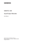
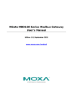
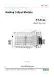
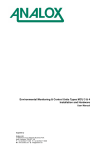
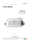
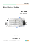
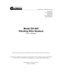
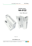
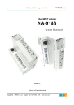
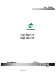
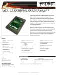
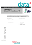
Analog Output
User Manual
Copyright(C) * CREVIS Co.,Ltd * Support +82-31-273-6452 * URL : www.crevis.co.kr
-1-
Analog Output
User Manual
List of revisions
No.
1
Date
Version
2007.12.15 1.00
Revision
created
Copyright(C) * CREVIS Co.,Ltd * Support +82-31-273-6452 * URL : www.crevis.co.kr
-2-
Analog Output
User Manual
Contents
1. Product Specification
1) Environment Specifications
2) General Specifications
2. Current Output Module
1) ST-4112
2) ST-4212
3) ST-4911
3. Voltage Output Module
1) ST-4422
2) ST-4522
3) ST-4622
Copyright(C) * CREVIS Co.,Ltd * Support +82-31-273-6452 * URL : www.crevis.co.kr
-3-
Analog Output
User Manual
1) Environment Specifications
Item
Temperature
Humidity
Specifications
Operating
0℃ to +60℃ (32℉ to 140℉)
Storage
-40℃ to +85℃ (-40℉ to 185℉)
Operating
5 to 90% RH (Non-condensing)
Storage
5 to 90% RH (Non-condensing)
Operating Altitude
2,000m
Mounting
DIN Rail
Remarks
2) General Specifications
Item
Specifications
Wiring I/O Cable
Max. 2.0m , AWG 14
Shock Operating
10G
Shock Non-Operating
30G
Vibration/Sho
ck
Resistance
Remarks
2
Displacement
0.012 Inch p-p from 10~57Hz
Acceleration
2G's from 57~500Hz
Sweep Rate
1 octave per Minute
Axes to test
X, Y, Z
Frequency Sweep per Axis
10
EMC
Confirms to EN-61000-6-2
EMI
Confirms to EN-61000-6-4
Installation Pos. / Protect. Class
Variable / IP20
Certifications
UL, cUL, CE
Copyright(C) * CREVIS Co.,Ltd * Support +82-31-273-6452 * URL : www.crevis.co.kr
-4-
Analog Output
User Manual
Description
- ST-41xx, ST-42xx and ST-49xx series output the standardized 0~20mA, 4~20mA
and 0~1A of current value as a signal.
- It has 2~3 LEDs for status. One is for FnBus, the other are for Field Device status.
- Each output channel is electrically isolated and has distribution capability of 12bit.
- The conversion time of Analog Signal transferred from Field Device is 2ms each for
all channels.
- It is isolated between Field I/O and FnBus by using Photo-coupler.
- It is operated regardless of Field Power supply. When the supplied Field Power has
changed, absolutely the Expansion Field Power Supply (ST-7241) must be used.
1) ST-4112
- 0~20mA 2 channels Current Output Terminal Type, 12bits
◆ Module View
◆ Mapping Data into the image table
Copyright(C) * CREVIS Co.,Ltd * Support +82-31-273-6452 * URL : www.crevis.co.kr
-5-
Analog Output
User Manual
Output Module Data
Output Image Value
No.
Bit7
Bit6
Bit5
Bit4
Bit3
Bit2
Byte0
Analog Output Channel 0 Low Byte
Byte1
Analog Output Channel 0 High Byte
Byte2
Analog Output Channel 1 Low Byte
Byte3
Analog Output Channel 1 High Byte
Bit1
Bit0
Output Module Data
- 2Channels Output Data
Analog Output Channel 0
Analog Output Channel 1
◆ Specification
Output Specification
Outputs per Module
2 Channel Single Ended
Indicators
2 Green/Red Output State, 1 Green/Red FnBus State
Resolution
12Bits : 4.8μA/bit
Output Current Range
0 ~ 20mA
Data Format
16bit Integer(2's compliment)
Module Error
±0.1% Full Scale @ 25˚C
±0.3% Full Scale @ 0˚C, 60˚C
Load Resistance
Max. 500ohm
Conversion Time
2msec/All channel
Calibration
Not Required
Diagnostic
No
Common Type
2 Channel / 1 COM
Module Specification
Power Dissipation
Isolation
Max. 60mA @ 5.0Vdc
I/O to Logic : Photo-coupler Isolation
Field Power : Not Connected
Weight
70g
Size
12mm × 99mm × 70mm
◆ Status LED Description
- Expansion Module Status LED
Copyright(C) * CREVIS Co.,Ltd * Support +82-31-273-6452 * URL : www.crevis.co.kr
-6-
Analog Output
User Manual
State
Not Powered
LED is
To Indicate
Device has no expansion module or may be
not powered
Off
No Initialized
The parameter is not initialized yet
FnBus Connection
Green
FnBus normal operation
FnBus Ready
Flashing Green
FnBus ready
FnBus Fault
Flashing Red
Device Fault
Red
FnBus time out
FnBus failed communication
Device fault
- Channel Status LED
Input Command
LED is
Description
Nominal
Green
Normal operation
Channel Fault
Red
Channel open
◆ Module Wire Diagram
- Wiring Description
Pin No.
Description
Pin No.
Description
Copyright(C) * CREVIS Co.,Ltd * Support +82-31-273-6452 * URL : www.crevis.co.kr
-7-
Analog Output
User Manual
0
Output Channel 0
1
Output Channel 1
2
NC
3
NC
4
Output Channel Common (0V)
5
Output Channel Common (0V)
6
Chassis Ground / Shield
7
Chassis Ground / Shield
2) ST-4212
- 4~20mA 2 channels Current Output Terminal Type, 12bits
◆ Module View
◆ Mapping Data into the image table
Output Module Data
Output Image Value
Copyright(C) * CREVIS Co.,Ltd * Support +82-31-273-6452 * URL : www.crevis.co.kr
-8-
Analog Output
User Manual
No.
Bit7
Bit6
Bit5
Bit4
Bit3
Bit2
Byte0
Analog Output Channel 0 Low Byte
Byte1
Analog Output Channel 0 High Byte
Byte2
Analog Output Channel 1 Low Byte
Byte3
Analog Output Channel 1 High Byte
Bit1
Bit0
Output Module Data
- 2Channels Output Data
Analog Output Channel 0
Analog Output Channel 1
◆ Specification
Output Specification
Outputs per Module
2 Channel Single Ended
Indicators
2 Green/Red Output State, 1 Green/Red FnBus State
Resolution
12Bits : 3.9μA/bit
Output Current Range
4 ~ 20mA
Data Format
16bit Integer(2's compliment)
Module Error
±0.1% Full Scale @ 25˚C
±0.3% Full Scale @ 0˚C, 60˚C
Load Resistance
Max. 500ohm
Conversion Time
2msec/All channel
Calibration
Not Required
Diagnostic
No
Common Type
2 Channel / 1 COM
Module Specification
Power Dissipation
Max. 60mA @ 5.0Vdc
I/O to Logic : Photo-coupler Isolation
Isolation
Field Power : Not Connected
Weight
70g
Size
12mm × 99mm × 70mm
◆ Status LED Description
- Expansion Module Status LED
State
LED is
To Indicate
Copyright(C) * CREVIS Co.,Ltd * Support +82-31-273-6452 * URL : www.crevis.co.kr
-9-
Analog Output
User Manual
Not Powered
Device has no expansion module or may be
not powered
Off
No Initialized
The parameter is not initialized yet
FnBus Connection
Green
FnBus normal operation
FnBus Ready
Flashing Green
FnBus ready
FnBus Fault
Flashing Red
Device Fault
Red
FnBus time out
FnBus failed communication
Device fault
- Channel Status LED
Input Command
LED is
Description
Nominal
Green
Normal operation
Channel Fault
Red
Channel open
◆ Module Wire Diagram
- Wiring Description
Pin No.
Description
Pin No.
Description
0
Output Channel 0
1
Output Channel 1
2
NC
3
NC
Copyright(C) * CREVIS Co.,Ltd * Support +82-31-273-6452 * URL : www.crevis.co.kr
- 10 -
Analog Output
User Manual
4
Output Channel Common
5
Output Channel Common
6
Chassis Ground / Shield
7
Chassis Ground / Shield
3) ST-4911
- 0~1A 1 channels Current Output Terminal Type, 12bits
◆ Module View
◆ Mapping Data into the image table
Output Module Data
Output Image Value
No.
Bit7
Bit6
Bit5
Bit4
Bit3
Bit2
Bit1
Copyright(C) * CREVIS Co.,Ltd * Support +82-31-273-6452 * URL : www.crevis.co.kr
Bit0
- 11 -
Analog Output
User Manual
Byte0
Analog Output Channel 0 Low Byte
Byte1
Analog Output Channel 0 High Byte
Output Module Data
- 1Channel Output Data
Analog Output Channel 0
◆ Specification
Output Specification
Outputs per Module
1 Channel Single Ended
Indicators
1 Green/Red Output State, 1 Green/Red FnBus State
Resolution
12Bits : 0.244mA/bit
Output Current Range
0 to 1A
Data Format
16bit Integer (2's compliment)
Module Error
1% Full Scale @ 25˚C
3% Full Scale @ -20˚C, 60˚C
Load Resistence
13ohm, ±5%
Conversion Time
1msec/All channel
Calibration
Not Required
Diagnostic
No
Common Type
1 Channel / 1 COM
Module Specification
Power Dissipation
Max. 60mA @ 5.0Vdc
I/O to Logic : Photo-coupler Isolation
Isolation
Field Power : Not Connected
Weight
70g
Size
12mm × 99mm × 70mm
◆ Status LED Description
- Expansion Module Status LED
State
LED is
To Indicate
Copyright(C) * CREVIS Co.,Ltd * Support +82-31-273-6452 * URL : www.crevis.co.kr
- 12 -
Analog Output
User Manual
Not Powered
Device has no expansion module or may be
not powered
Off
No Initialized
The parameter is not initialized yet
FnBus Connection
Green
FnBus normal operation
FnBus Ready
Flashing Green
FnBus ready
FnBus Fault
Flashing Red
Device Fault
Red
FnBus time out
FnBus failed communication
Device fault
- Channel Status LED
Input Command
LED is
Description
Nominal
Green
Normal operation
Channel Fault
Red
Channel open
◆ Module Wire Diagram
- Wiring Description
Signal for Left Terminal
Pin No.
Description
Pin No.
Description
Copyright(C) * CREVIS Co.,Ltd * Support +82-31-273-6452 * URL : www.crevis.co.kr
- 13 -
Analog Output
User Manual
0
NC
1
NC
2
FG
3
FG
4
Field Power (0V)
5
Field Power (0V)
6
Field Power (+24Vdc)
7
Field Power (+24Vdc)
Signal for Right Terminal
Pin No.
Description
Pin No.
Description
0
Output Channel 0
1
Output Channel 0
2
NC
3
NC
4
Field Power (0V), Common
5
Field Power (0V), Common
6
Field Power (7~15Vdc)
7
Field power (7~15Vdc)
Copyright(C) * CREVIS Co.,Ltd * Support +82-31-273-6452 * URL : www.crevis.co.kr
- 14 -
Analog Output
User Manual
Description
- ST-44xx ,ST-45xx and ST-46xx series output the standardized 0~10V, -10~10V and
0~5V of voltage value as a signal.
- It has 3 LEDs for status. One is for FnBus, the other are for Field Device status.
- Each input channel is electrically isolated and has distribution capability of 12bit.
- The conversion time of Analog Signal transferred from Field Device is 2ms each for all
channel.
- It is isolated between Field I/O and FnBus by using Photo-coupler.
- It is operated regardless of Field Power supply. When the supplied Field Power has
changed, absolutely the Expansion Field Power Supply (ST-7241) must be used.
1) ST-4422
- 0~10V 2 channels Voltage Output Terminal Type, 12bits
Copyright(C) * CREVIS Co.,Ltd * Support +82-31-273-6452 * URL : www.crevis.co.kr
- 15 -
Analog Output
User Manual
◆ Module View
◆ Mapping Data into the image table
Output Module Data
Output Image Value
No.
Bit7
Bit6
Bit5
Bit4
Bit3
Bit2
Byte0
Analog Output Channel 0 Low Byte
Byte1
Analog Output Channel 0 High Byte
Byte2
Analog Output Channel 1 Low Byte
Byte3
Analog Output Channel 1 High Byte
Bit1
Bit0
Output Module Data
- 2Channels Output Data
Analog Output Channel 0
Analog Output Channel 1
◆ Specification
Output Specification
Copyright(C) * CREVIS Co.,Ltd * Support +82-31-273-6452 * URL : www.crevis.co.kr
- 16 -
Analog Output
User Manual
Outputs per Module
2 Channel Single Ended
Indicators
2 Green/Red Output State, 1 Green/Red FnBus State
Resolution
12Bits : 2.4mV/bit
Output Voltage Range
0Vdc to 10Vdc
Data Format
16bit Integer(2's compliment)
±0.1% Full Scale @ 25˚C
Module Error
±0.3% Full Scale @ 0˚C, 60˚C
Load Resistance
Max. 5Kohm
Conversion Time
2msec/All channel
Calibration
Not Required
Diagnostic
No
Common Type
2 Channel / 1COM
Module Specification
Power Dissipation
Max. 155mA @ 5.0Vdc
I/O to Logic : Photo-coupler Isolation
Isolation
Field Power : Not Connected
Weight
70g
Size
12mm × 99mm × 70mm
◆ Status LED Description
- Expansion Module Status LED
State
Not Powered
LED is
To Indicate
Device has no expansion module or may be
not powered
Off
No Initialized
The parameter is not initialized yet
FnBus Connection
Green
FnBus normal operation
FnBus Ready
Flashing Green
FnBus ready
FnBus Fault
Flashing Red
Device Fault
Red
FnBus time out
FnBus failed communication
Device fault
- Channel Status LED
Input Command
LED is
Description
Nominal
Green
Normal operation
Channel Fault
Red
Channel open
◆ Module Wire Diagram
Copyright(C) * CREVIS Co.,Ltd * Support +82-31-273-6452 * URL : www.crevis.co.kr
- 17 -
Analog Output
User Manual
- Wiring Description
Pin No.
Description
Pin No.
Description
0
Output Channel 0
1
Output Channel 1
2
NC
3
NC
4
Output Channel Common(0V)
5
Output Channel Common(0V)
6
Chassis Ground / Shield
7
Chassis Ground / Shield
2) ST-4522
Copyright(C) * CREVIS Co.,Ltd * Support +82-31-273-6452 * URL : www.crevis.co.kr
- 18 -
Analog Output
User Manual
-10~10V 2 channels Voltage Output Terminal Type, 12bits
◆ Module View
◆ Mapping Data into the image table
Output Module Data
Output Image Value
No.
Bit7
Bit6
Bit5
Bit4
Bit3
Bit2
Byte0
Analog Output Channel 0 Low Byte
Byte1
Analog Output Channel 0 High Byte
Byte2
Analog Output Channel 1 Low Byte
Byte3
Analog Output Channel 1 High Byte
Bit1
Bit0
Output Module Data
- 2Channels Output Data
Analog Output Channel 0
Analog Output Channel 1
◆ Specification
Copyright(C) * CREVIS Co.,Ltd * Support +82-31-273-6452 * URL : www.crevis.co.kr
- 19 -
Analog Output
User Manual
Output Specification
Outputs per Module
2 Channel Single Ended
Indicators
2 Green/Red Output State, 1 Green/Red FnBus State
Resolution
12Bits : 4.8mV/bit
Output Voltage Range
-10Vdc to 10Vdc
Data Format
16bit Integer(2's compliment)
±0.1% Full Scale @ 25˚C
Module Error
±0.3% Full Scale @ 0˚C, 60˚C
Load Resistance
Max. 5Kohm
Conversion Time
2msec/All channel
Calibration
Not Required
Diagnostic
No
Common Type
2 Channel / 1 COM
Module Specification
Power Dissipation
Max. 155mA @ 5.0Vdc
I/O to Logic : Photo-coupler Isolation
Isolation
Field Power : Not Connected
Weight
70g
Size
12mm × 99mm × 70mm
◆ Status LED Description
- Expansion Module Status LED
State
Not Powered
LED is
To Indicate
Device has no expansion module or may be
not powered
Off
No Initialized
The parameter is not initialized yet
FnBus Connection
Green
FnBus normal operation
FnBus Ready
Flashing Green
FnBus ready
FnBus Fault
Flashing Red
Device Fault
Red
FnBus time out
FnBus failed communication
Device fault
- Channel Status LED
Input Command
LED is
Description
Nominal
Green
Normal operation
Channel Fault
Red
Channel open
◆ Module Wire Diagram
Copyright(C) * CREVIS Co.,Ltd * Support +82-31-273-6452 * URL : www.crevis.co.kr
- 20 -
Analog Output
User Manual
- Wiring Description
Pin No.
Description
Pin No.
Description
0
Output Channel 0
1
Output Channel 1
2
NC
3
NC
4
Output Channel Common(0V)
5
Output Channel Common(0V)
6
Chassis Ground / Shield
7
Chassis Ground / Shield
3) ST-4622
Copyright(C) * CREVIS Co.,Ltd * Support +82-31-273-6452 * URL : www.crevis.co.kr
- 21 -
Analog Output
User Manual
- 0~5V 2 channels Voltage Output Terminal Type, 12bits
◆ Module View
◆ Mapping Data into the image table
Output Module Data
Output Image Value
No.
Bit7
Bit6
Bit5
Bit4
Bit3
Bit2
Byte0
Analog Output Channel 0 Low Byte
Byte1
Analog Output Channel 0 High Byte
Byte2
Analog Output Channel 1 Low Byte
Byte3
Analog Output Channel 1 High Byte
Bit1
Bit0
Output Module Data
- 2Channels Output Data
Analog Output Channel 0
Analog Output Channel 1
◆ Specification
Copyright(C) * CREVIS Co.,Ltd * Support +82-31-273-6452 * URL : www.crevis.co.kr
- 22 -
Analog Output
User Manual
Output Specification
Outputs per Module
2 Channel Single Ended
Indicators
2 Green/Red Output State, 1 Green/Red FnBus State
Resolution
12Bits : 1.2mV/bit
Output Voltage Range
0Vdc to 5Vdc
Data Format
16bit Integer (2's compliment)
±0.1% Full Scale @ 25˚C
Module Error
±0.3% Full Scale @ 0˚C, 60˚C
Load Resistance
Max. 5Kohm
Conversion Time
2msec/All channel
Calibration
Not Required
Diagnostic
No
Common Type
2 Channel / 1 COM
Module Specification
Power Dissipation
Max. 155mA @ 5.0Vdc
I/O to Logic : Photo-coupler Isolation
Isolation
Field Power : Not Connected
Weight
70g
Size
12mm × 99mm × 70mm
◆ Status LED Description
- Expansion Module Status LED
State
Not Powered
LED is
To Indicate
Device has no expansion module or may be
not powered
Off
No Initialized
The parameter is not initialized yet
FnBus Connection
Green
FnBus normal operation
FnBus Ready
Flashing Green
FnBus ready
FnBus Fault
Flashing Red
Device Fault
Red
FnBus time out
FnBus failed communication
Device fault
- Channel Status LED
Input Command
LED is
Description
Nominal
Green
Normal operation
Channel Fault
Red
Channel open
◆ Module Wire Diagram
Copyright(C) * CREVIS Co.,Ltd * Support +82-31-273-6452 * URL : www.crevis.co.kr
- 23 -
Analog Output
User Manual
- Wiring Description
Pin No.
Description
Pin No.
Description
0
Output Channel 0
1
Output Channel 1
2
NC
3
NC
4
Output Channel Common(0V)
5
Output Channel Common(0V)
6
Chassis Ground / Shield
7
Chassis Ground / Shield
Copyright(C) * CREVIS Co.,Ltd * Support +82-31-273-6452 * URL : www.crevis.co.kr
- 24 -
Analog Output
User Manual
Copyright(C) * CREVIS Co.,Ltd * Support +82-31-273-6452 * URL : www.crevis.co.kr
- 25 -