1
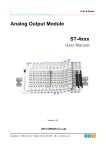
1 FnIO PROFIBUS Adapter NA-9122 FnIO S-Series PROFIBUS Adapter NA-9122 User Manual Version 1.05 2013 CREVIS Co.,Ltd Copyright(C) CREVIS Co.,Ltd Support +82-31-899-4599 URL : www.crevis.co.kr 2 FnIO PROFIBUS Adapter NA-9122 FnIO S-Series DOCUMENT CHANGE SUMMARY REV PAGE 1.0 New Document 1.01 11 DATE EDITOR 2011/10/07 JE Kang IO LED Status Flashing Red ↔ Red 2011/10/21 JE Kang Parameter assign Delete 2011/11/11 JE Kang Add your experience 2012/1/13 JE KANG 2012/2/13 JE KANG Add the Certificate RoHS 2012/3/22 JE KANG 1.04 Changed Crevis TEL 2013/4/4 JE KANG 1.05 Environment Spec. 50℃→55℃ (UL Temp) 2013/7/3 JE Kang 1.02 1.03 1.03 5 20-29 10, 31 REMARKS Changed DPV1 service Changed Status LED, Trouble Shooting Changed Cover Copyright(C) CREVIS Co.,Ltd Support +82-31-899-4599 URL : www.crevis.co.kr 3 FnIO PROFIBUS Adapter NA-9122 FnIO S-Series CONTENTS 1. Important Notes ......................................................................................................................................................... 5 1.1. 2. 1.1.1. Symbols ......................................................................................................................................................... 6 1.1.2. Safety Notes ................................................................................................................................................ 6 1.1.3. Certification ................................................................................................................................................. 6 Specification ................................................................................................................................................................. 7 2.1. 2.1.1. 2.2. 5. NA-9122 ........................................................................................................................................................ 7 Specification ................................................................................................................................................ 8 General Specification............................................................................................................................... 8 2.2.2. Interface Specification............................................................................................................................. 9 LED Indicator............................................................................................................................................. 10 2.3.1. Module Status LED (MOD) ................................................................................................................. 10 2.3.2. Network Status LED (NET) .................................................................................................................. 10 2.3.3. Expansion Module Status LED (I/O) ............................................................................................... 11 2.3.4. Field Power Status LED ........................................................................................................................ 11 Dimension.................................................................................................................................................................... 12 3.1. 4. The Interface ............................................................................................................................................... 7 2.2.1. 2.3. 3. Safety Instruction ...................................................................................................................................... 6 NA-9122 ...................................................................................................................................................... 12 Mechanical Set Up................................................................................................................................................... 13 4.1. Total Expansion........................................................................................................................................ 13 4.2. Plugging and Removal of the Components. .............................................................................. 13 4.3. Internal FnBus/Field Power Contacts ............................................................................................. 14 PROFIBUS Electrical Interface ............................................................................................................................. 15 5.1. FnBus System ............................................................................................................................................ 15 5.2. PROFIBUS Electrical Interface ............................................................................................................ 17 5.2.1. NA-9122 ...................................................................................................................................................... 17 5.2.2. Terminator Resistor ................................................................................................................................ 18 Copyright(C) CREVIS Co.,Ltd Support +82-31-899-4599 URL : www.crevis.co.kr 4 FnIO PROFIBUS Adapter NA-9122 5.2.3. PROFIBUS Address Setup .................................................................................................................... 19 5.2.4. Choice of PROFIBUS data transfer cable type ........................................................................... 20 5.2.5. I/O Process Image Map ....................................................................................................................... 21 5.3. 6. 7. FnIO S-Series Example ....................................................................................................................................................... 22 5.3.1. Example of Output Process Image(Output Register) Map .................................................. 22 5.3.2. GSD & I/O Module Setting ................................................................................................................ 23 NA-9122 DPV1 Service Specification .............................................................................................................. 24 6.1. Supported service ................................................................................................................................... 24 6.2. MSAC1 Read (PROFIBUS-DP Extensions to EN50170) ........................................................... 24 6.3. MSAC1 Write (PROFIBUS-DP Extensions to EN50170) .......................................................... 26 6.4. Error_Decode(PROFIBUS-DP Extensions to EN50170) ............................................................ 27 6.5. Error Code_1(PROFIBUS-DP Extensions to EN50170) ............................................................. 27 6.6. Diagnostics................................................................................................................................................. 28 Trouble Shooting...................................................................................................................................................... 31 7.1. How to diagnose by LED indicator................................................................................................. 31 APPENDIX A ......................................................................................................................................................................... 33 A.1. Product List............................................................................................................................................................. 33 A.2. Glossary .................................................................................................................................................................... 35 Copyright(C) CREVIS Co.,Ltd Support +82-31-899-4599 URL : www.crevis.co.kr 5 FnIO PROFIBUS Adapter NA-9122 FnIO S-Series 1. Important Notes Solid state equipment has operational characteristics differing from those of electromechanical equipment. Safety Guidelines for the Application, Installation and Maintenance of Solid State Controls describes some important differences between solid state equipment and hard-wired electromechanical devices. Because of this difference, and also because of the wide variety of uses for solid state equipment, all persons responsible for applying this equipment must satisfy themselves that each intended application of this equipment is acceptable. In no event will CREVIS be responsible or liable for indirect or consequential damages resulting from the use or application of this equipment. The examples and diagrams in this manual are included solely for illustrative purposes. Because of the many variables and requirements associated with any particular installation, CREVIS cannot assume responsibility or liability for actual use based on the examples and diagrams. Warning! If you don’t follow the directions, it could cause a personal injury, damage to the equipment or explosion Do not assemble the products and wire with power applied to the system. Else it may cause an electric arc, which can result into unexpected and potentially dangerous action by field devices. Arching is explosion risk in hazardous locations. Be sure that the area is non-hazardous or remove system power appropriately before assembling or wiring the modules. Do not touch any terminal blocks or IO modules when system is running. Else it may cause the unit to an electric shock or malfunction. Keep away from the strange metallic materials not related to the unit and wiring works should be controlled by the electric expert engineer. Else it may cause the unit to a fire, electric shock or malfunction. Caution! If you disobey the instructions, there may be possibility of personal injury, damage to equipment or explosion. Please follow below Instructions. • Check the rated voltage and terminal array before wiring. Avoid the circumstances over 55℃ of temperature. Avoid placing it directly in the sunlight. • Avoid the place under circumstances over 85% of humidity. • Do not place Modules near by the inflammable material. Else it may cause a fire. • Do not permit any vibration approaching it directly. • Go through module specification carefully, ensure inputs, output connections are made with the specifications. Use standard cables for wiring. • Use Product under pollution degree 2 environment. Copyright(C) CREVIS Co.,Ltd Support +82-31-899-4599 URL : www.crevis.co.kr 6 FnIO PROFIBUS Adapter NA-9122 1.1. FnIO S-Series Safety Instruction 1.1.1. Symbols Identifies information about practices or circumstances that can cause an explosion in a hazardous environment, which may lead to personal injury or death property damage or economic loss. Identifies information that is critical for successful application and understanding of the product. Identifies information about practices or circumstances that can lead to personal injury, property damage, or economic loss. Attentions help you to identity a hazard, avoid a hazard, and recognize the consequences. 1.1.2. Safety Notes The modules are equipped with electronic components that may be destroyed by electrostatic discharge. When handling the modules, ensure that the environment (persons, workplace and packing) is well grounded. Avoid touching conductive components, e.g. FnBUS Pin. 1.1.3. Certification c-UL-us UL Listed Industrial Control Equipment, certified for U.S. and Canada See UL File E235505 DNV CERTIFICATE No. A-10666 CE Certificate EN 61000-6-2; Industrial Immunity EN 61000-6-4; Industrial Emissions FCC / LR RoHS (EU, CHINA) Copyright(C) CREVIS Co.,Ltd Support +82-31-899-4599 URL : www.crevis.co.kr 7 FnIO PROFIBUS Adapter NA-9122 2. Specification 2.1. The Interface 2.1.1. NA-9122 Copyright(C) CREVIS Co.,Ltd Support +82-31-899-4599 URL : www.crevis.co.kr FnIO S-Series 8 FnIO PROFIBUS Adapter NA-9122 2.2. Specification 2.2.1. General Specification General Specification Supply voltage : 24Vdc nominal Supply voltage range : 11~28.8Vdc Protection : Output current limit (Min. 1.5A) Reverse polarity protection 60mA typical @24Vdc 1.5A @5Vdc System power to internal logic : Non-isolation System power to I/O driver : Isolation Supply voltage : 24Vdc nominal Supply voltage range : 11~28.8Vdc System Power Power Dissipation Current for I/O Module Isolation Field Power Max. Current Field Power Contact Weight Module Size Environment Condition DC 10A Max. 155g 45mm x 99mm x 70mm Refer to Environment Specification Environmental Specifications Operating Temperature -20 to 55℃ Non-Operating Temperature -40℃ to 85℃ 5%~90% non-condensing 2000m DIN rail Relative Humidity Operating Altitude Mounting Copyright(C) CREVIS Co.,Ltd Support +82-31-899-4599 URL : www.crevis.co.kr FnIO S-Series 9 FnIO PROFIBUS Adapter NA-9122 FnIO S-Series 2.2.2. Interface Specification Interface Specification, NA-9122 Redundancy Repeater Control Signal Freeze mode Sync mode Auto baudrate Fail safe mode Station type FMS support Number of Station Not supported TTL Support Support Support Support Slave Not supported 100 Station/Max (Rotary switch #0~99) Number of Expansion I/O slots I/O Data Size Baud Rate Max. 32 slots Total: Input 128bytes / Output 128bytes - Max. Discrete I/O: Input 1024points/Output 1024points - Max. Analog I/O: Input 64channels/Output 64channels 1 green/red Module Status Indicator 1 green Network Status Indicator 1 green/red Expansion Module Status indicator 1 green Field Power Status indicator 9.6K~12M(1.2Km~100m) Communication Speed 9.6K~12Mbps (Auto baudrate selection) Module Location Starter module - left side of FnIO system Field Power detection Detect Field Power @11Vdc Indicators Copyright(C) CREVIS Co.,Ltd Support +82-31-899-4599 URL : www.crevis.co.kr 10 FnIO PROFIBUS Adapter NA-9122 2.3. FnIO S-Series LED Indicator 2.3.1. Module Status LED (MOD) State LED is : To indicate : No Power Off No power is supplied to the unit. Device Operational Device in Standby Green Flashing Green The unit is operating in normal condition. The device needs commissioning due to configuration missing, incomplete or incorrect. Minor Fault Flashing Red Recoverable Fault Unrecoverable Fault Red Rotary switch configuration error 2.3.2. Network Status LED (NET) State LED is : To indicate : Not Powered Not On-line On-line, Not connected On-line, Connected Off Device is not on-line or may not be powered Flashing Green Device is on-line but has no connections in the established state. - Not allocated to a master Device is on-line and allocated to a master Green Copyright(C) CREVIS Co.,Ltd Support +82-31-899-4599 URL : www.crevis.co.kr 11 FnIO PROFIBUS Adapter NA-9122 FnIO S-Series 2.3.3. Expansion Module Status LED (I/O) State Not Powered No Expansion Module FnBus On-line, Do not Exchanging I/O FnBus Connection, Run Exchanging IO LED is : To indicate : Off Device has no expansion module or may not be powered Flashing Green FnBus is on-line but does not exchanging I/O data - Passed the expansion module configuration. Green Expansion Slot is connected and run exchanging I/O data FnBus connection fault during exchanging IO Red Expansion Configuration Failed Flashing Red One or more expansion module occurred in fault state. - Changed expansion module configuration. - FnBus communication failure. Failed to initialize expansion module - Detected invalid expansion module ID. - Overflowed Input / Output Size - Too many expansion module - Initial protocol failure - Mismatch vendor code between adapter and expansion module. 2.3.4. Field Power Status LED State Not Supplied Field Power Supplied Field Power LED is : To indicate : Off Not supplied 24V dc field power Green Supplied 24V dc field power Copyright(C) CREVIS Co.,Ltd Support +82-31-899-4599 URL : www.crevis.co.kr 12 FnIO PROFIBUS Adapter NA-9122 FnIO S-Series 3. Dimension 3.1. NA-9122 (mm) Copyright(C) CREVIS Co.,Ltd Support +82-31-899-4599 URL : www.crevis.co.kr 13 FnIO PROFIBUS Adapter NA-9122 FnIO S-Series 4. Mechanical Set Up 4.1. Total Expansion The number of the module assembly that can be connected is 32. So the maximum length is 426mm Exception. ST-2748 is excepted to calculate maximum length because that is double width module. 4.2. Plugging and Removal of the Components. Before work is done on the components, the voltage supply must be turned off. As above figure in order to safeguard the FnIO module from jamming, it should be fixed onto the DIN rail with locking level. To do so, fold on the upper of the locking lever. To pull out the FnIO module, unfold the locking lever as below figure. Copyright(C) CREVIS Co.,Ltd Support +82-31-899-4599 URL : www.crevis.co.kr 14 FnIO PROFIBUS Adapter NA-9122 4.3. FnIO S-Series Internal FnBus/Field Power Contacts Communication between the NA series and the expansion module as well as system / field power supply of the bus modules is carried out via the internal bus. It is comprised of 6 data pin and 2 field power pin. Do not touch data and field power pins in order to avoid soiling and damage by noise. Copyright(C) CREVIS Co.,Ltd Support +82-31-899-4599 URL : www.crevis.co.kr 15 FnIO PROFIBUS Adapter NA-9122 FnIO S-Series 5. PROFIBUS Electrical Interface 5.1. FnBus System • Network Adapter Module The Network Adapter Module forms the link between the field bus and the field devices with the Expansion Modules. The connection to different field bus systems can be established by each of the corresponding Network Adapter Module, e.g. for SyncNet, PROFIBUS, CANopen, DeviceNet, Ethernet/IP, CC-Link, MODBUS/Serial, MODBUS/TCP etc. Copyright(C) CREVIS Co.,Ltd Support +82-31-899-4599 URL : www.crevis.co.kr 16 FnIO PROFIBUS Adapter NA-9122 • Expansion Module The Expansion Modules are supported a variety of input and output field devices. There are digital and analog input/output modules and special function modules. • Two types of FnBus Message - Service Messaging - I/O Messaging FnBus Pin Description No. Name Description 1 2 3 4 5 6 7 8 Vcc GND Token Output Serial Output Serial Input Reserved Field GND Field Vcc System supply voltage (5V dc). System Ground. Token output port of Processor module. Transmitter output port of Processor module. Receiver input port of Processor module. Reserved for bypass Token. Field Ground. Field supply voltage (24Vdc). Copyright(C) CREVIS Co.,Ltd Support +82-31-899-4599 URL : www.crevis.co.kr FnIO S-Series 17 FnIO PROFIBUS Adapter NA-9122 5.2. FnIO S-Series PROFIBUS Electrical Interface 5.2.1. NA-9122 Dsub 9 (Female) 1 2 3 Signal Name RXD/TXD-P 4 CNTR-P 5 6 7 8 9 DGND VP RXD/TXD-N - Description Receive/Transmit data-plus(B wire) Repeater control signal(direction control), RTS signal Data ground(reference potential for VP) Supply voltage-Plus(P5V) Receive/Transmit data-minus(A-wire) All Fieldbus devices which use a standard 9-pin Sub-D connector should provide the VP and DGND signals on the bus connector in addition to the receive and transmit signals. With all other connector types, only the receive and transmit signals need to be connected. Make sure that the connector type used is suitable for the selected baud rate. If optional signal are provided, they must also comply with EN50170 Volume 2 and they must be correctly described in the respective GSD file. To prevent EMC interface from entering the device, the cable shield should be connected to the functional ground of the device (generally the electrically conductive case). This is done by connecting the cable shield to the metal case of the Sub-D connector and the functional ground over a larger area. The bus connector must have a low-impedance connection to the cable shield. The data transfer technology of the serial bus system, which uses a shielded twisted pair data cable, is described in the specification of the interface-immune RS 485 interface standard. To allow correct bus termination, each station must connect the signals DGND and VP (5V) to pins 5 and 6 of the connector, respectively. The 5V supply for the terminating resistors (VP) should have a minimum current rating of 10mA (the current load can increase to 12mA if a NULL signal is sent through the bus). The current rating should be increased to app. 90mA if you need to be able to supply other types of devices on the bus such as bus terminals and optical fiber cable drivers. Due to the capacitive load of the station and the resulting cable reflections, bus connectors should be provided with built-in series inductors as shown below. The use of an incorrect supply voltage or frequency can cause severe damage to the component. Copyright(C) CREVIS Co.,Ltd Support +82-31-899-4599 URL : www.crevis.co.kr 18 FnIO PROFIBUS Adapter NA-9122 FnIO S-Series 5.2.2. Terminator Resistor In order to minimize cable reflections and ensure a defined noise level on the data lines, the data transfer cable must be terminated at both ends with a terminating resister combination as follows. Copyright(C) CREVIS Co.,Ltd Support +82-31-899-4599 URL : www.crevis.co.kr 19 FnIO PROFIBUS Adapter NA-9122 FnIO S-Series 5.2.3. PROFIBUS Address Setup Each PROFIBUS Adapter could have a unique address (from 1 to 99) so that it can be addressed independently from other nodes. The address 0 is reserved to identify a broadcast exchange. No response is returned to broadcast requests sent by the master. X 10 (MSD) X 1 (LSD) The above figure shows MAC ID 27(=2*10 + 7*1) of a slave node. ◆ Communication Speed Setting - See Master Module Setting about communication speed setting. MAC ID addresses have to be unique throughout the entire interconnected networks. Copyright(C) CREVIS Co.,Ltd Support +82-31-899-4599 URL : www.crevis.co.kr 20 FnIO S-Series FnIO PROFIBUS Adapter NA-9122 5.2.4. Choice of PROFIBUS data transfer cable type Depending on the application, the user can choose between electrical and optical fiber data transfer cables. The following types of electrical data cables can be used: - Standard bus cable - Standard bus cable with halogen-free sheath (type FRNC) - Cable with PE Sheath for use in the food and manufacturing industries. (It differs from the standard bus cable solely in the cable sheath). - Direct buried cable with additional protective sheath for laying in the ground. - Trailing cable ( this is a special cable type which is used where parts of the machine move occasionally or continuously). - Festooned cable. Compared to a trailing cable, a festooned cable has an additional strain relief element. The bus cable is specified in EN 50170 part 8-2 as " Cable Type A", and should comply with the parameters in the following table. Cable Type B, which is also described in EN 50170, is outdated and should no longer be used. Table 1. show the parameters for standard type A bus cables. Parameter Cable type A Characteristic impedance in Ω 135..165 at a frequency of (3..20MHz) Operating capacity(pF/m) < 30 <=110 Loop resistance (Ω/㎞) >0.64* Core diameter (mm) >0.34* Cora cross-section (mm) * The cable cross-sections used should be compatible with the mechanical specifications of the bus interface connector The cable parameters specified for standard Type A bus cables result in the maximum length of each bus segment for the respective data transfer rate shown in Table 2. Table 2 : Maximum cable lengths per segment Baudrate 9.6 19.2 45.45 93.75 Max. segment 1200 1200 1200 1200 Length in ‘m’(m) 187.5 500 1500 3000 6000 12000 1000 400 200 100 100 100 Important : In a PROFIBUS-DP/FMS installation, you must choose a data transfer rate which is supported by all devices connected to the bus. The chosen data transfer rate then determines the maximum segment lengths as shown above. The maximum admissible distance between two bus stations in each PROFIBUS network can be calculated as follows: (NO_REP+1)*Segment length NO_REP=The maximum number of repeaters connected in series(depends on repeater type). Example : The repeater manufacture specifications allow nine repeaters to be connected in series. The maximum distance between two bus stations at a data transfer rate of 1500 Kbit/s is then as follow: (9+1)*200m=2000m Copyright(C) CREVIS Co.,Ltd Support +82-31-899-4599 URL : www.crevis.co.kr 21 FnIO PROFIBUS Adapter NA-9122 FnIO S-Series 5.2.5. I/O Process Image Map An expansion module may have 3 types of data as I/O data, configuration parameter and memory register. The data exchange between network adapter and expansion modules is done via an I/O process image data by FnBus protocol. The following figure shows the data flow of process image between network adapter and expansion modules. Copyright(C) CREVIS Co.,Ltd Support +82-31-899-4599 URL : www.crevis.co.kr 22 FnIO S-Series FnIO PROFIBUS Adapter NA-9122 5.3. Example 5.3.1. Example of Output Process Image(Output Register) Map For example slot configuration Slot Address #0 #1 #2 #3 #4 #5 #6 #7 #8 #9 #10 #11 Module Description PROFIBUS Adapter 4-discrete output 8-discrete output 2-analog output 16-discrete output 4-discrete output 8-discrete output 2-relay output 2-relay output 2-analog output 16-discrete output 4-discrete output Output Process Image Mode#0 (Uncompressed Output Processing Data) Byte Write Byte 0 Write Byte 1 Write Byte 2 Write Byte 3 Write Byte 4 Write Byte 5 Write Byte 6 Write Byte 7 Write Byte 8 Write Byte 9 Write Byte 10 Write Byte 11 Write Byte 12 Write Byte 13 Write Byte 14 Write Byte 15 Write Byte 16 Write Byte 17 Write Byte 18 Slot # Slot 1 Slot 2 Slot 3 Slot 4 Slot 5 Slot 6 Slot 7 Slot 8 Slot 9 Slot 10 Slot 11 Copyright(C) CREVIS Co.,Ltd Bit 7 Bit 6 Bit 5 Not used Bit 2 Bit 1 Bit 0 Discrete Output 4 points Discrete Output 8 points Analog Output Ch0 low byte Analog Output Ch0 high byte Analog Output Ch1 low byte Analog Output Ch1 high byte Discrete Output low 8 points Discrete Output high 8 points Not used Discrete Output 4 points Discrete Output 8 points Discrete Out 2 pts Not used Discrete Out 2 pts Not used Analog Output Ch0 low byte Analog Output Ch0 high byte Analog Output Ch1 low byte Analog Output Ch1 high byte Discrete Output low 8 points Discrete Output high 8 points Reserved Discrete Output 4 points Support +82-31-899-4599 Bit 4 Bit 3 URL : www.crevis.co.kr 23 FnIO PROFIBUS Adapter NA-9122 FnIO S-Series 5.3.2. GSD & I/O Module Setting GSD (Electronic data sheet of a device) files contain and describe the functions and characteristics of PROFIBUS devices. The abbreviation GSD means Generic Station Description (Device Base Files). All the available GSD files together form the device database. When the program is started, the System Configurator automatically retrieves all the GSD files stored in the GSD directory. The device names are placed into an internal into a list. During the configuration, the device-specific data is retrieved directly from the GSD files. If a DP Slave device does not appear in the selection list, a corresponding GSD file can be copied into the GSD directory File > Copy GSD. Another possibility is to copy the GSD file into GSD directory with the Windows Explore and then retrieve the GSD files into the GSD directory with Setting > Path and OK. The GSD files can be viewed with the Tools > GSD Viewer menu. - Hilscher Devices: The GSD files for Hilscher devices are already included and installed. - Other Devices: The respective device manufacturer provides the GSD files for other devices. The GSD files of many vendors are available on the PROFIBUS user organization home page. The GSD directory is adjustable. In order to alter the directory from a previous setting in another directory, use the Setting > Path menu. All GSD files must be placed in this directory. No GSD files are used for PROFIBUS-FMS. Hilscher PROFIBUS-FMS devices as well as Other FMS Devices for all vendors are available in the selection list of the Master. The GSD Files for PROFIBUS-FMS specified by the PNO (PROFIBUS User Organization) are not supported by the System Configurator. Copyright(C) CREVIS Co.,Ltd Support +82-31-899-4599 URL : www.crevis.co.kr 24 FnIO S-Series FnIO PROFIBUS Adapter NA-9122 6. NA-9122 DPV1 Service Specification 6.1. Supported service MSAC1 Read MSAC1 Write MSAC2 Initiate / MSAC2 Abort MSAC2 Read MSAC2 Write 6.2. MSAC1 Read (PROFIBUS-DP Extensions to EN50170) MSAC1 Read Request Parameter Description Remote Address Slave Address (0~99) Slot Number (0~32), 0 : NA-9122 1~32 : IO 1 : Parameter 2 : Memory 253 : FW revision (Data size : 4 bytes) 254 : Vendor Code (Data size : 1 byte) 1~128 Slot Number Index Length NA-9122 Parameter (Hilscher Master Card from Command Message) Byte address Description [0] NA Status 1 [3] Word data format DP Clear action [4] Reaction to FnBus fault Restart on FnBus fault Copyright(C) CREVIS Co.,Ltd Value DPV1 activation Intel Motorola FnBus Stop(IO’s fault action) FnBus Run(Clear output) FnBus run(Hold output) Profibus communication stops Clear input data Stay with the last input value Power reset Auto reset Support +82-31-899-4599 0x80(DPV1 activated) 0x00 0x01 0x00 0x04 0x08 0x00 0x01 0x02 0x00 0x10 URL : www.crevis.co.kr 25 FnIO PROFIBUS Adapter NA-9122 FnIO S-Series Command message for Function Read (Hilscher Master Card from Command Message) Command Message Variable Type Message Header RX Byte TX Byte LN Auto NR Byte A Byte F Byte B Byte E Byte Extended Message Header Device Adr. Byte Data Area Byte Data Adr. Word Data Idx. Byte Data count Byte Data type Byte Function Byte Copyright(C) CREVIS Co.,Ltd Value 3 16 Signification 0 0 0 0x11 0 Receiver Transmitter Length of message Number of the message No answer Error, state Command = MSAC1_Read_Write Extension 0 ~ 99 0 0 ~ 254 1, 2, 253, 254 0 ~ 128 0 or 10 1 Remote address(slave station) Data area, unused Slot number Index Length of data block to be read Data type, byte string Function MSAC1_Read Support +82-31-899-4599 URL : www.crevis.co.kr 26 FnIO PROFIBUS Adapter NA-9122 6.3. FnIO S-Series MSAC1 Write (PROFIBUS-DP Extensions to EN50170) MSAC1 Write Request Parameter Remote Address Slot Number Index Length Data Description Slave Address (0~99) Slot Number(0~32), 0 : NA9122 1~32 : IO 1 : Parameter 2 : Memory 1~128 1. Parameter 2. Memory *Refer to “FnIO configuration parameter” document. Command message for Function Write (Hilscher Master Card from Command Message) Command Message Variable Type Message Header RX Byte TX Byte LN Auto NR Byte A Byte F Byte B Byte E Byte Extended Message Header Device Adr. Byte Data Area Byte Data Adr. Word Data Idx. Byte Data count Byte Data type Byte Function Byte Copyright(C) CREVIS Co.,Ltd Value 3 16 Signification 0 0 0 0x11 0 Receiver Transmitter Length of message Number of the message No answer Error, state Command = MSAC1_Read_Write Extension 0 ~ 99 0 0 ~ 254 1, 2 0 ~ 128 0 or 10 2 Remote address(slave station) Data area, unused Slot number Index Length of data block to be read Data type, byte string Function MSAC1_Write Support +82-31-899-4599 URL : www.crevis.co.kr 27 FnIO S-Series FnIO PROFIBUS Adapter NA-9122 6.4. 6.5. Error_Decode(PROFIBUS-DP Extensions to EN50170) 0~127 : Reserved 128 : DPV1 129~253 : Reserved 254 : FMS 255 : HART Error Code_1(PROFIBUS-DP Extensions to EN50170) Bit 7 6 5 4 3 Error Class 0xA : Application class Error Class 0xB : Access class Error Class 0xC : Resource class Error Class 0xD : NA9122 Specific Class Copyright(C) CREVIS Co.,Ltd Support +82-31-899-4599 2 1 Error code 0 : Read Error 1 : Write Error 2 : Module Failure 3 ~7 : Reserved 8 : Version conflict 9 : Feature not supported 10~15 : User specific Error code 0 : Invalid index 1 : Write length error 2 : Invalid slot 3 : Type conflict 4 : Invalid area 5 : state conflict 6 : access denied 7 : invalid range 8 : invalid parameter 9 : invalid type 10~15 : User specific Error code 0 : read constrain conflict 1 : Write constrain conflict 2 : Resource busy 3 : Resource unavailable 4 ~7 : Reserved 8~15 : User specific Error code 1 : Slot Parameter write error 2 : Read memory error 3 : Write memory error URL : www.crevis.co.kr 0 28 FnIO S-Series FnIO PROFIBUS Adapter NA-9122 6.6. Diagnostics Command Message Variable Type Message Header RX Byte TX Byte LN Auto NR Byte A Byte F Byte B Byte E Byte Extended Message Header Device Adr. Byte Data Area Byte Data Adr. Word Data Idx. Byte Data count Byte Data type Byte Function Byte 0 1 2 3 4 5 6 7 8 9 10 11 12 13 14 15 16 17 18 19 20 Byte Value Signification 3 16 8 0 0 0 66(0x42) 0 Receiver Transmitter Length of message Number of the message No answer Error, state Command = MSAC1_Read_Write Extension 0 ~ 99 0 0 0 0 0 or 10 Remote address(slave station) Data area, unused Data address, unused Index Length of data block to be read Data type, byte string 1. Function read from internal Buffer 3. Function read directly from slave 1, 3 Item Station status 1 Station status 2 Station status 3 Master Address PNO Ident Number High PNO Ident Number Low ID Diagnostic Header Diagnostic allocation(Slot0~7) Diagnostic allocation(Slot8~15) Diagnostic allocation(Slot16~23) Diagnostic allocation(Slot24~31) Diagnostic allocation(Slot32~39) Description PROFIBUS Standard Diagnostic Extended Diagnostic (ID Related Diagnostic) Reserved Device Status Diagnostic Header Status Type(0xA0:Manufacture-specific) Slot Number Status differentiation(0:No differentiation) Status message Copyright(C) CREVIS Co.,Ltd Extended Diagnostic (Device Status) Reserved Support +82-31-899-4599 URL : www.crevis.co.kr 29 FnIO S-Series FnIO PROFIBUS Adapter NA-9122 Station Status 1~3 Station status Bit 7 Bit 6 Bit 5 Bit 4 Bit 3 Bit 2 Bit 1 Bit 0 Bit 7 Bit 6 Bit 5 Bit 4 Bit 3 Bit 2 Bit 1 Bit 0 Bit 7 1 2 3 Master_Lock Prm_Fault Inv._Sl_Res. Not_Supp. Ext_Diag Cfg_Fault Sta._Not_Rdy Sta._Non_Exist. Deactivated Reserved Sync_Mode Freeze_Mode WD_On 1 Stat_Diag Prm_ Ext_Diag_Ovfl. Slave is parameterized by another master Last parameter telegram faulty Implausible response of the slave Unknown command detected by the slave The area Ext_Diag is used for extended diagnostic Slave is wrong parameterized Slave not ready Slave not responding Slave not projected Reserved Sync-command active Freeze-command active Watchdog activated Get diagnostic from slave, till bit is released Slave must be parameterized The slave has more diagnostic data available than it can send ID Related Diagnostic Byte Bit7 Bit 6 Bit 5 6 7 8 9 10 11 Slot 7 Slot 15 Slot 23 Slot 31 Slot 6 Slot 14 Slot 22 Slot 30 Slot 5 Slot 13 Slot 21 Slot 29 Copyright(C) CREVIS Co.,Ltd Bit 4 Bit 3 ID Diagnostic Header (0x45) Slot 4 Slot 3 Slot 12 Slot 11 Slot 20 Slot 19 Slot 28 Slot 27 Reserved Support +82-31-899-4599 Bit 2 Bit 1 Bit 0 Slot 2 Slot 10 Slot 18 Slot 26 Slot 1 Slot 9 Slot 17 Slot 25 NA-9122 Slot 8 Slot 16 Slot 24 Slot 32 URL : www.crevis.co.kr 30 FnIO PROFIBUS Adapter NA-9122 Device Related Diagnostic(Status message byte) 0x21 : No response from expansion slot 0x22 : Response error(Type) 0x23 : Response error(Slot Number) 0x24 : Response error(Length) 0x25 : Response error(Protocol) 0x26 : Response error(ID) 0x27 : Response error(Function code) 0x28 : Response error(CRC) 0x29 : Response error(Data) 0x2A : Response error(Sequence) 0x2B : NA9122 Request error 0x2C : NA9122 Broadcasting error 0x41 : FnBus Rx Timeout 0x42 : Faulty input data(Type) 0x43 : Faulty input data(Slot number) 0x44 : Faulty input data(Length) 0x45 : Faulty input data(CRC) 0x46: Faulty input data (Slot diag.) 0x47 : Input update timeout 0x48 : FnBus token fault 0xC1 : Resource error of slot 0xC2 : Not supported service from slot 0xC3 : Attribute error from slot 0xC4 : Slot is already in this mode 0xC5 : Object conflict from slot 0xC6 : Attribute not settable 0xC7 : Insufficient data 0xC8 : Not supported attribute 0xC9 : Too much data 0xCA : Object not exist 0xCB : Invalid slot parameter 0xCC : Store fail 0xCD : Access denied 0xCE : FnBus token error 0xCF : Object not exist 0xD0 : Slot memory size over 0xE1 : No expansion slot 0xE2 : Too many slots 0xE3 : Input data size overflow 0xE4 : Output data size overflow 0xE5 : Invalid product code 0xE6 : Set output-offset error 0xE7 : Set slot active-flag error 0xE8 : Set slot parameter error 0xE9 : Set FnBus parameter error 0xEA : Slot warm-start error 0xEB : Get slot catalog number error 0xEC : Invalid slot request 0xED : Firmware fault 0xEE : Set word-type error 0xF0 : Vendor code fault 0xFF : Not ready Copyright(C) CREVIS Co.,Ltd Support +82-31-899-4599 URL : www.crevis.co.kr FnIO S-Series 31 FnIO S-Series FnIO PROFIBUS Adapter NA-9122 7. Trouble Shooting 7.1. How to diagnose by LED indicator LED Status All LED turns off MOD LED is red I/O LED turns off Cause - No power - System power is not supplied. - Wrong address ID - Occurrence critical error in firmware - Failure of realization expansion Module - None expansion Module Failure of configuration baud rate I/O LED flashes red Failure of initialization I/O I/O LED is red Failure of exchanging I/O data NET LED turns off Failure of communication with Master NET LED flashed green Failure of exchanging data with master Copyright(C) CREVIS Co.,Ltd Support +82-31-899-4599 Action - Check main power Cable - Contact Sales team and send module for repair. - Contact Sales team and send module for repair. - Check connector status both NA series and expansion module. - Check communication cable with Master - Check power for master. - Use expansion slot up to 32. - Compose that IO total size is not excess. NA series notice unidentified expansion module ID. Check status of expansion module. Check status of expansion IO connection. Check main power for master and communication cable. Check status in software for Master configuration. URL : www.crevis.co.kr 32 FnIO PROFIBUS Adapter NA-9122 7.2. FnIO S-Series How to diagnose when device couldn’t communicate network Inspection of wrong or omission cable connection. - Check status of cable connection for each node. - Check that all color matches between connector and cable. - Check wire omission. Terminator resistor - If terminator resistor is not installed, install terminator resistor - Check location of terminator resistor Configuration of Node address - Check duplication node address. Configuration of Master - Check configuration of master - Check whether to do download or don’t - Check composition is right Configuration of communication baud rate I/O size Configuration of each node Ground and environment - Check ground is contacted - Check environment factor (temperature, humidity, etc) is in less than regular limit Copyright(C) CREVIS Co.,Ltd Support +82-31-899-4599 URL : www.crevis.co.kr 33 FnIO S-Series FnIO PROFIBUS Adapter NA-9122 APPENDIX A A.1. Product List No. ST-Number Description Production Status ID(hex) Digital Input Module ST-1114 4 Points, Sink(Positive), 5Vdc, ST-111F 16 Points, Sink(Positive), 5Vdc, ST-1124 4 Points, Source(Negative), 5Vdc, ST-112F 16 Points, Source(Negative), 5Vdc, ST-1214 4 Points, Sink(Positive), 12V/24Vdc, ST-1218 8 Points, Sink(Positive), 12V/24Vdc, ST-121F 16 Points, Sink(Positive), 12V/24Vdc, ST-1224 4 Points, Source(Negative), 12V/24Vdc, ST-1228 8 Points, Source(Negative), 12V/24Vdc, ST-122F 16 Points, Source(Negative), 12V/24Vdc, ST-1314 4 Points, Sink(Positive), 48Vdc, ST-131F 16 Points, Sink(Positive), 48Vdc, ST-1324 4 Points, Source(Negative), 48Vdc, ST-132F 16 Points, Source(Negative), 48Vdc, ST-1804 4 Points, 110Vac, ST-1904 4 Points, 220Vac, 41 41 41 41 41 41 41 41 41 41 41 41 41 41 41 41 00 01 00 01 00 00 01 00 00 01 00 01 00 01 00 00 01 19 02 1A 03 07 13 04 08 14 05 17 06 18 09 0A Active Active Active Active Active Active Active Active Active Active Active Active Active Active Active Active Digital Output Module ST-2114 4 Points TTL Inverting, 5Vdc/20mA, ST-2124 4 Points TTL Non-Inverting, 5Vdc/20mA, ST-221F 16 Points Sink(Negative Logic), 24Vdc/0.5A, ST-222F 16 Points Source(Positive Logic), 24Vdc/0.5A, ST-2314 4 Points Sink(Negative Logic), 24Vdc/0.5A, ST-2318 8 Points Sink(Negative Logic), 24Vdc/0.5A, ST-2324 4 Points Source(Positive Logic), 24Vdc/0.5A, ST-2328 8 Points Source(Positive Logic), 24Vdc/0.5A, ST-2414 4 Points Sink(Negative Logic), 24Vdc/0.5A, Diagnostics 4 Points Source(Positive Logic),24Vdc/0.5A, Diagnostics ST-2424 4 Points Sink(Negative Logic), 24Vdc/2A, Diagnostics ST-2514 ST-2524 4 Points Source(Positive Logic), 24Vdc/2A, Diagnostics ST-2614 4 Points Sink(Negative Logic), 24Vdc/2A, ST-2624 4 Points Source(Positive Logic), 24Vdc/2A, ST-2742 2 Points, 230Vac/2A, 24Vdc/2A, Relay ST-2744 4 Points, 230Vac/2A, 24Vdc/2A, Relay ST-2748 8 Points, 230Vac/2A, 24Vdc/2A, Relay 81 81 81 81 81 81 81 81 81 C1 C1 C1 81 81 81 81 81 00 00 01 01 00 00 00 00 00 00 00 00 00 00 00 00 00 0D 0F 15 16 0E 11 10 12 08 00 38 00 35 00 36 3B 3C 0B 51 50 Active Active Active Active Active Active Active Active Active Active Active Active Active Active Active Active Active Copyright(C) CREVIS Co.,Ltd Support +82-31-899-4599 URL : www.crevis.co.kr 34 FnIO S-Series FnIO PROFIBUS Adapter NA-9122 ST-2792 ST-2852 ST-2924 ST-2944 ST-2734 2 Points, 230Vac/2A, 24Vdc/2A, Relay, Manual/Auto 2 Points, 12~125Vac/0.5A, Triac 4 Points, 24Vac/2A, 24Vdc/2A, 4 Points/4COM 4 Points, 24Vac/2A, 24Vdc/2A, 1 Points/1COM 4 Points, 24~220Vac,dc/0.5A, 1 Points/1COM C1 81 81 81 81 00 00 00 00 00 01 0C C0 C1 C2 Analog Input Module ST-3114 4 Channels, Current, 0~20mA, 12bit ST-3118 8 Channels, Current, 0~20mA, 12bit ST-3134 4 Channels, Current, 0~20mA, 14bit ST-3214 4 Channels, Current, 4~20mA, 12bit ST-3218 8 Channels, Current, 4~20mA, 12bit ST-3234 4 Channels, Current, 4~20mA, 14bit ST-3274 4 Channels, Current, 4~20mA, 12bit, Sensor Connector ST-3424 4 Channels, Voltage, 0~10Vdc, 12bit ST-3428 8 Channels, Voltage, 0~10Vdc, 12bit ST-3444 4 Channels, Voltage, 0~10Vdc, 14bit ST-3474 4 Channels, Voltage, 0~10Vdc, 12bit, Sensor Connector ST-3524 4 Channels, Voltage, -10Vdc~10Vdc, 12bit ST-3544 4 Channels, Voltage, -10Vdc~10Vdc, 14bit ST-3624 4 Channels, Voltage, 0~5Vdc, 12bit ST-3644 4 Channels, Voltage, 0~5Vdc, 14bit ST-3702 2 Channels, RTD, Status ST-3704 4 Channels, RTD, Status ST-3708 8 Channels, RTD, Status ST-3802 2 Channels, TC ST-3804 4 Channels, TC ST-3808 8 Channels, TC 41 41 41 41 41 41 41 41 41 41 41 41 41 41 41 41 41 41 41 41 41 43 47 43 43 47 43 43 43 47 43 43 43 43 43 43 41 43 47 41 43 47 1C 82 1E 1D 83 1F A3 20 22 22 A0 21 23 24 25 28 64 65 2A 66 67 Active Active Active Active Active Active Active Active Active Active Active Active Active Active Active Active Active Active Active Active Active Analog Output Module ST-4112 2 Channels, Current, 0~20mA, 12bit ST-4114 4 Channels, Current, 0~20mA, 12bit ST-4212 2 Channels, Current, 4~20mA, 12bit ST-4214 4 Channels, Current, 4~20mA, 12bit ST-4274 4 Channels, Current, 4~20mA, 12bit, Sensor Connector ST-4422 2 Channels, Voltage, 0~10Vdc, 12bit ST-4424 4 Channels, Voltage, 0~10Vdc, 12bit ST-4474 4 Channels, Voltage, 0~10Vdc, 12bit, Sensor Connector ST-4491 1 Channel, Voltage, 0~10Vdc, 12bit, Manual Type ST-4522 2 Channels, Voltage, -10~10Vdc, 12bit ST-4622 2 Channels, Voltage, 0~5Vdc, 12bit ST-4911 1 Channel, Current, 0~1A, 12bit 81 81 81 81 81 81 81 81 C1 81 81 81 41 43 41 43 43 41 43 43 40 41 41 40 2C 6D 2D 6E B3 2E 6A B0 41 BF 2F 30 31 Active Active Active Active Active Active Active Active Active Active Active Active Copyright(C) CREVIS Co.,Ltd Support +82-31-899-4599 URL : www.crevis.co.kr BE Active Active NEW NEW NEW 35 FnIO S-Series FnIO PROFIBUS Adapter NA-9122 Special Module ST-5101 ST-5111 ST-5112 ST-5114 ST-5211 ST-5212 ST-5221 ST-5231 ST-5232 ST-5351 ST-5422 ST-5442 ST-5444 ST-5641 ST-5642 ST-5651 Power Module ST-7408 ST-7508 ST-7511 ST-7518 ST-7588 ST-7641 1 Channel, High Speed Counter, 5V Input 1 Channel, High Speed Counter, 24V Input 2 Channel, High Speed Counter, 24V Sink Input 4 Channel, High Speed Counter, 24V Sink Input RS232 Communication, 1Channel, RTS/CTS Flow Control RS232 Communication, 2Channel RS422 Communication, 1Channel RS485 Communication, 1Channel RS485 Communication, 2Channel SSI Interface 1CH 2 CH PWM output, 1.5A/24Vdc, source 2 CH PWM output, 0.5A/24Vdc, source 4 CH PWM output, 0.5A/24Vdc, source 1 CH Pulse output, 0.5A/24Vdc, source 2 CH Pulse output, 0.5A/24Vdc, source 1 CH Pulse output, RS422 C1 C1 C1 C1 C1 C1 C1 C1 C1 C1 C1 C1 C1 C1 C1 C1 01 01 01 03 05 0B 05 05 0B 01 05 05 0B 05 09 05 05 05 07 0F 05 0B 05 05 0B 09 01 01 03 03 07 03 8 Channels, Shield, ID Type 8 Channels, Common, 0Vdc, ID Type 1 Channel, Expansion Power, Input 24Vdc, Output 1.0A/5Vdc, ID Type 8 Channels, Common, 24Vdc, ID Type 8 Channels, Common, 0Vdc and 24Vdc, ID Type 1 Channel, Field Distributor, 5Vdc~48Vdc, 110Vac~220Vac, ID Type 02 02 00 00 E4 E5 Active Active 02 00 E0 Active 02 02 00 00 E6 E7 Active Active 02 00 E2 Active A.2. Glossary - System Power: The power for starting up CPU. - Field Power: The power for input and output line. - Terminator Resistor: Resistor for prevention reflected wave. - EDS: Electronic Data Sheet. - sinking: The method of input and output what device does not have power source. - sourcing: The method of input and output what device have power source. Copyright(C) CREVIS Co.,Ltd Support +82-31-899-4599 URL : www.crevis.co.kr 34 39 4D 4C 42 43 44 45 46 9E 57 56 54 92 90 98 Active Active Active Active Active Active Active Active Active Active Active Active Active Active Active Active