1
Content:
1
2
3
4
5
6
7
8
General information.......................................................................................................................... 4
1.1
Copyright................................................................................................................................... 4
1.2
Intended use ............................................................................................................................. 4
1.3
Symbols / Abbreviations ........................................................................................................... 4
System description ........................................................................................................................... 5
2.1
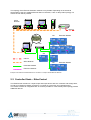
Ethernet Powerlink Networks.................................................................................................... 5
2.2
Controlled Node – EtherControl................................................................................................ 6
2.3
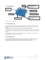
Construction .............................................................................................................................. 7
2.4
Processor unit ........................................................................................................................... 7
2.5
Periphery unit ............................................................................................................................ 7
Technical data .................................................................................................................................. 8
3.1
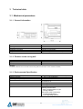
Mechanical parameters............................................................................................................. 8
3.1.1
General information ........................................................................................................... 8
3.1.2
Distance to the casing wall ................................................................................................ 8
3.1.3
Environmental Specification .............................................................................................. 8
3.1.4
Storage and transportation conditions ............................................................................... 9
3.1.5
Connectors......................................................................................................................... 9
3.2
Electrical parameters ................................................................................................................ 9
3.2.1
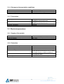
Supply of the module ......................................................................................................... 9
3.2.2
Protection........................................................................................................................... 9
3.2.3
Ethernet connection ......................................................................................................... 10
3.2.4
Binary inputs .................................................................................................................... 10
3.2.5
Binary outputs .................................................................................................................. 11
3.2.6
Analogue inputs ............................................................................................................... 12
3.2.7
Temperature sensor inputs (optionally) ........................................................................... 12
3.2.8
Analogue outputs ............................................................................................................. 13
3.2.9
Counter / Incremental inputs............................................................................................ 13
Installation ...................................................................................................................................... 14
4.1
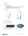
Mechanical setup .................................................................................................................... 14
4.2
Electrical installation................................................................................................................ 14
4.2.1
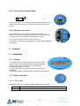
Connection of terminals A – D ......................................................................................... 14
4.2.2
Connection of power supply ............................................................................................ 15
4.2.3
Ethernet connectors......................................................................................................... 15
Controls .......................................................................................................................................... 15
5.1
Indicators................................................................................................................................. 15
5.1.1
Display ............................................................................................................................. 15
5.1.2
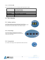
Status indicators .............................................................................................................. 15
5.1.2.1
Error LED.................................................................................................................. 15
5.1.2.2
STATUS LED ........................................................................................................... 16
5.2
User elements ......................................................................................................................... 16
5.2.1
Address switches ............................................................................................................. 16
5.2.2
Control keys ..................................................................................................................... 16
5.2.3
Contrast level ................................................................................................................... 16
Technical description...................................................................................................................... 17
6.1
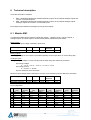
Module EM1 ............................................................................................................................ 17
6.2
Modul EM2 .............................................................................................................................. 18
Menu selection ............................................................................................................................... 18
7.1
Main menu .............................................................................................................................. 19
7.2
Display Inputs and Outputs ..................................................................................................... 20
7.3
Binary Input/Output simulation................................................................................................ 21
7.4
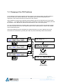
Changing of the CN IP address .............................................................................................. 22
7.5
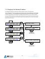
Changing of the Gateway IP address ..................................................................................... 23
7.6
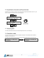
Specification of module and Powerlink data ........................................................................... 24
7.7
Show log data ......................................................................................................................... 24
7.8
Simulation enable.................................................................................................................... 24
Object dictionary............................................................................................................................. 25
8.1
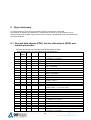
Process data objects (PDO), Service data objects (SDO) and module parameters .............. 25
8.2
PDO Mapping.......................................................................................................................... 29
2
SHFA-H-ETC-06CNM21-005-EN --all rights reserved