1
MTi and MTx User Manual and Tech. Doc., © 2006, Xsens Technologies B.V.
2.5 Calibrated data output mode
NOTE: This section is intended to give detailed information on the definition of the calibrated
inertial data output modes of the MTi and MTx. The output sequence of the elements of the
vectors defined here holds for all interface levels (RS-232/422, API, GUI). For more detailed
information about the respective interfaces please refer to their specific documentation;
Direct
Æ MTi and MTx Low-level communication Documentation
API
Æ MT Software Development Kit Documentation
GUI
Æ MT Software
2.5.1 Physical sensor model
This section explains the basics of the individual calibration parameters of each MTi and
MTx. This explains the values found on the MT Test and Calibration Certificate that
comes with each MTi and MTx.
The physical sensors inside the MTi and MTx (accelerometers, gyroscopes and
magnetometers) are all calibrated according to a physical model of the response of the sensors
to various physical quantities, e.g. temperature. The basic model is linear and according to the
following relation:
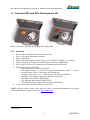
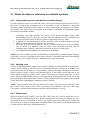
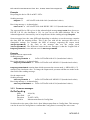
s = K T−1 ( u − bT )
The model really used is more complicated and is continuously being developed further. From
factory calibration each MTi / MTx has been assigned a unique gain matrix, KT and the bias
vector, bT This calibration data is used to relate the sampled digital voltages, u, (unsigned
integers from the 16 bit ADC’s) from the sensors to the respective physical quantity, s.
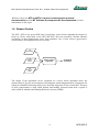
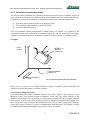
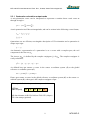
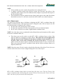
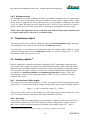
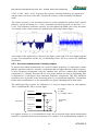
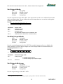
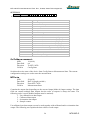
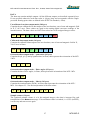
The gain matrix is split into a misalignment matrix, A, and a gain matrix, G. The
misalignment specifies the direction of the sensitive axes with respect to the ribs of the
sensor-fixed coordinate system (S) housing. E.g. the first accelerometer misalignment r1
describes the sensitive direction of the accelerometer on channel one. The three sensitive
directions are used to form the misalignment matrix:
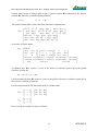
⎡
⎤
a1,x a1,y a 1,z
A = ⎣a2,x a2,y a 2,z ⎦
a3,x a3,y a 3,z
⎡
⎤
G1 0
0
G = ⎣ 0 G2 0 ⎦
0
0 G3
⎤⎡
⎤
⎡
G1 0
0
a1 ,x a1,y a1,z
KT = ⎣ 0 G 2 0 ⎦ ⎣a2 ,x a2,y a2,z ⎦ + O
0
0 G 3 a3 ,x a3,y a3,z
With O representing higher order models and temperature modelling, etc.
Each MTi and MTx is also modeled for temperature dependence of both gain and bias for all
sensors and other effects. This modeling is not represented in the simple model in the above
equations, but is implemented in the firmware.
13
MT0100P.G