1
USER’S MANUAL PHD02
2.2. Light receiver
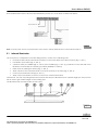
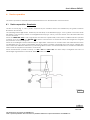
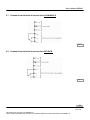
The receiver is usually fitted below the film sliding surface and consists of the following parts:
•
Receiving photodiode arrays for infrared, positioned along the reading axis and as long as the width of the
film to check
•
2 luminous LEDs [one GREEN and one RED ], positioned on the side wall of the receiver to identify the
operating condition (normal or micro-hole present)
•
Instrumentation amplifier circuit
•
Comparator circuit to detect micro-holes
•
Alarm output optoisolator to the PLC
•
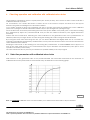
10-turn potentiometer to adjust the intervention threshold
In the event of drawn films, the format manufacturer should foresee a support-guide, which is as much adherent as
possible to the film lower part.
2.3. Gauge
On request a kit can be supplied which consists of three gauges with calibrated holes of:
1.
0.035 mm
2.
0.050 mm
3.
0.100 mm
both in the STANDARD version (+/- 10%) and in the version with metrological CERTIFICATE (+/- 2%).
They can be useful to periodically check the calibration of the receiver (intervention threshold – see Chpt. 6).
6
Rev. 1.00
This document is the property of LOGOMAT s.r.l.
Total or partial reproduction of this document is prohibited without the express authorization of LOGOMAT s.r.l..