1
RCX-LAN/Wi-Fi User Manual
V1.0 23-03-2011
WWW.QFP.IT
RCX-LAN/Wi-Fi User Manual
V1.0 23-03-2011 WWW.QFP.IT
INDICE
1. Hardware description ................................................................................................................................. 2
2. Technical Specifications ............................................................................................................................ 2
3. Getting Started ........................................................................................................................................... 3
3.1. Web-based Configuration Utility .......................................................................................................... 3
3.2. Follow the steps below to access the Web-based configuration utility. .............................................. 4
3.3. RCX-LAN/RCX-WI-FI operating modes .............................................................................................. 5
3.3.1. Modbus Gateway operating mode ................................................................................................ 5
3.3.2. Ethernet to Serial converter operating mode ................................................................................ 5
4. Configuration .............................................................................................................................................. 5
4.1. General Settings .................................................................................................................................. 5
4.2. Wi-Fi Settings ...................................................................................................................................... 6
4.3. Wi-Fi Status ......................................................................................................................................... 6
4.4. Routing Status ..................................................................................................................................... 7
4.5. Password ............................................................................................................................................. 7
4.6. Initialize ................................................................................................................................................ 8
4.7. Reboot ................................................................................................................................................. 8
4.8. Channel Settings ................................................................................................................................. 8
4.8.1. Modbus Gateway .......................................................................................................................... 8
4.8.2. Ethernet to Serial converter .......................................................................................................... 9
5. Status LED ............................................................................................................................................... 15
5.1. Status LED signals ............................................................................................................................ 15
5.1.1. Patterns that are played once in response to a certain event: ................................................... 15
5.1.2. Patterns that are played repeatedly until replaced by another pattern: ...................................... 15
6. I/O card .................................................................................................................................................... 16
6.1. Functions ........................................................................................................................................... 16
6.2. Variables ............................................................................................................................................ 16
6.3. Variable descriptions ......................................................................................................................... 17
6.3.1. ANALOG 1-4 ............................................................................................................................... 17
6.3.2. INPUTREG 1-2 ........................................................................................................................... 17
6.3.3. OUTREG 1-2 .............................................................................................................................. 17
6.3.4. COUNTER 1-5 ............................................................................................................................ 18
6.3.5. DEVICE....................................................................................................................................... 18
6.3.6. CONFIG ...................................................................................................................................... 18
6.3.7. SETTINGS .................................................................................................................................. 18
6.3.8. SLAVE ........................................................................................................................................ 18
6.3.9. RESET procedure ....................................................................................................................... 18
7. Quick Initialization .................................................................................................................................... 19
RCX-LAN/Wi-Fi User Manual
Page 1/19
RCX-LAN/Wi-Fi User Manual
V1.0 23-03-2011 WWW.QFP.IT
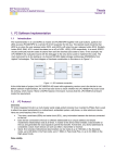
1. Hardware description
RCX-LAN/Wi-Fi is a Modbus RTU to Modbus TCP Gateway: allows you to connect devices using the
Modbus RTU protocol to an Ethernet / Wi-Fi using Modbus TCP protocol.
N°
1
2
3
4
5
6
7
8
9
10
11
12
13
14
15
16
17
18
19
20
21
22
23
24
N°
1
2
3
4
5
6
7
8
9
Identifier
L1
L2
L3
L4
L5
L6
L7
L8
L9
Identifier
AN1
AN2
AN3
GND
AN4
GND
GND
I/O1
I/O2
I/O3
I/O4
I/O5
+
NO1
NC1
CM1
NO2
NC2
CM2
V0
GND
B (-)
A (+)
Description
Analog input 1 (4-20mA)
Analog input 2 (4-20mA)
Analog input 3 (0-5V)
Ground
Analog input 4 (0-5V)
Ground
Ground
Digital input/output/counter 1
Digital input/output/counter 2
Digital input/output/counter 3
Digital input/output/counter 4
Digital input/output/counter 5
Positive supply
Negative supply
Normally open Relay 1
Normally close Relay 1
Common Relay 1
Normally open Relay 2
Normally close Relay 2
Common Relay 2
Output supply for external devices
Ground
RS-485 TX- (channel 2)
RS-485 TX+ (channel 2)
Descriptor
Relay 1 LED
Relay 2 LED
Digital input/output 1 status LED
Digital input/output 2 status LED
Digital input/output 3 status LED
Digital input/output 4 status LED
Digital input/output 5 status LED
Ethernet/Wi-Fi staus LED
I/O card activity LED
2. Technical Specifications
Below are the technical specifications of the RCX-LAN/Wi-Fi.
Technical Specifications:
Serial interface channel 1
RCX-LAN/Wi-Fi User Manual
IDC 20-pin male connector
Baud rate 300-115200 bps
Signals: TX, RX, CTS, RTS, DSR
Page 2/19
RCX-LAN/Wi-Fi User Manual
V1.0 23-03-2011 WWW.QFP.IT
RS-485 serial interface channel 2
Four-pole terminal block
Signals: TX+, TX-, V0, GND
Ethernet
10/100 Base-T Ethernet RJ45 connector
Protocols IP: TCP, UDP, ARP, ICMP, DHCP
Wi-Fi
IEEE 811.2b/g
WEP encryption 64/128 bit
Protocols IP: TCP, UDP, ARP, ICMP, DHCP
Configuration interface
WEB configuration
or provided configuration program
Security
Password
Analog inputs
4 inputs, A/D 10 bits converter, range:
4-20mA inputs 1 and 2
0-5V inputs 3 and 4
Digital I/O
5 digital I/O can be used:
Digital inputs (max voltage 30V)
Open collector outputs (load 100mA max 24V)
32 bits counter, non-volatile memory (max frequency 200Hz on
input 1, 10Hz on inputs 2-5)
Relay outputs
2 relè con contatti separati NO,NC portata 1A @ 125V Max
Status indicators
7 led status indicator I/O, 1 communication status indicator led, 1 Ethernet/WiFi status led
Power
RCX-LAN: 12V DC 160mA MAX (relays on) – 125mA (relays off)
RCX-Wi-Fi: 12V DC 195mA MAX (relays on) – 160mA (relays off)
Operating Environment
Temperatura da -20 a 70 C°, umidità relativa da 5% a 95%.
Size
95X53X58 mm (3 DIN modules)
Certification
CE, EN50082, EN55011 directives
3. Getting Started
This section will show you how to configure your new RXC-LAN/RCX Wi-Fi using the web-based
configuration.
3.1. Web-based Configuration Utility
Use the Web-based Configuration Utility if you wish to change the default settings or optimize the
performance of the RCX-LAN/RCX-WI-FI. After you have completed the initial installation, you can access
the configuration menu at any time by opening a web-browser and typing in the IP address of the RCXLAN/RCX-WI-FI. The RCX-LAN/RCX-WI-FI’s default IP address is 192.168.168.1.
RCX-LAN/Wi-Fi User Manual
Page 3/19
RCX-LAN/Wi-Fi User Manual
V1.0 23-03-2011 WWW.QFP.IT
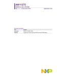
3.2. Follow the steps below to access the Web-based configuration utility
1. Open a web browser;
2. Type in the IP address of the RCX-LAN/RCX-WI-FI (192.168.168.1);
Note: If you have changed the default IP address assigned to the RCX-LAN/RCX-WI-FI, make sure
to enter the correct IP address.
1. Leave the Password field blank;
2. Click Login.
Note: The IP address of your pc must be in the same subnet as the RCX-LAN/RCX-WI-FI.
After logging in, the General Settings page will be displayed.
RCX-LAN/Wi-Fi User Manual
Page 4/19
RCX-LAN/Wi-Fi User Manual
V1.0 23-03-2011 WWW.QFP.IT
3.3. RCX-LAN/RCX-WI-FI operating modes
RCX-LAN/RCX-WI-FI has several modes of operation; it can be flexibly configured to operate as a Ethernet
to Serial converter or a Modbus TCP to Modbus RTU Gateway. Each RCX-LAN/RCX-WI-FI’s channel can be
configured to operate in both modes. In particular, Channel 0 is connected to the RS232 serial port, while
Channel 1 is connected to the RS485 serial port. Output to RS485 serial port is connected an I/O card,
designed for monitoring and remote control of technological systems, which allows it to be used as data
acquisition module Modbus RTU.
RCX-WI-FI has a Wi-Fi interface. It is through this interface that you find available Wi-Fi networks and select
the one to associate with. The device is compatible with the IEEE 811.2b/g. The protection of data on Wi-Fi
is provided by a 64/128 bit WEP encryption. You can also create an ad-hoc network of your own and have
other stations connect to it.
3.3.1.Modbus Gateway operating mode
Follow the steps below to configure RCX-LAN/RCX-WI-FI for Modbus Gateway operating mode.
3. In the General Settings page setting the parameters of the Ethernet network, namely IP-Address,
Subnet mask and Gateway IP-Address.
Note: The IP address of your pc must be in the same subnet as the RCX-LAN/RCX-WI-FI.
4. In the Channel Settings page choose the Channel and then select the TCP/IP transport protocol and the
Modbus Gateway routing mode. Also define the parameters of the serial connection, namely Port, Baud
rate, Parity and Slave Address.
5. The other parameters are defined according to their needs.
Now the device is configured to operate as a Modbus gateway.
Note: For details see section 4.8.2.
3.3.2.Ethernet to Serial converter operating mode
Follow the steps below to configure RCX-LAN/RCX-WI-FI for Ethernet to Serial converter operating mode.
1. In the General Settings page setting the parameters of the Ethernet network, namely IP-Address,
Subnet mask and Gateway IP-Address.
Note: The IP address of your pc must be in the same subnet as the RCX-LAN/RCX-WI-FI.
2. In the Channel Settings page choose the Channel and then choose one of the first three routing
mode options. Also define the parameters of the serial connection, namely Port, Baud rate, Parity
and Slave Address.
3. The other parameters are defined according to their needs.
Now the device is configured to operate as a Ethernet to Serial converter.
Note: For details see section 2.9.
4. Configuration
This section explain in detail all the parameters of the RCX-LAN/RCX-WI-FI. The parameters are divided into
configuration page.
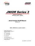
4.1. General Settings
Owner Name: defines the owner name identification for the RCX-LAN/RCX-WI-FI.
RCX-LAN/Wi-Fi User Manual
Page 5/19
RCX-LAN/Wi-Fi User Manual
V1.0 23-03-2011 WWW.QFP.IT
Device Name: defines the device name identification for the RCX-LAN/RCX-WI-FI.
DHCP: Choose Dynamic IP(DHCP) to obtain IP Address information automatically from server, then
for the DHCP to work there must be a DHCP server on the network where the RCX-LAN/RCX-WI-FI
is installed.
IP-Address: 192.168.168.1 is the default WAN IP Address of the RCX-LAN/RCX-WI-FI.
Subnet mask: 255.255.255.0 is the default subnet mask. All devices on the network must have the
same subnet mask to communicate on the network.
Gateway IP-Address: enter the IP Address of the gateway in your network. The default setting is
192.168.168.254.
Number of serial ports: defines the number of serial ports available.
4.2. Wi-Fi Settings
The Wi-Fi Settings page is used to configure the wireless settings for the RCX-LAN/RCX-WI-FI.
Wi-Fi: select enable if you want to switch on the Wi-Fi; the default value is disable.
SSID: the Wireless Network Name, also called the SSID, is a unique name that identifies a network.
All devices on a network must share the same wireless network name in order to communicate on
the network. If you decide to change the wireless network name from the default setting, enter your
new wireless network name in this field.
Domain: wireless communications and channels are tightly regulated in every country on Earth, and
this applies to Wi-Fi networks as well. Not every one of 14 pre-defined Wi-Fi frequencies is allowed
to be used in every country. It is your responsibility to set a correct "domain" for your Wi-Fi device.
This is done through the Domain. Supported domains are FCC, EU, JAPAN, and "OTHER". The
default value is EU: European Union.
TX Power: the output power of the Wi-Fi hardware can be adjusted in 12 steps. The power value
roughly corresponds to dB. The lowest output power is 4 and the highest power is 15. Lower power
reduces the current consumption of the Wi-Fi module, but not by much. The default power value is
15.
Authentication: select a wireless security setting. Options are None, WEP 64-bit or WEP 128-bit.
Select None to disable encryption to across the network. Select WEP 64bits or WEP 128bits to limit
communication to only those devices that share the same WEP settings.
Password WEP: A string containing new WEP key. This is a "HEX strings", each character in the
string represents one HEX digit. The string must contain 10 HEX digits for 64-bit WEP and 26 HEX
digits for 128-bit WEP. Excessive digits are ignored. Missing digits are assumed to be 0.
Ad-hoc Network: the Wi-Fi interface can create an ad-hoc network of its own and have other devices
associate with you.
Wi-Fi Channel: Channel on which the new ad-hoc network will operate.
Note: This section applies only to RCX-WI-FI.
4.3. Wi-Fi Status
This screen displays the current Wireless LAN settings on your RCX-LAN/RCX-WI-FI. The information in the
dialog is updated each time Refresh button is pressed.
Wi-Fi Status dialog displays the following information:
Wireless. In this section, there are information about the wireless LAN whose name appears in the
SSID domain:
o Wireless indicates the hardware Wi-Fi status: Enabled or Disabled.
RCX-LAN/Wi-Fi User Manual
Page 6/19
RCX-LAN/Wi-Fi User Manual
V1.0 23-03-2011 WWW.QFP.IT
o SSID contain the name of the target network.
o Status indicates whether the Wi-Fi interface is associated with the network or no.
o Strength indicates the strength of the signal received from the network.
o Authentication indicates the wireless network security setting.
o Wireless Channel contain the number of the channel on which this network operates.
Wi-Fi Networks. Wi-Fi Networks is the list of discovered wireless networks. For each network in the
list, on the right of the name as reported the strength of the signal received from this network.
Note: This section applies only to RCX-WI-FI.
4.4. Routing Status
This screen displays the current LAN settings on your RCX-LAN/RCX-WI-FI and the current RCX-LAN/RCXWI-FI operation. This feature is a very useful debugging tool that lets you determine the DS state at any
moment. The information in the dialog is updated each time Refresh button is pressed.
Routing Status dialog displays the following information:
Current state of routing buffers. Routing buffers are used as a temporary storage for the data
being routed between the Ethernet and serial ports of the Device Servers (DS). The routing status
dialog reports the number of committed bytes (for serial-->Ethernet buffer), total number of bytes in
each buffer ("data"), and the capacity of the buffers. Read serial-to-Ethernet data rounting topic to
learn what "committed" means. Capacity information is provided because different DS models have
buffers of different size.
Information on current data connection. This partially doubles the data reflected by the status
icons (displayed in the device list) and the status area of the main window. Additional information
provided by the routing mode dialog includes the IP-address and the port number of the network
host with which the DS has been/is/will be in a data connection. Here is what these two fields show:
o After power-up the fields show the IP-address and port defined by the Destination IPaddress setting and Destination Port Number setting;
o If these default values are overridden by serial-side parameters and instructions (a.k.a.
"modem commands") then the fields show new overriding values;
o While the data connection is established and after it is closed (aborted) the fields show the
IP-address and port of the network host with which this connection is (was) established.
Notice that this may be different from the above- if the DS has accepted an incoming
connection!
Current serial port setup. This data may be of interest because it will not necessarily match the
serial port setup defined by the serial port-related DS settings. The values of settings can be
overridden by the network-side parameters (a.k.a. "on-the-fly commands"). Therefore, the routing
status dialog can be used to verify actual current serial port setup.
Current state of RS232 control lines. The state of control lines is displayed in the opposite polarity.
So, if the state of RTS line (output) is shown as HIGH then this means that the DS is ready to
receive the data from attached serial device.
4.5. Password
The Password page is used to change the login password and the DS Manager password.
RCX-LAN/Wi-Fi User Manual
Page 7/19
RCX-LAN/Wi-Fi User Manual
V1.0 23-03-2011 WWW.QFP.IT
4.6. Initialize
The Initialize is used to reset the RCX-LAN/RCX-WI-FI: the device returns to factory default.
4.7. Reboot
The Reboot is used to take effect the changes.
4.8. Channel Settings
Each RCX-LAN/RCX-WI-FI’s channel can be configured to operate as a Modbus Gateway or a Ethernet to
Serial converter. In particular, Channel 0 is connected to the RS232 serial port, while Channel 1 is connected
to the RS485 serial port. Output to RS485 serial port is connected an I/O card, designed for monitoring and
remote control of technological systems.
4.8.1.Modbus Gateway
Connection Timeout: connection parameter sets the timeout (in minutes) for the data connections
between the VSP and the RCX-LAN/RCX-WI-FI. If no data is transmitted across the data connection
(TCP or UDP) for a specified number of minutes the VSP aborts the connection. Setting connection
timeout parameter to 0 disables the feature and connection never times out. If omitted, this
parameter defaults to 5 minutes.
Transport Protocol: selects which communications protocol- TCP/IP or UDP/IP will be used by the
VSP for data communications with the RCX-LAN/RCX-WI-FI. In the Gateway Modbus the
communications protocol is TCP/IP.
Routing Mode: select a mode operation of the RCX-LAN/RCX-WI-FI.
Accept connection from: defines whether the RCX-LAN/RCX-WI-FI will accept incoming data
connections from any network host (filtering disabled) or specific host only (filtering enabled).
o When Source IP Filtering is 0 (disabled) the RCX-LAN/RCX-WI-FI will accept an incoming
data connection from any network host.
o When Source IP Filtering is 1 (enabled) the RCX-LAN/RCX-WI-FI will accept an incoming
data connection only from host whose IP-address matches the one specified by current
Destination IP-address.
Port: defines the Data Port on which the RCX-LAN/RCX-WI-FI is accepting incoming data
connections. For TCP communications the RCX-LAN/RCX-WI-FI accepts incoming data connections
on the data port but establishes outgoing connections from a pool of ephemeral ports in the 1000010255 range (port number is incremented with each new connection). Port 65535 is excluded from
the allowable range because port 65535 is a programming port of the RCX-LAN/RCX-WI-FIcommand UDP datagrams are sent to this port. Technically, this only affects UDP communications,
TCP connections should still be able to use this port but the port 65535 was not allowed to be
selected as the data port from the early versions of RCX-LAN/RCX-WI-FI firmware so this restriction
is now preserved for "historical" reasons.
Slave Address: defines the address of the device on Modbus serial line. The default value is 191.
Serial Interface: serial port of the RCX-LAN/RCX-WI-FI can operate in full-duplex or half-duplex
mode. In the Gateway Modbus the value is half-duplex (RS485).
Baud rate: defines the baud rate of the serial port of the RCX-LAN/RCX-WI-FI.
RCX-LAN/Wi-Fi User Manual
Page 8/19
RCX-LAN/Wi-Fi User Manual
V1.0 23-03-2011 WWW.QFP.IT
Parity: defines the parity mode of the serial port of the RCX-LAN/RCX-WI-FI. RCX-LAN/RCX-WI-FI
hardware does not have an option of two stop bits. In the Gateway Modbus mode the default value is
“EVEN”.
Data bits: defines the bits/byte mode of the serial port of the RCX-LAN/RCX-WI-FI. The default value
is 8 bits/byte.
Maximum Intercharacter Delay: defines the maximum time gap between two consecutive characters
recorded into the serial-to-Ethernet buffer, exceeding which will trigger a break condition. Break
conditions are related to routing the data in the serial-to-Ethernet direction. Intercharacter delay can
be set in 10 ms increments. Delay tracking is disabled when Maximum Intercharacter Delay is set to
0.
Timeout RX: defines the timeout value of the serial port in Modbus Gateway mode. The value is in
milliseconds. The default value is 200ms for a value of baud rate of 9600bps . For lower baud rate is
preferable to use a longer timeout value.
4.8.2.Ethernet to Serial converter
Connection Timeout: defines after how many minutes an idle connection is terminated. Setting
Connection Timeout to 0 disables automatic timeouts. Setting Connection Timeout to any value in
the 1-99 range enables automatic timeouts: when no packets are transferred across a connection in
either direction for a corresponding number of minutes the connection is terminated. The device
terminates TCP connection by sending an RST packet, while UDP "connections" are simply
discarded (the other party is not informed in any way).
Connection Timeout prevents an idle ("hanged") connection from occupying the DS indefinitely thus
keeping other network hosts from communicating with the DS. Note, that idle connection is defined
as the one across which no packets are transferred for a period of time (not the one across which no
data is transferred for a period of time). This provides a way of maintaining the connection even in
the absence of data (this is known as "keepalive"). For TCP connections remote host can send
empty ACK packets, for UDP " connection " remote host can send UDP datagrams of zero length.
Connection Timeout is relevant even when the Connection Mode (CM) setting is 0 (immediately). In
this case, when timeout comes the DS terminates an existing connection to the network host and
immediately opens a new one. This can be used to "auto-repair" hanged connection in systems
where permanent connection to the network host must be maintained indefinitely.
Transport Protocol: selects which communications protocol- TCP/IP or UDP/IP will be used by the
VSP for data communications with the DS. Omitting the parameter selects the UDP/IP protocol.
For the data connection with the DS to work the same transport protocol must be selected on the DS
side. This parameter has the same function as the transport protocol option of the VSP for Windows.
Unless you have a specific reason why the UDP should be used (very rare!) we recommend you to
stick to the TCP/IP. The TCP/IP is a "reliable delivery" protocol that makes sure that no data is lost
"in transit" between the VSP and the DS. The UDP, on the contrary, does not guarantee data
delivery.
Broadcast UDP data: when Broadcast UDP is 1 (enabled), the DS will accept and route the data
received in broadcast UDP datagrams, as if these packets were addressed directly to this DS.
Broadcast packets must still be addressed to the correct Port Number. DS will ignore broadcast UDP
packets when Broadcast UDP is 0 (disabled). This setting only allows/disallows the reception of
broadcast UDP packets and has no influence over whether the DS can send out its own broadcast
UDP datagrams or not. This Setting is irrelevant when current Transport Protocol (TP) is 1 (TCP),
because TCP protocol cannot use broadcast packets to carry data.
RCX-LAN/Wi-Fi User Manual
Page 9/19
RCX-LAN/Wi-Fi User Manual
V1.0 23-03-2011 WWW.QFP.IT
Inband Command: setting defines whether inband (TCP) programming is enabled or disabled. This
Setting is irrelevant when the current Transport Protocol is 0 (UDP) because inband command
passing is only possible when TCP/IP is used for data connections between the network host and
the DS.
Routing Mode: select a mode operation of the RCX-LAN/RCX-WI-FI. Routing Mode drop-down box
provides four choices:
o Server. Only incoming connections are accepted, the VSP never attempts to establish an
outgoing connection to the DS. There is no restriction on which DS can connect to the VSPconnection from any IP-address will be accepted as long as the DS is connecting to the
correct listening port using correct transport protocol.
o Server/client. Both incoming and outgoing connections are allowed. Outgoing connections
are established with the destination, specified in the destination section of the dialog. Exactly
when the VSP attempts to establish an outgoing connection is defined by the selected
connection mode. Incoming connections are accepted from any IP-address, just like with the
server routing mode.
o Client. Only outgoing connections are allowed, the VSP rejects all incoming connections.
o Gateway Modbus.
Destination interface: selects the network interface through which an outgoing network connection
will be established (Note: This parameter is used only in RCX-WI-FI).
Accept connection from: defines whether the RCX-LAN/RCX-WI-FI will accept incoming data
connections from any network host (filtering disabled) or specific host only (filtering enabled).
o When Source IP Filtering is 0 (disabled) the RCX-LAN/RCX-WI-FI will accept an incoming
data connection from any network host.
o When Source IP Filtering is 1 (enabled) the RCX-LAN/RCX-WI-FI will accept an incoming
data connection only from host whose IP-address matches the one specified by current
Destination IP-address.
This setting is irrelevant when current Routing Mode is 2 (client) because in this mode the DS won't
accept incoming connections at all.
Port: this setting defines the Data Port on which the DS is accepting incoming data connections. For
UDP communications, outgoing UDP datagrams are also sent from this port. For TCP
communications the DS accepts incoming data connections on the data port but establishes
outgoing connections from a pool of ephemeral ports in the 10000-10255 range (port number is
incremented with each new connection). Port 65535 is excluded from the allowable range because
port 65535 is a programming port of the DS- command UDP datagrams are sent to this port.
Technically, this only affects UDP communications, TCP connections should still be able to use this
port but the port 65535 was not allowed to be selected as the data port from the early versions of DS
firmware so this restriction is now preserved for "historical" reasons. Since programming UDP
datagrams can now also be sent to port 32767, this port cannot be used for UDP data
communications when current Transport Protocol is 0 (UDP). The DS will allow the Port Number to
be programmed to 32767 but all data sent to this port in the UDP mode will be interpreted as
programming commands. Using port 32767 for TCP communications won't cause any problems.
New telnet programming method uses telnet port 23 for DS programming as well. Any connection
established to port 23 of the DS is interpreted by the DS as a programming connection. Therefore,
this port cannot be used for data connections when the current Transport Protocol is 1(TCP).
Connection Mode: defines under which condition the DS attempts to establish an outgoing
connection (Since the DS only allows for a single data connection at a time all conditions described
here only apply to a situation when no data connection is established yet) to current Destination IPaddress and current Destination Port Number:
RCX-LAN/Wi-Fi User Manual
Page 10/19
RCX-LAN/Wi-Fi User Manual
V1.0 23-03-2011 WWW.QFP.IT
o
0 (immediately). The DS attempts to establish an outgoing connection right after the power
up (After the IP-address is obtained from the DHCP server if the DHCP setting is 1
(enabled)). The DS will also make this connection "persistent". If the connection is closed
(aborted) by the network host the DS will (attempt to) establish it again. Connection timeout
(defined by the Connection Timeout (CT) setting) still works in this mode: when the current
connection times out the DS aborts it and immediately establishes a new connection. Such
behavior "auto-repairs" hanged connections.
o 1 (on data or command). The DS attempts to establish an outgoing connection when the first
serial data is received into the serial port and committed OR when Establish Connection
instruction is issued.
o 2 (on command). The DS attempts to establish an outgoing connection only when Establish
Connection instruction is issued.
o 3 (on command or DSR=LOW). The DS attempts to establish an outgoing connection only
when Establish Connection instruction is issued OR when the DSR line of the serial port is
brought LOW (for at least 20ms).
Existing connection can always be terminated by using the Close Connection instruction or Abort
Connection instruction. With Connection Mode 3 (on command or DSR=LOW) it is also possible to
close the connection by bringing the DSR line HI. Connection Mode is irrelevant when the current
Routing Mode is 0 (server) since in this mode outgoing connections are not allowed at all.
Destination IP-address: Defines the IP-address of the destination network host to which the DS will
attempt to connect to (by default). Destination IP-address serves two purposes:
o It defines the IP-address of the network host to which the DS will attempt to establish an
outgoing data connection. Exactly when the DS will attempt to establish such a connection is
specified by the Connection Mode setting. Destination port the DS will attempt to connect to
is specified by the current Destination Port Number.
o This address also specifies the only network host from which an incoming data connection
will be accepted when current Source IP Filtering is 1 (enabled).
Destination IP-address is irrelevant in the following cases:
o For outgoing connection when current Routing Mode is 0 (server) because the DS does not
establish outgoing connections in this mode at all.
o For incoming connections when current Routing Mode is 2 (client) because the DS does not
accept any incoming connections in this mode at all or when current Source IP Filtering is 0
(disabled).
Destination Port: Destination Port Number defines the port of the network host to which the DS will
attempt to establish an outgoing connection. When the DS will attempt to establish a connection to
the destination host is defined by the Connection Mode setting. Destination IP-address the DS will
attempt to connect to is defined by the current Destination IP-address. Destination Port Number is
irrelevant when the current Routing Mode is 0 (server) since in this mode outgoing connections are
not allowed.
Notification Destination: defines which UDP port the DS will send I/O line status change notifications
to. Notification messages are generated when one of the monitored I/O lines of the DS changes its
state. Which I/O lines are monitored for changes is defined by the Notification Bitmask setting.
Notifications are only sent when the data connection is established and are sent to the network host
with which this connection is established. Notification Destination defines which UDP port on the
destination host notifications are sent to when notifications are being sent as UDP datagrams (outof-band):
o 0 (last know port). Notifications are sent to the UDP port from which the most recent
programming UDP datagram was received. Therefore, notifications are sent after at least
RCX-LAN/Wi-Fi User Manual
Page 11/19
RCX-LAN/Wi-Fi User Manual
V1.0 23-03-2011 WWW.QFP.IT
one such datagram is received (since the data connection is established). This option is
useful when the DS has to send notifications to the PC. Port number from which PC
applications are sending their programming UDP datagrams are usually ephemeral which
means that they are always changing. Therefore, the DS will wait for the first programming
UDP datagram to arrive.
o 1 (port 65535). Notifications are always sent to the UDP port 65535. This option is useful
when the DS is communicating with another DS. In this case the port to send notifications to
is fixed and known so there is no need to wait for the programming UDP datagram to arrive.
Notification Destination is irrelevant when the Notification Bitmask is set to is 0 because this means
that no I/O lines of the DS are monitored for changes (so there will be no notifications to generate).
Notification Destination is also irrelevant when notifications are being sent inside the data TCP
connection itself.
Serial Interface: serial port of the DS can operate in full-duplex or half-duplex mode. "Full-duplex"
and "half-duplex" here refers exclusively to the logical operation of the DS, not to the hardware
implementation of the serial port, which depends on the DS model. The setting only influences the
operation of the serial port in the data routing mode. When the serial port is in the serial
programming mode it is always using the half-duplex interface.
o 0 (full-duplex). Suitable for RS232 communications. RTS (output) and CTS (input)
lines are used in a "normal" way i.e. for flow control between the DS and attached
serial device (when current Flow Control = 1 (enabled)), or signaling between the
network host and attached serial device.
o 1 (half-duplex). Suitable for RS485 communications. In this mode the RTS line
provides direction control and the CTS line is unused. When the Ethernet-to-serial
buffer of the DS is empty (nothing to send out through the serial port) the RTS line is
LOW. When there is some data to send out the RTS line is HI for as long as the data
is being output. Such behavior is intended to allow the RTS line to control the
direction pin of the RS485 interface ICs and RS232-to-RS485 converters.
Flow Control: enables or disables hardware (RTS/CTS) flow control for the serial port of the DS
(when in the data routing mode). When the Flow Control is 0 (disabled) the status of the CTS input is
ignored and the RTS line is at LOW unless changed by the remote host. When the Flow Control is 1
(enabled) the RTS (output) and CTS (input) lines are used to regulate the flow of data across the
serial cable connecting the DS to the attached serial device.
o RTS is used to regulate the flow of data from the attached serial device to the DS.
When the serial-to-Ethernet buffer of the DS has free space the RTS is LOW and the
serial device is free to send the data. When the buffer becomes (almost) full the DS
sets the RTS line to HI thus telling the serial device to stop sending the data. The
RTS is set to HI when there are less than 20 free bytes left in the serial-to-Ethernet
buffer. Additionally, the RTS line is set to HI in all cases when the serial port is
closed.
o CTS is used to regulate the flow of data from the DS to the attached serial device.
As long as the DS detects LOW on its CTS input it is free to send out the data to the
attached serial device. To stop the DS from sending out the data, the serial device
must set the CTS line to HI. The DS won't send out the data for as long as it detects
HI on its CTS input.
Flow Control is irrelevant when the current serial interface is half-duplex.
DTR Mode: Defines the function of the DTR line of the serial port of the DS. When the DTR Mode is
0 (idle) the DTR line is at LOW unless changed by the remote host. When the DTR Mode is 1
(connection status) the DTR (output) line of the DS reflects current connection status: the DTR line is
RCX-LAN/Wi-Fi User Manual
Page 12/19
RCX-LAN/Wi-Fi User Manual
V1.0 23-03-2011 WWW.QFP.IT
HI when no data connection is established at the moment and LOW when there is a data connection
in progress.
Power up DTR State: Defines High or Low state of DTR pin on Startup. This setting defines the
startup voltage of the DTR pin. By default, DTR is HI on startup. By changing this setting, you can
have DTR set to LOW on startup.
Baud rate: defines the baud rate of the serial port of the DS.
Parity: defines the parity mode of the serial port of the DS. DS hardware does not have an option of
two stop bits. The way around this is to set the Parity to 3 (mark). Since this means that the parity bit
will always be set to 1 and since the parity bit is always transmitted in front of the stop bit, this will
have the same result as having two stop bits. The DS transmits the serial data with the parity bit
correctly set but does not verify correctness of parity bits in the received data. Parity is always off
when the serial port is in the serial programming mode.
Data bits: defines the bits/byte mode of the serial port of the DS (when in the data routing mode). 8
bits/byte are always used when the DS is in the serial programming mode.
Maximum Intercharacter Delay: defines the maximum time gap between two consecutive characters
recorded into the serial-to-Ethernet buffer, exceeding which will trigger a break condition. Break
conditions are related to routing the data in the serial-to-Ethernet direction. See serial-to-Ethernet
data routing for more information. Intercharacter delay can be set in 10 ms increments. Delay
tracking is disabled when Maximum Intercharacter Delay is set to 0. Intercharacter delay is not
counted when the Flow Control setting is 1 (enabled) and the DS is holding the RTS line in the HI
state thus indicating to the attached serial device that the DS is not ready to receive the data. This is
done to prevent the DS from generating the break conditions on time gaps caused by the DS itself.
Soft entry into Serial programming mode: Disables or enabled serial programming mode entry
through escape sequence and selects escape sequence type.
o 0 (disabled). Serial programming mode entry through escape sequence is disabled.
o 1 (type 1). Type 1 escape sequence consists of three consecutive escape characters (ASCII
code of escape character is defined by the Escape Character setting). For the escape
sequence to be recognized each of the escape characters must be preceded by a time gap
of at least 100ms:
...previous data <--100ms--> E.C. <--100ms--> E.C. <--100ms--> E.C.
If the time gap before a certain escape character exceeds 100ms then this character is
considered to be a part of the escape sequence and is not recorded into the serial-toEthernet buffer. If the time gap before a certain escape character is less than 100ms than
this character is considered to be a normal data character and is saved into the serial-toEthernet buffer. Additionally, escape character counter is reset and the escape sequence
must be started again. The following example illustrates one important point (escape
characters are shown as ). Supposing, attached serial device sends the following string:
ABC <--100ms--> <--100ms--> DE
First two escape characters is this example had correct time gap before them, so they were
counted as a part of the escape sequence and not saved into the buffer. The third escape
character did not have a correct time gap so it was interpreted as a data character and
saved into the buffer. The following was routed to the network host:
ABC DE
The side effect and the point this example illustrates is that first two escape characters were
lost- they neither became a part of a successful escape sequence (because this sequence
wasn't completed), nor were saved into the buffer.
RCX-LAN/Wi-Fi User Manual
Page 13/19
RCX-LAN/Wi-Fi User Manual
V1.0 23-03-2011 WWW.QFP.IT
o
2 (type 2). Type 2 escape sequence is not based on any timing. Escape sequence consists
of escape character (defined by the Escape Character setting) followed by any character
other than escape character. To send a data character whose ASCII code matches that of
escape character the serial device needs to send this character twice. This will result in a
single character being saved into the serial-to-Ethernet routing buffer. It is the responsibility
of the serial device to parse through the data it sends to the DS and "double" all characters
whose code matches that of escape character. Example: the following sequence will make
the DS enter the serial programming mode (that is, if current escape character is not 'D'):
ABC D
In the sequence below two consecutive escape characters will be interpreted as data (data
routed to the network host will contain only one such character- the DS will automatically
eliminate the second one):
ABC
It should be noted that attached serial device should parse the data and double certain
characters only for the data it sends to the DS. Reverse operation is not needed for the data
being received by the serial device from the DS. Characters with ASCII code matching that
of escape character arrive from the DS in a normal way- i.e. they are not "doubled".
Notice, that serial escape sequence works even when the serial port of the DS is closed (i.e. when
the Current Routing Mode is 0 (Slave) and the data connection is not established). "Closed" merely
means that the serial port is not accepting any data into its serial-to-network buffer. The serial port is
still listening for escape sequences even at this time. When the DS is running with the Flow Control
setting set to 1 (Local) and its serial port is "closed", the RTS line of the DS will be in the disabled
state (thus indicating to attached serial device that transmission is not allowed). Therefore, if the
serial device needs to transmit an escape sequence it must ignore the state of RTS signal at that
time. Further behaviour of the RTS line while in serial programming mode is documented under
Serial Programming.
Escape Character: defines the ASCII code of character used in escape sequence. Which escape
sequence, if any, is used is defined by the Soft Entry setting. Escape Character is irrelevant when
the Soft Entry setting is 0 (disabled).
On-the-Fly command: enables or disables on-the-fly command processing by the DS. When On-theFly command setting is 1 (enabled) the DS will accept on-the-fly command (network-side parameters
and instructions) from the network host. When On-the-Fly command setting is 0 (disabled) the DS
will reject on-the-fly command from the host. On-the-Fly command do not require prior authentication
through Login command. Password protection specifically for on-the-fly command can be enabled
through the On-the-Fly Password setting. On-the-Fly command provide a way of remotely controlling
the serial port of the DS, hence, the name of this setting- "Remote Control".
Password for on-the-Fly command: enables or disables password protection for on-the-fly
commands. On-the-fly commands do not require prior authentication through Login command. When
On-the-fly Password is 1 (enabled) and the Password setting is set (not <NULL>) the network host
must supply a valid password with every Parameter command it sends. On-the-fly Password is
irrelevant when the On-the-fly Commands setting is 0 (disabled) because in this case the DS doesn't
accept on-the-fly commands at all.
Notification Bitmask: defines which I/O lines of the DS are monitored for changes. When the line
being monitored changes its state a Notification message is generated and sent to the network host
with which the DS has an established data connection. Notification Bitmask is a byte value each bit
of which disables (when 0) or enables (when 1) status change monitoring for a specific I/O line.
RCX-LAN/Wi-Fi User Manual
Page 14/19
RCX-LAN/Wi-Fi User Manual
V1.0 23-03-2011 WWW.QFP.IT
5. Status LED
The RCX-LAN/RCX-WI-FI has one status GREEN LED: on top of the Device. It is controlled by the internal
circuitry.
5.1. Status LED signals
RCX-LAN/RCX-WI-FI feature one status LED -Status Green (SG)- that shows various states of device
operation. RCX-LAN/RCX-WI-FI states are indicated by way of playing "LED patterns". Patterns in this topic
are represented graphically in the following manner:
The pattern above means that green status LED blink together three times. The following pattern means
that green LED makes one long blink followed by two short ones:
Status LED of the RCX-LAN/RCX-WI-FI shows a number of conditions: listed below are all patterns.
5.1.1.Patterns that are played once in response to a certain event:
Powerup pattern. This pattern is displayed once when the RCX-LAN/RCX-WI-FI is switched on:
5.1.2.Patterns that are played repeatedly until replaced by another pattern:
Idle pattern. This pattern is displayed repeatedly when the RCX-LAN/RCX-WI-FI is in stand-by:
Connection Channel 0 (RS232). This pattern is displayed repeatedly when connection is
established on Channel 0:
Connection Channel 1 (RS485). This pattern is displayed repeatedly when connection is
established on Channel 1:
Connections Channel 0 and Channel 1. This pattern is displayed repeatedly when connections are
established on Channel 0 and Channel 1:
Error Mode. This pattern is displayed repeatedly at high speed.
Serial programming Mode. This pattern is displayed repeatedly at slow speed.
Sending ARP. Displayed when the RCX-LAN/Wi-Fi is sending ARP requests to find out MACaddress of the destination network host with which the RCX-LAN/Wi-Fi is about to establish a
connection:
Wi-Fi Enable. This pattern is displayed repeatedly when Wi-Fi is enabled, but it is not associated:
Note: This pattern applies only to RCX-WI-FI.
RCX-LAN/Wi-Fi User Manual
Page 15/19
RCX-LAN/Wi-Fi User Manual
V1.0 23-03-2011 WWW.QFP.IT
Wi-Fi Associated. This pattern is displayed repeatedly when Wi-Fi is associated:
Note: This pattern applies only to RCX-WI-FI.
6. I/O card
I/O card is designed for monitoring and remote control of technological systems. Through this card, you can
read the status of the appliances and check the same via PC software or devices such as PLC with Modbus
interface and intelligent terminals.
6.1. Functions
The available functions are:
0x03: Read Holding Register
0x04: Read Input Register
0x10: Preset Multiple Register
6.2. Variables
Below is a list of Modbus registers (Holding Registers / Input registers).
HEX
0x00
0x01
0x02
0x03
0x04
0x05
0x06
0x07
0x08
0x0A
0x0C
0x0E
0x10
0x100
0x101
0x102
0x103
DEC
0
1
2
3
4
5
6
7
8
10
12
14
16
256
257
258
259
WORD
1
1
1
1
1
1
1
1
2
2
2
2
2
1
1
1
1
RCX-LAN/Wi-Fi User Manual
TYPE
INT16
INT16
INT16
INT16
INT16
INT16
INT16
INT16
INT16
INT32
INT32
INT32
INT32
INT16
INT16
INT16
INT16
ACCESS
R
R
R
R
R
R
R/W
R/W
R/W
R/W
R/W
R/W
R/W
R
R/W
R/W
R/W
VARIABLE NAME
ANALOG 1
ANALOG 2
ANALOG 3
ANALOG 4
INPUTREG1
INPUTREG2
OUTREG1
OUTREG2
COUNTER1
COUNTER2
COUNTER3
COUNTER4
COUNTER5
DEVICE
CONFIG
SETTINGS
SLAVE
DESCRIPTION
Analog input 1
Analog input 2
Analog input 3
Analog input 4
Digital inputs 17-32
Digital inputs 1-16
Digital outputs 17-32
Digital outputs 1-16
Counter 1
Counter 2
Counter 3
Counter 4
Counter 5
Device information
Device configuration
Serial settings
Slave address
Page 16/19
RCX-LAN/Wi-Fi User Manual
V1.0 23-03-2011 WWW.QFP.IT
6.3. Variable descriptions
6.3.1.ANALOG 1-4
Read-only registers represents the value read from analog to digital converters. The value is expressed in
DAC units of 10 bit and is between 0 and 1023. For inputs 1 and 2 the value expressed in mA is given by this
formula:
mA = DAC/1024*5/100*1000 = DAC/20,48
Where:
DAC is the value contained in the register AnalogX.
As for inputs 2-3 the value expressed in volts is:
V = DAC/1024*5 = DAC/204,8
Where:
DAC is the value contained in the register AnalogX.
6.3.2.INPUTREG 1-2
Represent the state of digital inputs. Every bit of these registers corresponds to a digital input, the
correspondence is given by the following table:
Register
INPUTREG2
INPUTREG2
INPUTREG2
INPUTREG2
INPUTREG2
INPUTREG2
INPUTREG1
Bit
1
2
3
4
5
6-16
17-32
Input
INPUT IN1
INPUT IN2
INPUT IN3
INPUT IN4
INPUT IN5
UNUSED
UNUSED
The bit corresponding to the digital input is 1 if the input voltage exceeds 2.5 V cc, is 0 if the voltage is below
this threshold. To use the I / O as inputs, the corresponding bit in the registers OUTREGx, must be set to 0.
6.3.3.OUTREG 1-2
Represent the state of outputs. Every bit of these registers corresponds to a output, the correspondence is
given by the following table:
Register
OUTREG2
OUTREG2
OUTREG2
OUTREG2
OUTREG2
OUTREG2
OUTREG2
RCX-LAN/Wi-Fi User Manual
Bit
1
2
3
4
5
6
7
Input
OPEN COLLECTOR OUTPUT O1
OPEN COLLECTOR OUTPUT O2
OPEN COLLECTOR OUTPUT O3
OPEN COLLECTOR OUTPUT O4
OPEN COLLECTOR OUTPUT O5
RELAY R1
RELAY R2
Page 17/19
RCX-LAN/Wi-Fi User Manual
V1.0 23-03-2011 WWW.QFP.IT
OUTREG2
OUTREG1
8-16
17-32
UNUSED
UNUSED
For open collector output, when the corresponding bit is 1 the output transistor is closed to ground, while,
when the bit is 0, the transistor is open.
For relay outputs, 1 corresponds to the relay ON, 0 corresponds to the relay OFF.
6.3.4.COUNTER 1-5
Represent the 32 bit value of counters associated with the digital inputs. Input 1 can acquire a signal pulse
with a frequency of 100 Hz, while for inputs 2-5, the maximum frequency for the correct count is 10 Hz.
6.3.5.DEVICE
Reserved.
6.3.6.CONFIG
Reserved
6.3.7.SETTINGS
Setting the serial communication according to the following table:
1200
2400
4800
9600
19200
N,8,1
1
2
3
4
5
N,8,2
257
258
259
260
261
E,8,1
769
770
771
772
773
O,8,1
1793
1794
1795
1796
1797
For example, to set the serial port to 19200, N, 8,1 write 5 in the SETTINGS register.
6.3.8.SLAVE
Slave address of the device is programmable between 1 and 147 (191 default).
6.3.9.RESET procedure
At any time you can return the instrument to the factory settings.
Just hold down the NET button for 10 seconds, the NET LED starts flashing. If you continue to hold the
button for 10 seconds, restores factory settings.
In particular:
Slave address: 191;
Serial communication parameters: 9600, E, 8,1.
RCX-LAN/Wi-Fi User Manual
Page 18/19
RCX-LAN/Wi-Fi User Manual
V1.0 23-03-2011 WWW.QFP.IT
7. Quick Initialization
Quick initialization is a way to completely reinitialize the DS without using any commands. This feature is
handy when the DS is running in the error mode and needs to be repaired.
To quick-initialize the DS:
1. Make sure the DS is powered;
2. Press and release the Setup button to enter the serial programming mode. Status LED will play the
serial programming mode pattern;
3. Wait for at least three seconds;
4. Press and hold the Setup button for at least three seconds- both status LED will be switched off and
this will indicate that the initialization has been started;
5. Initialization takes about one second to complete. Initialization result will be shown by the status
LED- green LED will be switched on for about 2 seconds indicating successful initialization. (If the
red LED is switched on this means that the DS is malfunctioning).
6. Switch the DS off and back on again to exit the error mode if necessary.
RCX-LAN/Wi-Fi User Manual
Page 19/19