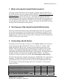
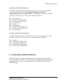
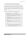
1
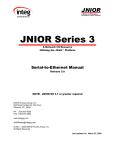
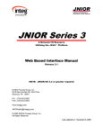
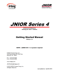
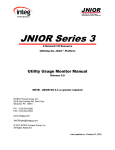
JNIOR Series 3 A Network I/O Resource Utilizing the JAVA Platform Serial Control PLUS Manual Release 4.2 NOTE: JNIOR OS 3.1 or greater required INTEG Process Group, Inc. 2919 East Hardies Rd, First Floor Gibsonia, PA 15044 PH (724) 933-9350 FAX (724) 443-3553 www.integpg.com [email protected] © 2012 INTEG Process Group, Inc. All Rights Reserved Last updated on: June 12, 2012 INTEG Process Group, Inc. TABLE OF CONTENTS 1 2 3 4 5 6 7 8 9 10 What is the Serial Control PLUS Function? ............................................................... 3 The Purpose of the Serial Control PLUS Function ..................................................... 3 Connecting a Serial Device ......................................................................................... 3 Connecting an Ethernet Device .................................................................................. 4 Enabling the Serial Control PLUS Software .............................................................. 5 Installing the Serial Control PLUS Software .............................................................. 6 Configuring the Serial Control PLUS Software ......................................................... 7 Serial Control PLUS Commands ................................................................................ 9 Testing Serial Control PLUS with Your JNIOR....................................................... 12 Options ...................................................................................................................... 14 JNIOR A Network I/O Resource Serial Control PLUS Manual – Release 4.2 2 INTEG Process Group, Inc. 1 What is the Serial Control PLUS Function? The Serial Control PLUS function for the JNIOR is a software application that runs on the JNIOR and allows the user to interact with the JNIOR I/O via the serial port and/or an Ethernet connection. (Serial Control PLUS is an enhanced version of the Serial Control program that only worked via the serial port. This manual still applies to the Serial Control program with the exception of the Ethernet connection and a few functions.) The user can control the relay outputs (on, off, pulse), receive the status of the digital inputs (on, off) and receive the counter values. The user can interact with the JNIOR I/O via the serial port and the Ethernet port at the same time. 2 The Purpose of the Serial Control PLUS Function The Serial Control PLUS function can be used in applications where the user’s external device cannot communicate over the Ethernet, but can communicate via an RS232 port. Or the device has an Ethernet port, but does not have a driver for the JNIOR protocol or Modbus protocol. The user’s device must be able to send simple ASCII commands to the JNIOR as defined later in this manual. 3 Connecting a Serial Device The default port for connecting a serial device is the Auxiliary Serial (AUX Serial) port located along the top edge of the JNIOR. (Please see “Section 10 – Options” of this manual for using the “RS-232 only” serial port located along the lower edge of the JNIOR.) There are two different physical connection types available for the Auxiliary Serial port. The JNIOR model number JNR-100-003B has a DB9 connector and the older JNIOR model number JNR-100-003A has a 5-pin connector. For both models, the auxiliary serial port can communicate via RS232, RS422 or RS485. The mode is configured via jumpers internal to the JNIOR. The default jumper setting is RS232. The following information is from the drawing titled – JNIOR Model 310 Connections & Mounting – available on the INTEG website, JNIOR downloads area. To modify the communication mode, you must remove the four screws on the JNIOR and remove the lid. The jumpers are located in the upper right corner. Pin number 1 is closest to the outside of the box. Mode RS-485 2-Wire Half Duplex – Terminated RS-485 2-Wire Half Duplex – Not Terminated RS-422/RS-485 4-Wire Terminated RS-422/RS-485 4-Wire Not Terminated RS-232 (default setting since January 1, 2008) JNIOR A Network I/O Resource Serial Control PLUS Manual – Release 4.2 J15 1–2 1–2 2–3 2–3 2–3 J16 1–2 1–2 2–3 2–3 2–3 J17 1–2 2–3 1–2 2–3 2–3 3 INTEG Process Group, Inc. Auxiliary Serial Port DB9 Connector For JNIOR model number JNR-100-003B, the serial device is connected to the DB9 connector typically using a standard, straight through serial cable when communicating with a PC or similar device. A null modem cable may be needed for certain types of other devices. The pin connections are as follows: Pin 1 – No connection Pin 2 – RS232 (TX) / RS485 (TX-) Pin 3 – RS232 (RX) / RS485 (RX-) Pin 4 – No connection Pin 5 – Ground Pin 6 – No connection Pin 7 – RS232 (RTS) / RS485 (RX+) Pin 8 – RS232 (CTS) / RS485 (TX+) Pin 9 – No connection Auxiliary Serial Port 5-Pin Connector For JNIOR model number JNR-100-003A, the serial device is connected to the 5-pin connector as follows, where pin 1 is closest to the center of the JNIOR box: Pin 1 – Ground Pin 2 – RS232 (TX) / RS485 (TX-) Pin 3 – RS232 (RTS) / RS485 (TX+) Pin 4 – RS232 (RX) / RS485 (RX-) Pin 5 – RS232 (CTS) / RS485 (RX+) 4 Connecting an Ethernet Device When the JNIOR is on an Ethernet network, any device on the network can send the ASCII commands to the JNIOR. The default port on the JNIOR that is listening for the commands is 9202. The user can change this port via the Registry Editor tab on the JNIOR Web page. JNIOR A Network I/O Resource Serial Control PLUS Manual – Release 4.2 4 INTEG Process Group, Inc. 5 Enabling the Serial Control PLUS Software The Serial Control or Serial Control PLUS software is pre-installed on all JNIORs. The version installed depends on when your JNIOR was manufactured. To activate the software so that it runs on boot up, please launch the main JNIOR web page, go to the Applications tab and check the Serial Control box. When finished, click the Save button and you will be asked if you want to reboot the JNIOR now. Please click “Yes” (if you are ready) and the JNIOR will reboot. After the reboot, the Serial Control software will be running. If you have an older JNIOR and want to utilize the Ethernet connection, then you must upgrade to the Serial Control PLUS software as described next section. JNIOR A Network I/O Resource Serial Control PLUS Manual – Release 4.2 5 INTEG Process Group, Inc. 6 Installing the Serial Control PLUS Software The Serial Control PLUS software is available from the INTEG website on the JNIOR downloads page. Please download the ‘All-in-One Update’ project that will be used with the JNIOR Support Tool. Do NOT unzip the update project. The JNIOR Support Tool will unzip it. On the Update tab in the JNIOR Support Tool, click Open Project and navigate to where you saved the All-in-One Update project zip file. Once the update project is displayed, you can leave all the steps checked and do a complete update of your JNIOR or you can uncheck them all except for the Update Serial Control PLUS step. Then click Publish Update to JNIOR and select your JNIOR from the pop-up box. NOTE: You will still need to do the previous step in Section 5 to enable the software to run and reboot the JNIOR so that the latest version is used. JNIOR A Network I/O Resource Serial Control PLUS Manual – Release 4.2 6 INTEG Process Group, Inc. 7 Configuring the Serial Control PLUS Software Once the Serial Control PLUS program is running, it will be ready to accept clients on the auxiliary serial port or via an Ethernet connection over port 9202. The default setting for the AUX serial port is 9600 baud, 8 data bits, 1 stop bit, no parity and flow control set to none. This means that the serial device connected to the JNIOR serial port must work with the above serial settings otherwise you will have to change the settings on either the JNIOR or your device. The Registry Editor tab on the JNIOR Main Web page can be used to change any settings for the Serial Control PLUS software program. After you enable the Serial Control PLUS program and it is running after a reboot, the default settings are displayed in the Registry Editor and are as shown below: JNIOR A Network I/O Resource Serial Control PLUS Manual – Release 4.2 7 INTEG Process Group, Inc. To modify any of the above Registry Keys, click on the appropriate key and then the Edit Key button. Make any changes and click the Save button. Your change will be saved. You must reboot the JNIOR for your changes to take effect. NOTE: Please do not pull the power after making your changes. You should do a ‘soft’ reboot of the JNIOR by going to the About tab in the JNIOR web page and clicking the reboot button. Registry Key Baud Default 9600 DataBits FlowControl 8 0 IncomingTermination String \r OutgoingTermination String \r PacketSize 1024 Parity 0 0, 1, or 2 where: 0 = no parity 1 = odd parity 2 = even parity SendCounts false false or true SerialPort AUX AUX or RS232 or disabled StopBits TcpPort 1 9202 1 or 2 Any valid TCP port number not already used JNIOR Valid Settings 300, 600, 1200, 2400, 4800, 9600, 19200, 38400, 57600, 115200 7 or 8 0, 1 or 2 where: 0 = none 1 = CTS/RTS (hardware) 2 = XON/XOFF (software) \r = carriage return \n = line feed \r\n = carriage and line feed Any character recognized by the user’s program \r = carriage return \n = line feed \r\n = carriage and line feed Any character recognized by the user’s program 1 to 1024 bytes A Network I/O Resource Serial Control PLUS Manual – Release 4.2 Comments No reboot required No reboot required No reboot required This is the character that signals the JNIOR that it is the end of the data This is the character that signals the DEVICE that it is the end of the data The size of the data packet to be sent, usually not adjusted No reboot required Supports: 8 databits, 1 stop bit 7 databits, 2 stop, no parity 7 databits, 1 stop, with parity Reboot required Setting this key to true will cause the count value to be sent each time the input status message is sent (for example, IN2=1,32) Reboot required – defines the serial port on the JNIOR that the serial device is connected to. (Please see Section 9 of this manual for important information.) Setting to disabled prevents the Serial Control PLUS program from taking over either serial port. No reboot required Reboot required The port number that the JNIOR will be listening on for incoming ASCII commands 8 INTEG Process Group, Inc. 8 Serial Control PLUS Commands After the Serial Control PLUS software is properly configured and running, you can now start to interact with the JNIOR. The JNIOR Model 310 has 8 digital inputs, 8 relay outputs and the capability to add one or two 4 Relay Output Expansion Modules. Adding the expansion modules provides the user with a total of 12 or 16 relay outputs. The expansion module relay outputs can be controlled and monitored via the Serial Control PLUS program. The 4 Relay Output Expansion Modules are connected to the JNIOR via the Sensor Port. After the expansion modules are connected and you reboot the JNIOR, the JNIOR will assign the external relay outputs as numbers 9 through 16. The number assigned by the JNIOR will be displayed on the Main JNIOR Web page as shown below. This is the order with which you will access the external outputs via the Serial Control PLUS application. Outputs 9 through 16 will be controlled using commands +1 through +8 respectively. For the JNIOR Model 312 which has 4 digital inputs and 12 relay outputs, relay outputs 9 – 12 are controlled as if they are the first expansion module. So outputs 9 through 12 will be controlled using commands +1 through + 4. If you add a 4 Relay Output Expansion Module to the JNIOR Model 312, then the expansion module outputs become outputs 13 through 16 and are controlled using commands +5 through +8. JNIOR A Network I/O Resource Serial Control PLUS Manual – Release 4.2 9 INTEG Process Group, Inc. Controlling the Outputs The following commands are available to control the relay outputs: cX Close the output (relay is “on” closing the contact) where x = 1 through 8 for the internal relay outputs on the JNIOR 310 and x = +1 through +8 for the external relay outputs on the 4 Relay Output Expansion Modules or JNIOR 312 oX Open the output (relay is “off” opening the contact) where x = 1 through 8 for the internal relay outputs on the JNIOR 310 and x = +1 through +8 for the external relay outputs on the 4 Relay Output Expansion Modules or JNIOR 312 p=yyy Pulse duration (milliseconds) and is used in conjunction with the ‘close’ or ‘open’ command Examples: c2p=1000 c+2p=1000 o3p=10000 close output 2 for 1 second and then open again close output 10 for 1 second and then open again open output 3 for 10 seconds and then close again c* Close all outputs at the same time (includes internal and external) o* Open all outputs at the same time (includes internal and external) These commands can be abbreviated and used in combination, such as: c1 close relay output 1 c+1 close relay output 9 (first output on first expansion module) c+5 close relay output 13 (first output on second expansion module) c1+1+5 combination of the above all in one command c1234 close relay outputs 1 through 4 c1368 close relay outputs 1, 3, 6, 8 o125 open relay outputs 1, 2, 5 c1+1p=1000 close relay outputs 1, 9 and pulse EACH for 1 second simultaneously JNIOR A Network I/O Resource Serial Control PLUS Manual – Release 4.2 10 INTEG Process Group, Inc. Executing Multiple Commands at the Same Time You can also send different types of commands at the same time. If you do NOT separate them with a comma (,), the Serial Control PLUS program will execute them all at the same time. The following are examples of commands used in combination and executed at the same time: c1o2 close relay output 1 and open relay output 2 c12o34 close relay outputs 1 and 2 and open relay outputs 3 and 4 c1o2p=1000 close relay output 1, open relay output 2 EACH for 1000 milliseconds If you separate them with a comma (,), the Serial Control PLUS program will execute the commands sequentially. This gives you more flexibility in the types of commands to send. These are examples of commands used in combination, sent at the same time, but executed sequentially: c1,o2 c12,o34 o1,c2p=1000 close relay output 1 and open relay output 2 close relay outputs 1 and 2 and open relay outputs 3 and 4 open relay output 1, pulse relay output 2 for 1000 milliseconds Monitoring the Inputs, Outputs and Counters Whenever an input (or output) changes status (low-to-high or high-to-low), the following is sent out by the JNIOR: INx=1 OUTx=1 INx=0 OUTx=1 Input x (1 – 8) has gone high (on) Output x (1 – 16) has gone high (on) Input x (1 – 8) has gone low (off) Output x (1 – 16) has gone low (off) The default setting for the Registry Key AppData/Serial_Control/SendCounts is false. If you change this key to true and reboot, with each message stating the input status, a count value will also be included. Whenever an input changes status (low-to-high or high-to-low), the following is sent out by the JNIOR: INx=1,yyy INx=0,yyy Input x (1 – 8) has gone high (on), counter value = yyy Input x (1 – 8) has gone low (off), counter value = yyy Note that these monitoring messages are sent out individually over the serial port or Ethernet. The JNIOR does not report the status of more than one input/counter in the same message. JNIOR A Network I/O Resource Serial Control PLUS Manual – Release 4.2 11 INTEG Process Group, Inc. 9 Testing Serial Control PLUS with Your JNIOR After the Serial Control PLUS software is enabled, you can test the software using the Command Line tool that is part of the JNIOR Support Tool. The following menu will be displayed if you ‘right-click’ in the Beacon Tab of the JNIOR Support Tool. Serial Connection A serial connection can be made to your JNIOR using an USB-to-Serial cable. Once the cable is plugged into your USB port, open the Command Line window, select your COM port for your USB cable and configure the communication parameters as shown below, including enabling the 3 options in the lower right corner. Click on the Connect button and you can send the ASCII commands to the Serial Control PLUS program on the JNIOR. JNIOR A Network I/O Resource Serial Control PLUS Manual – Release 4.2 12 INTEG Process Group, Inc. Ethernet Connection You can also make an Ethernet connection to the Serial Control PLUS program by leaving the Command Line window configured for an Ethernet connection. You need to enter the JNIOR IP address, change the port number to 9202 and enable the 3 options in the lower right corner. Click on the Connect button and you can send the ASCII commands to the Serial Control PLUS program on the JNIOR. You can use any of the commands. An example of some of the commands is shown below. JNIOR A Network I/O Resource Serial Control PLUS Manual – Release 4.2 13 INTEG Process Group, Inc. 10 Options The default setting for the Serial Control PLUS software is to utilize the AUX Serial port located along the top edge of the JNIOR. However, it is possible to change this setting to utilize the RS-232 serial port located along the bottom edge of the JNIOR. It is important to understand that the primary purpose of the RS-232 port is to act as the command console for the JNIOR. The command console allows the user to connect to the JNIOR via a program such as HyperTerminal or the JNIOR Support Tool Command Line window for configuration purposes. Although they are not visible to the user unless connected, the JNIOR will write certain system messages to this port. If you desire to use this port for your serial device, then you must start the Serial Control PLUS software as described above so that the Registry Keys are displayed. Using the main JNIOR web page, edit the SerialPort key and change the value to RS232. You must reboot the JNIOR (a soft reboot via the About tab or a Telnet window is preferred) and when it finishes, the Serial Control PLUS software will now use the RS-232 port. IMPORTANT: Every time the JNIOR reboots, it waits 1 minute before taking over the RS-232 port for the Serial Control PLUS application. This would allow you some time to connect to the JNIOR via HyperTerminal for an emergency where you no longer knew the JNIOR IP address and had no other way to connect to the JNIOR. You would have 1 minute to log in and type ‘ps’ at the prompt to list all the running processes and then type ‘kill X’ where X is the process number for the serialcontrol.jnior program. The program will stop immediately and you will have time to change your ipconfig or go to the Command Line registry editor and delete the Run key for the Serial Control PLUS software program. When the Run key is deleted, the program will no longer automatically run after boot. NOTE: You can have both Serial Control PLUS and Serial-to-Ethernet (see the Serial-toEthernet Manual) programs running on the same JNIOR at the same time as long as they are using different serial ports. You must start the program first that will be using the RS232 port and change its default setting from AUX to RS232. Then you can start the other program because it will now be able to run and use the Auxiliary Serial port. Having both programs running at the same time with both of them configured for the Auxiliary Serial port could cause unexpected operation of your JNIOR. JNIOR A Network I/O Resource Serial Control PLUS Manual – Release 4.2 14 INTEG Process Group, Inc. Summary Thank you for purchasing the JNIOR. Hopefully this manual made the getting-to-know process of your new JNIOR very quick and easy. The JNIOR has many more wonderful tools and features available, and are explained in detail in the supplied documents. Copyright Copyright 2012 INTEG Process Group, Inc. All rights reserved. Notice Every effort was made to make this manual as accurate and useful as practical at the time of the writing of this manual. However, all information is subject to change. Trademarks Trademarks are the property of their respective holders. Sun, Sun Microsystems, the Sun logo and Java are trademarks or registered trademarks of Sun Microsystems, Inc. in the United States and other countries. Microsoft, Windows, MS-DOS and Internet Explorer are registered trademarks of Microsoft Corporation. HyperTerminal is a registered trademark of Hilgraeve, Inc. Use Restrictions This User’s Manual and the software contained in the JNIOR are copyrighted by INTEG Process Group, Inc. and may not be copied or reproduced without prior consent from INTEG Process Group, Inc. INTEG Process Group, Inc. is not responsible for any errors or omissions that may be contained in this manual. Please do not hesitate to contact our JNIOR team at INTEG Process Group, Inc. We can be reached via phone, fax or e-mail as follows: INTEG Process Group, Inc. 2919 E. Hardies Road 1st Floor Gibsonia, PA 15044 www.integpg.com [email protected] PH (724) 933-9350 extension 20 FAX (724) 443-3553 JNIOR A Network I/O Resource Serial Control PLUS Manual – Release 4.2 15