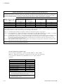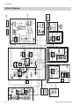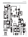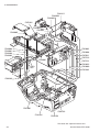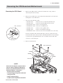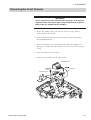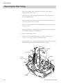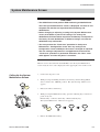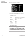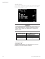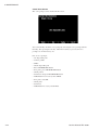
1
TEC- 5521B
TEC- 5521C
TEC- 5521E
TEC- 5521K
TEC- 5531B
TEC- 5531C
TEC- 5531E
TEC- 5531K
SERVICE MANUAL
DEFIBRILLATOR
TEC-5500
0634-002155C
Tradmark
The mark printed on the holter card and SD card adapter that are used in this instrument is a trademark. The company
name and model name are trademarks and registered trademarks of each company.
CONTENTS
Contents
GENERAL HANDLING PRECAUTIONS ......................................................................... i
WARRANTY POLICY .................................................................................................... ii
EMC RELATED CAUTION ............................................................................................ iii
Conventions Used in this Manual and Instrument ......................................................... v
Section 1
General .................................................................................. 1C.1
Introduction .......................................................................................................................... 1.1
Models and Functions ................................................................................................ 1.1
General Information on Servicing ......................................................................................... 1.2
Service Policy, Service Parts and Patient Safety Checks .................................................... 1.4
Service Policy ............................................................................................................ 1.4
Service Parts ............................................................................................................. 1.4
Patient Safety Checks ............................................................................................... 1.5
Maintenance Equipments and Tools ........................................................................... 1.5
Specifications ...................................................................................................................... 1.6
Defibrillator ....................................................................................................... 1.6
Noninvasive Pacing (TEC-5531 series only) .................................................... 1.8
External Paddle (ND-552VB/VC/VE/VK) .......................................................... 1.8
Battery ............................................................................................................. 1.8
Clock Accuracy ................................................................................................ 1.8
Environment ..................................................................................................... 1.8
Safety .............................................................................................................. 1.9
Monitor ............................................................................................................. 1.9
ECG Amplifier .................................................................................................. 1.9
Recorder ......................................................................................................... 1.10
Rhythm Recognition Detector ........................................................................ 1.10
Power Requirements ...................................................................................... 1.10
Dimensions and Weight .................................................................................. 1.10
Electromagnetic Compatibility ........................................................................ 1.11
Panel Description ............................................................................................................... 1.15
Front Panel ............................................................................................................... 1.15
Top Panel (TEC-5531 Series Only) ........................................................................... 1.16
External Paddles ...................................................................................................... 1.17
Left Side Panel ......................................................................................................... 1.17
Rear Panel ............................................................................................................... 1.18
Composition ....................................................................................................................... 1.19
Standard Components .............................................................................................. 1.19
Options ..................................................................................................................... 1.21
Board/Unit Location ............................................................................................................ 1.23
Block Diagram .................................................................................................................... 1.24
Section 2
Troubleshooting ................................................................... 2C.1
How to Troubleshoot ............................................................................................................. 2.1
Service Manual TEC-5500
C.1
CONTENTS
Error Code ............................................................................................................................ 2.2
Defibrillation ............................................................................................................... 2.3
Operation Panel .......................................................................................................... 2.4
Communication .......................................................................................................... 2.5
Data Error ................................................................................................................... 2.6
Pacing (TEC-5531 Series Only) .................................................................................. 2.6
Message ............................................................................................................................... 2.7
Troubleshooting .................................................................................................................... 2.9
General ....................................................................................................................... 2.9
Defibrillation ............................................................................................................. 2.10
Monitoring ................................................................................................................ 2.11
Recording ................................................................................................................. 2.13
Battery ..................................................................................................................... 2.13
Pacing (TEC-5531 Series Only) ................................................................................ 2.14
Section 3
Disassembly ......................................................................... 3C.1
Before You Begin .................................................................................................................. 3.1
Warnings, Cautions and Notes ................................................................................... 3.1
Required Tools ............................................................................................................ 3.2
Connection Diagram ............................................................................................................. 3.3
Removing the Lower Casing ................................................................................................. 3.5
Removing the Paddles ............................................................................................... 3.5
Removing the Battery Pack ....................................................................................... 3.5
Removing the Lower Casing ....................................................................................... 3.6
Removing the CPU Board and Mother board ........................................................................ 3.7
Removing the CPU Board .......................................................................................... 3.7
Removing the Mother Board ...................................................................................... 3.8
Removing the Front Chassis ................................................................................................ 3.9
Removing the Side Casing ................................................................................................. 3.10
Removing the Recorder Unit .................................................................................... 3.11
Removing the Biphasic HV Unit ......................................................................................... 3.12
Removing the HV Capacitor ............................................................................................... 3.14
Attaching the HV Capacitor ...................................................................................... 3.15
Removing the AC/DC Unit .................................................................................................. 3.16
Removing the Test Load Board ........................................................................................... 3.17
Removing the Pacer Board (TEC-5531 Series Only) .......................................................... 3.18
Removing the LCD Unit ...................................................................................................... 3.19
Removing the Key Board .................................................................................................... 3.20
Removing the Energy/Mode Select Control Knob ..................................................... 3.20
Removing the Speaker ....................................................................................................... 3.21
Removing the Paddle Lock Springs .................................................................................... 3.22
Removing the AC SOURCE Socket ................................................................................... 3.23
Section 4
Maintenance ......................................................................... 4C.1
General ................................................................................................................................. 4.1
Daily Checks .................................................................................................... 4.1
Monthly Checks ............................................................................................... 4.1
C.2
Service Manual TEC-5500
CONTENTS
System Maintenance Screen ............................................................................................... 4.3
Calling Up the System Maintenance Screen .............................................................. 4.3
About the Menu Items ................................................................................................ 4.4
System Maintenance Screen Flowchart ........................................................... 4.5
Default Settings ............................................................................................... 4.6
Flash Save Procedure ................................................................................................ 4.7
Configuration Screen .................................................................................................. 4.8
Adjust AD Screen ...................................................................................................... 4.9
Adjust ECG A/D Screen ................................................................................. 4.10
Adjust HV AD Screen .................................................................................... 4.12
Adjust Battery AD Screen .............................................................................. 4.15
Paddle Contact A/D Screen ........................................................................... 4.16
Check Hardware Screen ........................................................................................... 4.17
Check Key Screen ......................................................................................... 4.17
Check LED Screen ........................................................................................ 4.19
Check LCD Screen ........................................................................................ 4.19
Check Recorder Screen ................................................................................. 4.19
Check Time Constant Screen ........................................................................ 4.20
Check Buzzer Screen .................................................................................... 4.21
Check Memory Screen ................................................................................... 4.21
Check Voice Screen ....................................................................................... 4.22
Check ECG Frequency Screen ...................................................................... 4.23
A/D View Screen ...................................................................................................... 4.24
Operation Time Screen ............................................................................................. 4.24
Version Up Screen ................................................................................................... 4.25
Debug Mode Screen ................................................................................................. 4.25
Check String Screen ...................................................................................... 4.26
Memory Dump Screen ................................................................................... 4.26
Periodic Replacement Schedule ......................................................................................... 4.27
Maintenance Check Sheet ................................................................................................. 4.28
Section 5
Replaceable Parts List......................................................... 5C.1
Replaceable Parts List ......................................................................................................... 5.2
Service Manual TEC-5500
C.3
CONTENTS
This page is intentionally left blank.
C.4
Service Manual TEC-5500
GENERAL HANDLING PRECAUTIONS
This device is intended for use only by qualified medical personnel.
Use only Nihon Kohden approved products with this device. Use of non-approved products or in
a non-approved manner may affect the performance specifications of the device. This includes,
but is not limited to, batteries, recording paper, pens, extension cables, electrode leads, input
boxes and AC power.
Please read these precautions thoroughly before attempting to operate the instrument.
1. To safely and effectively use the instrument, its operation must be fully understood.
2. When installing or storing the instrument, take the following precautions:
(1) Avoid moisture or contact with water, extreme atmospheric pressure, excessive humidity and temperatures, poorly
ventilated areas, and dust, saline or sulphuric air.
(2) Place the instrument on an even, level floor. Avoid vibration and mechanical shock, even during transport.
(3) Avoid placing in an area where chemicals are stored or where there is danger of gas leakage.
(4) The power line source to be applied to the instrument must correspond in frequency and voltage to product
specifications, and have sufficient current capacity.
(5) Choose a room where a proper grounding facility is available.
3. Before Operation
(1) Check that the instrument is in perfect operating order.
(2) Check that the instrument is grounded properly.
(3) Check that all cords are connected properly.
(4) Pay extra attention when the instrument is in combination with other instruments to avoid misdiagnosis or other
problems.
(5) All circuitry used for direct patient connection must be doubly checked.
(6) Check that battery level is acceptable and battery condition is good when using battery-operated models.
4. During Operation
(1) Both the instrument and the patient must receive continual, careful attention.
(2) Turn power off or remove electrodes and/or transducers when necessary to assure the patient’s safety.
(3) Avoid direct contact between the instrument housing and the patient.
5. To Shutdown After Use
(1) Turn power off with all controls returned to their original positions.
(2) Remove the cords gently; do not use force to remove them.
(3) Clean the instrument together with all accessories for their next use.
6. The instrument must receive expert, professional attention for maintenance and repairs. When the instrument is
not functioning properly, it should be clearly marked to avoid operation while it is out of order.
7. The instrument must not be altered or modified in any way.
8. Maintenance and Inspection:
(1) The instrument and parts must undergo regular maintenance inspection at least every 6 months.
(2) If stored for extended periods without being used, make sure prior to operation that the instrument is in perfect
operating condition.
Service Manual TEC-5500
i
(3) Technical information such as parts list, descriptions, calibration instructions or other information is available for
qualified user technical personnel upon request from your Nihon Kohden distributor.
9. When the instrument is used with an electrosurgical instrument, pay careful attention to the application and/or
location of electrodes and/or transducers to avoid possible burn to the patient.
WARRANTY POLICY
Nihon Kohden Corporation (NKC) shall warrant its products against all defects in materials and workmanship for one year
from the date of delivery. However, consumable materials such as recording paper, ink, stylus and battery are excluded from
the warranty.
NKC or its authorized agents will repair or replace any products which prove to be defective during the warranty period,
provided these products are used as prescribed by the operating instructions given in the operator’s and service manuals.
No other party is authorized to make any warranty or assume liability for NKC’s products. NKC will not recognize any other
warranty, either implied or in writing. In addition, service, technical modification or any other product change performed by
someone other than NKC or its authorized agents without prior consent of NKC may be cause for voiding this warranty.
Defective products or parts must be returned to NKC or its authorized agents, along with an explanation of the failure.
Shipping costs must be pre-paid.
This warranty does not apply to products that have been modified, disassembled, reinstalled or repaired without Nihon
Kohden approval or which have been subjected to neglect or accident, damage due to accident, fire, lightning, vandalism,
water or other casualty, improper installation or application, or on which the original identification marks have been
removed.
In the USA and Canada other warranty policies may apply.
CAUTION
United States law restricts this device to sale by or on the order of a physician.
ii
Service Manual TEC-5500
EMC RELATED CAUTION
This equipment and/or system complies with IEC 60601-2 International Standard for electromagnetic
compatibility for medical electrical equipment and/or system. However, an electromagnetic
environment that exceeds the limits or levels stipulated in IEC 60601-1-2, can cause harmful
interference to the equipment and/or system or cause the equipment and/or system to fail to perform
its intended function or degrade its intended performance. Therefore, during the operation of the
equipment and/or system, if there is any undesired deviation from its intended operational
performance, you must avoid, identify and resolve the adverse electromagnetic effect before continuing
to use the equipment and/or system.
The following describes some common interference sources and remedial actions:
1. Strong electromagnetic interference from a nearby emitter source such as an authorized radio station
or cellular phone:
Install the equipment and/or system at another location. Keep the emitter source such as cellular
phone away from the equipment and/or system, or turn off the cellular phone.
2. Radio-frequency interference from other equipment through the AC power supply of the equipment
and/or system:
Identify the cause of this interference and if possible remove this interference source. If this is not
possible, use a different power supply.
3. Effect of direct or indirect electrostatic discharge:
Make sure all users and patients in contact with the equipment and/or system are free from direct or
indirect electrostatic energy before using it. A humid room can help lessen this problem.
4. Electromagnetic interference with any radio wave receiver such as radio or television:
If the equipment and/or system interferes with any radio wave receiver, locate the equipment and/or
system as far as possible from the radio wave receiver.
5. Interference of lightning
When lightning occurs near the location where the equipment and/or system is installed, excessive
voltage may be generated in the equipment and/or system. In such a case, disconnect the AC power
cord from the equipment and/or system and operate the equipment and/or system by battery power, or
use an uninterruptible power supply.
6. Use with other equipment
When the equipment and/or system is adjacent to or stacked with other equipment, the equipment and/
or system may affect the other equipment. Before use, check that the equipment and/or system
operates normally with the other equipment.
7. Use of unspecified accessory, transducer and/or cable
When an unspecified accessory, transducer and/or cable is connected to this equipment and/or
system, it may cause increased electromagnetic emission or decreased electromagnetic immunity. The
specified configuration of this equipment and/or system complies with the electromagnetic
requirements with the specified configuration. Only use this equipment and/or system with the
specified configuration.
Service Manual TEC-5500
iii
Caution - continued
8. Use of unspecified configuration
When the equipment and/or system is used with the unspecified system configuration different than
the configuration of EMC testing, it may cause increased electromagnetic emission or decreased
electromagnetic immunity. Only use this equipment and/or system with the specified configuration.
9. Measurement with excessive sensitivity
The equipment and/or system is designed to measure bioelectrical signals with a specified sensitivity.
If the equipment and/or system is used with excessive sensitivity, artifact may appear by
electromagnetic interference and this may cause mis-diagnosis. When unexpected artifact appears,
inspect the surrounding electromagnetic conditions and remove this artifact source.
If the above suggested remedial actions do not solve the problem, consult your Nihon Kohden distributor
or representative for additional suggestions.
For EMC compliance, refer to “Specification - Electromagnetic Compatibility” in the Reference section
The CE mark is a protected conformity mark of the European Community. The products herewith comply with the
requirements of the Medical Device Directive 93/42/EEC.
NOTE about Waste Electrical and Electronic Equipment (WEEE) directive 2002/96/EEC
For the member states of the European Union only:
The purpose of WEEE directive 2002/96/EEC is, as a first priority, the prevention of waste electrical and
electronic equipment (WEEE), and in addition, the reuse, recycling and other forms of recovery of such
wastes so as to reduce the disposal of waste.
Contact your Nihon Kohden representative for disposal at the end of its working life.
iv
Service Manual TEC-5500
Conventions Used in this Manual and Instrument
Dangers, Warnings, Cautions and Notes
Dangers, Warnings, cautions and notes are used in this manual to alert or signal the reader to specific information.
DANGER
A danger is used to alert the user to a hazardous situation which will cause death or serious injury.
WARNING
A warning alerts the user to the possible injury or death associated with the use or misuse of the
instrument.
CAUTION
A caution alerts the user to possible injury or problems with the instrument associated with its use or
misuse such as instrument malfunction, instrument failure, damage to the instrument, or damage to other
property.
NOTE
A note provides specific information, in the form of recommendations, prerequirements, alternative
methods or supplemental information.
Service Manual TEC-5500
v
This page is intentionally left blank.
vi
Service Manual TEC-5500
Section 1 General
Introduction ......................................................................................................................... 1.1
Models and Functions ............................................................................................... 1.1
General Information on Servicing ........................................................................................ 1.2
Service Policy, Service Parts and Patient Safety Checks ................................................... 1.4
Service Policy ........................................................................................................... 1.4
Service Parts ............................................................................................................ 1.4
Patient Safety Checks .............................................................................................. 1.5
Maintenance Equipments and Tools .......................................................................... 1.5
Specifications ..................................................................................................................... 1.6
Defibrillator ...................................................................................................... 1.6
Noninvasive Pacing (TEC-5531 series only) ................................................... 1.8
External Paddle (ND-552VB/VC/VE/VK) ......................................................... 1.8
Battery ............................................................................................................ 1.8
Clock Accuracy ............................................................................................... 1.8
Envionment ..................................................................................................... 1.8
Safety ............................................................................................................. 1.9
Monitor ............................................................................................................ 1.9
ECG Amplifter ................................................................................................. 1.9
Recorder ........................................................................................................ 1.10
Rhythm Recognition Detector ....................................................................... 1.10
Power Requirements ..................................................................................... 1.10
Dimensions and Weight ................................................................................. 1.10
Electromagnetic Compatibility ....................................................................... 1.11
Panel Description .............................................................................................................. 1.15
Front Panel .............................................................................................................. 1.15
Top Panel (TEC-5531 Series Only) .......................................................................... 1.16
External Paddles ..................................................................................................... 1.17
Left Side Panel ........................................................................................................ 1.17
Rear Panel .............................................................................................................. 1.18
Composition ...................................................................................................................... 1.19
Standard Components ............................................................................................. 1.19
Options .................................................................................................................... 1.21
Board/Unit Location ........................................................................................................... 1.23
Block Diagram ................................................................................................................... 1.24
Service Manual TEC-5500
1C.1
This page is intentionally left blank.
1C.2
Service Manual TEC-5500
1. GENERAL
Introduction
This service manual provides useful information to qualified service personnel to
understand, troubleshoot, service, maintain and repair this TEC-5500 series
defibrillator.
The information in the operator’s manual is primarily for the user. However, it is
important for service personnel to thoroughly read the operator’s manual and
service manual before starting to troubleshoot, service, maintain or repair this
defibrillator. This is because service personnel needs to understand the operation
of the defibrillator in order to effectively use the information in the service
manual.
Models and Functions
Functions
TEC-5521
TEC-5531
External paddles
Standard
Standard
Internal paddles
Option
Option
Disposable pads
Option
Option
Pediatric electrode assy 44 mm φ
Option
Option
3 lead ECG
Standard
Standard
AED function
Standard
Standard
Noninvasive pacing
Not available
Standard
SpO2 measurement
Option
Option
CO2 measurement
Option
Option
Standard
Standard
5 lead ECG
Option
Option
External ECG input
Option
Option
External ECG output
Option
Option
SD card slot
Standard
Standard
Sound recording
Standard
Standard
Defibrillation and
synchronized
cardioversion
Voice prompt
Service Manual TEC-5500
1.1
1. GENERAL
General Information on Servicing
Note the following information when servicing the defibrillator.
CAUTIONS
Safety
• There is the possibility that the outside surface of the defibrillator,
such as the operation keys, could be contaminated by contagious
germs, so disinfect and clean the defibrillator before servicing it.
When servicing the defibrillator, wear rubber gloves to protect yourself
from infection.
• There is the possibility that when the lithium battery is broken, a
solvent inside the lithium battery could flow out or a toxic substance
inside it could come out. If the solvent or toxic substance touches
your skin or gets into your eye or mouth, immediately wash it with a
lot of water and see a physician.
Liquid ingress
The defibrillator is not waterproof, so do not install the defibrillator
where water or liquid can get into or fall on the defibrillator. If liquid
accidentally gets into the defibrillator or the defibrillator accidentally
drops into liquid, disassemble the instrument, clean it with clean
water and dry it completely. After reassembling, verify that there is
nothing wrong with the patient safety checks and function/
performance checks. If there is something wrong with the
defibrillator, contact your Nihon Kohden representative for repair.
Environmental Safeguards
Depending on the local laws in your community, it may be illegal to
dispose of the lithium battery in the regular waste collection. Check
with your local officials for proper disposal procedures.
Disinfection and cleaning
To disinfect the outside surface of the defibrillator, wipe it with a nonabrasive cloth moistened with any of the disinfectants listed below.
Do not use any other disinfectants or ultraviolet rays to disinfect the
defibrillator.
- Chlorohexidine gluconate solution:
0.5%
- Benzethonium chloride solution:
0.2%
- Glutaraldehyde solution:
2.0%
- Benzalkonium chloride:
0.2%
- Hydrochloric alkyl diaminoethylglycine:
0.5%
1.2
Service Manual TEC-5500
1. GENERAL
Caution - continued
Transport
• Use the specified shipment container and packing material to
transport the defibrillator. If necessary, double pack the defibrillator.
Also, put the defibrillator into the shipment container after packing so
that the buffer material does not get into the inside of the defibrillator.
• When transporting a board or unit of the defibrillator, be sure to use a
conductive bag on. Never use an aluminum bag when transporting a
board or unit on which a lithium battery is mounted. Also, never use
a styrene foam or plastic bag which generates static electricity to wrap
the board or unit of the defibrillator.
Handling the defibrillator
• Because the outside surface of the defibrillator is made of resin, the
outside surface of the defibrillator is easily damaged. So when
handling the defibrillator, remove clutter from around the defibrillator
and be careful to not damage the defibrillator or get it dirty.
• Because most of the boards in the defibrillator are multilayer boards
with surface mounted electrical devices (SMD), when removing and
soldering the electrical devices, a special tool is required. To avoid
damaging other electrical components, do not remove and solder
SMD components yourself.
Measuring and Test Equipment
Maintain the accuracy of the measuring and test equipment by
checking and calibrating it according to the check and calibration
procedures.
Service Manual TEC-5500
1.3
1. GENERAL
Service Policy, Service Parts and Patient Safety Checks
Service Policy
Our technical service policy for this defibrillator is to replace the faulty unit, board
or part or damaged mechanical part with a new one. Do not perform electrical
device or component level repair of the multilayer board or unit. We do not support
component level repair outside the factory for the following reasons:
• Most of the boards are multilayer boards with surface mounted electrical
devices, so the mounting density of the board is too high.
• A special tool or high degree of repair skill is required to repair the multilayer
boards with surface mounted electrical devices.
Only disassemble the defibrillator or replace a board or unit in an environment
where the defibrillator is protected against static electricity.
As background knowledge for repair, pay special attention to the following:
• You can reduce the repair time by considering the problem before starting repair.
• You can clarify the source of most of the troubles using the information from the
troubleshooting tables. Refer to “Troubleshooting“ of this manual.
Service Parts
Refer to “Replaceable Parts List” of this manual for the service parts for technical
service that we provide.
NOTE
When ordering parts or accessories from your Nihon Kohden
representative, please quote the NK code number and part name
which is listed in this service manual, and the name or model of the
unit in which the required part is located. This will help us to
promptly attend to your needs. Always use parts and accessories
recommended or supplied by Nihon Kohden Corporation to assure
maximum performance from your defibrillator.
1.4
Service Manual TEC-5500
1. GENERAL
Patient Safety Checks
Periodic maintenance procedures and diagnostic check procedures are provided in
this manual to ensure that the defibrillator is operating in accordance with its
design and production specifications. To verify that the defibrillator is working in
a safe manner with regard to patient safety, patient safety checks should be
performed on the defibrillator before it is first installed, periodically after
installation, and after any repair is made on the defibrillator.
For patient safety checks, perform the following checks as described in the
IEC60601-1 “Medical electrical equipment - Part 1: General requirements for
safety”:
• Protective earth resistance check
• Earth leakage current check
• Enclosure leakage current check
• Patient leakage current check
• Withstanding voltage check
Maintenance Equipments
and Tools
Service Manual TEC-5500
Test equipment
When repairing or calibrating the defibrillator, the following test equipment is
required.
• Oscilloscope: 2 channels or more for input signal, 50 mV to 5 V input range, 1/
10 attenuating probe and 100 MHz or more frequency response characteristic
must be provided.
• Power supply
• Oscillator: standard type
• Digital voltmeter: standard type (An oscilloscope can be used instead of the
digital voltmeter.)
1.5
1. GENERAL
Specifications
Defibrillator
Output energy (across 50 Ω)
Energy accuracy
2, 3, 5, 7, 10, 15, 20, 30, 50, 70, 100, 150, 200 and 270 J
2 J: ±0.5 J
3 J: ±1 J
5 to 15 J: ±2 J
20 to 270 J: ±10%
Biphasic, truncated exponential constant power (across 50 Ω)
Output waveform
Charging time
Manual mode
When powered by AC 100 V to 240 V:
to 270 J, maximum 5 s
to 200 J, maximum 3 s
to 270 J, maximum 5 s
to 270 J, maximum 5 s
to 200 J, maximum 3 s
When powered by 90% of the rated mains voltage:
When powered by a fully charged new battery at 20°C ambient temperature:
After 15 discharges at 270 J with a fully charged new battery at 20°C
ambient temperature:
to 270 J, maximum 5 s
When powered by 90% of the rated mains voltage or after 15 discharges
at 270 J with a fully charged new battery at 20oC ambient temperature:
Power on to 270 J, maximum 31 s
AED mode
When powered by 90% of the rated mains voltage or after 15 discharges
at 270 J with a fully charged new battery at 20oC ambient temperature:
Power on to 270 J:
typical 17 s, maximum 31 s
Standby mode to 270 J:
typical 15 s, maximum 29 s
Charging display
Displays the charged energy value on the screen
Synchronized discharge
Available
From the peak of R wave to the peak of discharge: within 60 ms
Maximum continuous charge/discharge cycles at 270 J
20 cycles: 3 cycles per minute with 1 minute cool down period after every 1 minute charge/
discharge period
15 cycles: 3 cycles per minute with no cool down period
Maximum skin-disposable pad contact impedance for energy charging:
280 Ω
Load resistance
(Ω)
25
50
75
100
125
150
175
First phase
Ipk1 (A)
D1 (ms)
67.3
41.1
29.5
22.9
18.8
15.9
13.8
3.85
6.35
8.86
11.4
13.9
16.4
18.9
Second phase
Ipk2 (A)
D2 (ms)
15.5
12.7
11.0
9.81
8.96
8.29
7.76
3.62
3.62
3.62
3.62
3.62
3.62
3.62
Delivered energy : 270 J
1.6
Service Manual TEC-5500
1. GENERAL
60
60
50
40
current [A]
current [A]
25
40
20
20
0
0
-20
-20
0
2
4
6
8
10
12
14
16
18
20
22
24
0
2
4
6
8
10
time [ms]
16
18
20
22
24
14
16
18
20
22
24
16
18
20
22
24
30
75
100
40
20
current [A]
current [A]
14
time [ms]
60
20
0
10
0
-20
-10
0
2
4
6
8
10
12
14
16
18
20
22
24
0
2
4
6
8
10
time [ms]
12
time [ms]
30
30
125
150
20
20
current [A]
current [A]
12
10
0
10
0
-10
-10
0
2
4
6
8
10
12
14
16
18
20
22
24
time [ms]
0
2
4
6
8
10
12
14
time [ms]
30
175
current [A]
20
10
0
-10
0
2
4
6
8
10
12
14
16
18
20
22
24
time [ms]
Service Manual TEC-5500
1.7
1. GENERAL
Noninvasive Pacing (TEC-5531 series only)
Pacing rate
40 to 180 pulse/min in 10 pulse/min steps
Output current
8 to 200 mA in 1, 2, 5 or 10 mA steps (Set on the System Setup screen)
Pacing modes
Fixed and Demand
Maximum load resistance
Outputs 200 mA across 250 Ω, 120 mA across 500 Ω
External Paddle (ND-552VB/VC/VE/VK)
Paddle electrode size
For adults: 70 ±3 × 10⁶ ±3 (mm2)
For children: 45 ±3 × 53 ±3 (mm2)
Paddle cord length
2.0 m or more (when it is pulled by 18 N force)
Battery
Type
Ni-MH battery
Capacity
Nominal voltage: 12 V
Rated capacity: 2800 mAh
With fully charged new battery at 20°C ambient temperature
• Minimum 70 discharges at 270 J
• Minimum 150 minutes continuous monitoring
• Minimum 90 minutes fixed mode pacing (180 pulse/min, 200 mA)
With the fully charged new battery at 0°C, the defibrillator can perform:
• Minimum 50 discharges at 270 J
Clock Accuracy
At surrounding temeprature 25°C (77°F):
±3 min/month
At storage temperatures -20 to 70°C (-4 to 158°F): ±5 min/month
Environment
Operating temperature
Operating humidity
Operating atmospheric pressure
Storage temperature
Storage humidity
Storage atmospheric pressure
1.8
0 to 45°C (32 to 113°F)
30 to 95% (relative humidity, non-condensing)
70 to 106 kPa
(Recording paper may jam, if it is wet.)
-20 to 70°C (-4 to 158°F)
10 to 95% (relative humidity, non-condensing)
50 to 106 kPa
Service Manual TEC-5500
1. GENERAL
Safety
Safety standard
IEC 60601-1: 1988
IEC 60601-1 Amendment 1: 1991
IEC 60601-1 Amendment 2: 1995
IEC 60601-1-2: 2001
IEC 60601-2-4: 2002
According to the type of protection against electrical shock
Battery power:
INTERNALLY POWERED EQUIPMENT
AC power:
CLASS I EQUIPMENT
According to the degree of protection against electrical shock
DEFIBRILLATION-PROOF TYPE BF APPLIED PART
External paddles, disposable pads, SpO2 adapter and CO2 sensor kit
DEFIBRILLATION-PROOF TYPE CF APPLIED PART
Internal paddles, ECG connection cable
According to the degree of protection against harmful ingress of water
IPX1
According to the degree of safety of application in the presence of a FLAMMABLE ANAESTHETIC MIXTURE
WITH AIR, OR WITH OXYGEN OR NITROUS OXIDE
EQUIPMENT not suitable for use in the presence of FLAMMABLE
ANAESTHETIC MIXTURE WITH AIR, OR WITH OXYGEN OR NITROUS OXIDE
Mode of operation
Continuous operation with intermittent load:
Operation at defibrillation mode
Continuous operation:
All operation except above mentioned
Monitor
Effective display area
Sweep length
Sweep speed
Sensitivity
Amplitude limit
ECG Amplifier
Input signal
Frequency response
Input impedance
CMRR
AC filter
Pacing pulse rejection
External ECG input sensitivity
Heart rate counting range
Service Manual TEC-5500
117.2 (W) × 88.4 (H) mm (5.7 inch)
97 mm
25 mm/s, 50 mm/s
10 mm/1 mV ±5% (sensitivity ×1)
40 mm
PADDLE, I, II, III, aVR, aVL, aVF, V, AUX
Through paddles:
0.5 to 20 Hz (-3 dB)
Through ECG connection cable: 0.05 to 150 Hz (-3 dB)
AUX:
0.05 to 150 Hz (-3 dB)
Through paddles:
≥ 100 kΩ
Through ECG connection cable: ≥ 5 MΩ (at 10 Hz 1 mV)
AUX:
≥ 100 kΩ ±10%
≥ 100 dB (against chassis ground) when AC filter is ON
Available (common with 50/60 Hz)
ON at ≥ -20 dB, OFF
ON, OFF
10 mm/V ±5% (sensitivity ×1)
Defibrillation or monitoring mode: 15 to 300 bpm
Pacing mode:
15 to 220 bpm
1.9
1. GENERAL
Recorder
Paper speed
Types of recording
Manual recording:
Automatic recording:
Real time/delayed ECG waveform recording: 50, 25 mm/s
real time/delayed waveform recording, report recording, event recording
record on charging after discharge, alarm recording, periodic recording
Rhythm Recognition Detector
We evaluated the rhythm recognition detector of the TEC-5500 series defibrillator using the official
electrocardiogram database provided by AHA (American Heart Association) and MIT (Massachusetts Institute of
Technology) and an electrocardiogram database of over 3000 electrocardiograms from hospitals in Japan. According
to our own evaluation, the rhythm recognition detector of the TEC-5500 series defibrillator meets the equivalent of
AAMI standards ANSI/AAMI DF-39-1993 3.3.18.
Shockable Rhythm VF
Sensitivity: ≥ 90%
Shockable Rhythm VT
Sensitivity: ≥ 75%
All other Non-Shockable Rhythm Sensitivity: ≥ 95%
Power Requirements
•AC
Line voltage
Line frequency
Power input
•DC (Battery)
Power voltage
Power consumption
Charging time
100 to 240 V
50/60 Hz (automatic switching)
Intermittent load: 450 VA or less
Continuous load: 200 VA or less
12 V
Intermittent load: 18 A or less
Continuous load: 4.2 A or less
3 hours or less (with AC, with the power OFF)
Dimensions and Weight
Dimensions
290 (W) × 172 (H) × 355 (D) mm
Weight
TEC-5521 series defibrillator
6.1 kg (External paddles use, AC unit without battery)
5.3 kg (Pad adaptor use, AC unit without battery)
TEC-5531 series defibrillator
6.3 kg (External paddles use, AC unit without battery)
5.5 kg (Pad adaptor use, AC unit without battery)
1.10
Service Manual TEC-5500
1. GENERAL
Electromagnetic Compatibility
Standard
IEC 60601-1-2: 2001
Medical electrical equipment - Part 1-2: General requirements for safety - Collateral standard: Electromagnetic
compatibility - Requirements and tests
IEC 60601-2-4: 2002
Medical electrical equipment - Part 2-4: Particular requirement for the safety of cardiac defibrillators
Electromagnetic Emissions/Immunity Compliance Level and Guidance
Guidance and manufacturer’s declaration – electromagnetic emissions
The TEC-5500 series is intended for use in the electromagnetic environment specified below. The customer or the
user of the TEC-5500 series should assure that it is used in such an environment.
Emissions test
Compliance
Electromagnetic environment – guidance
The TEC-5500 series uses RF energy only for its internal
RF emissions
function. Therefore, its RF emissions are very low and are not
Group 1
CISPR 11
likely to cause any interference in nearby electronic
equipment.
RF emissions
Class B
CISPR 11
The TEC-5500 series is suitable for use in all establishments,
Harmonic emissions
including domestic establishments and those directly
Class A
IEC 61000-3-2
connected to the public low-voltage power supply network
Voltage fluctuations/
that supplies buildings used for domestic purposes.
Complies
flicker emissions
IEC 61000-3-3
Guidance and manufacturer’s declaration – electromagnetic immunity
The TEC-5500 series is intended for use in the electromagnetic environment specified below. The customer or the user of
the TEC-5500 series should assure that it is used in such an environment.
Immunity test
IEC 60601
Compliance level
Electromagnetic environment –
test level
guidance
Electrostatic
±6 kV contact
±6 kV contact
Floors should be wood, concrete or ceramic
discharge (ESD)
±8 kV air
±8 kV air
tile. If floors are covered with synthetic
IEC 61000-4-2
material, the relative humidity should be at
least 30%.
Electrical fast
±2 kV for power supply
±2 kV for power supply
Mains power quality should be that of a
transient/burst
lines
lines
typical commercial or hospital environment.
IEC 61000-4-4
Surge
±1 kV differential mode
±1 kV differential mode
Mains power quality should be that of a
IEC 61000-4-5
±2 kV common mode
±2 kV common mode
typical commercial or hospital environment.
<5% Ut
Voltage dips, short <5% Ut
Mains power quality should be that of a
(>95% dip in Ut)
interruptions and (>95% dip in Ut)
typical commercial or hospital environment. If
for 0.5 cycles
voltage variations for 0.5 cycles
the user of the TEC-5500 series requires
on power supply
continued operation during power mains
40% Ut
40% Ut
input lines
interruptions, it is recommended that the
(60% dip in Ut) for 5 cycles (60% dip in Ut) for 5
IEC 61000-4-11
TEC-5500 series be powered from an
cycles
uninterruptible power supply or a battery.
70% Ut
70% Ut
(30% dip in Ut) for
(30% dip in Ut) for
25 cycles
25 cycles
<5% Ut
Voltage dips, short <5% Ut
Mains power quality should be that of a
(>95% dip in Ut) for 5
interruptions and (>95% dip in Ut) for 5
typical commercial or hospital environment. If
seconds
voltage variations seconds
the user of the TEC-5500 series requires
on power supply
continued operation during power mains
input lines
interruptions, it is recommended that the
IEC 61000-4-11
TEC-5500 series be powered from an
uninterruptible power supply or a battery.
3 A/m
Power frequency magnetic fields should be at
Power frequency 3 A/m
levels characteristic of a typical location in a
(50/60 Hz)
typical commercial or hospital environment.
magnetic field
IEC 61000-4-8
NOTE: Ut is the AC mains voltage prior to application of the test level.
Service Manual TEC-5500
1.11
1. GENERAL
Guidance and manufacturer's declaration - electromagnetic immunity (1/2)
The TEC-5500 series is intended for use in the electromagnetic environment specified below. The customer or the
user of the TEC-5500 series should assure that it is used in such an environment.
Immunity test
IEC 60601
test level
Compliance level
Electromagnetic environment guidance
Portable and mobile RF communications
equipment should be used no closer to any part of
the TEC-5500 series, including cables, than the
recommended separation distance calculated from
the equation applicable to the frequency of the
transmitter.
Conducted RF
IEC 61000-4-6
Requirement of
IEC-60601-2-4:
3 Vrms
150 kHz to 80 MHz
outside ISM bandsa
3 Vrms
Recommended separation distance
d = 1.2√P
where P is the maximum output power rating of
the transmitter in watts (W) according to the
transmitter manufacturer and d is the
recommended separation distance in meters (m). b
Field strengths from fixed RF transmitters, as
determined by an electromagnetic site survey, c
should be less than the compliance level in each
frequency range. d
Interference may occur in the vicinity of
equipment marked with the following symbol:
NOTE 1:
NOTE 2:
a:
b:
c:
d:
•
•
1.12
At 80 MHz and 800 MHz, the higher frequency range applies.
These guidelines may not apply in all situations. Electromagnetic propagation is affected by absorption and
reflection from structures, objects and people.
The ISM (industrial, scientific and medical) bands between 150 kHz and 80 MHz are 6.765 MHz to 6.795 MHz;
13.553 MHz to 13.567 MHz; 26.957 MHz to 27.283 MHz; and 40.66 MHz to 40.70 MHz.
The compliance levels in the ISM frequency bands between 150 kHz and 80 MHz and in the frequency range 80
MHz to 2.5 GHz are intended to decrease the likelihood that mobile/portable communications equipment could
cause interference if it is inadvertently brought into patient areas. For this reason, an additional factor of 10/3 is
used in calculating the recommended separation distance for transmitters in these frequency ranges.
Field strengths from fixed transmitters, such as base stations for radio (cellular/cordless) telephones and land
mobile radios, amateur radio, AM and FM radio broadcast and TV broadcast cannot be predicted theoretically with
accuracy. To assess the electromagnetic environment due to fixed RF transmitters, an electromagnetic site survey
should be considered. If the measured field strength in the location in which the TEC-5500 series is used exceeds
the applicable RF compliance level above, the TEC-5500 series should be observed to verify normal operation. If
abnormal performance is observed, additional measures may be necessary, such as re-orienting or relocating the
TEC-5500 series.
Over the frequency range 150 kHz to 80 MHz, field strengths should be less than 3 V/m.
The JL-951T3 SpO2 adapter complies with IEC 60601-2: 1993 and it complies with IEC 60601-2: 2001 requirement
except for the item “Conducted RF”.
RRD is the abbreviation of Rhythm Recognition Detector.
Service Manual TEC-5500
1. GENERAL
Guidance and manufacturer's declaration - electromagnetic immunity (2/2)
The TEC-5500 series is intended for use in the electromagnetic environment specified below. The customer or the
user of the TEC-5500 series should assure that it is used in such an environment.
IEC 60601
test level
Immunity test
Compliance level
Electromagnetic environment guidance
Portable and mobile RF communications
equipment should be used no closer to any part of
the TEC-5500 series , including cables, than the
recommended separation distance calculated from
the equation applicable to the frequency of the
transmitter.
Radiated RF
IEC 61000-4-3
Recommended separation distance
d = 1.2√P
80 to 800 MHz
d = 2.3√P
800 MHz to 2.5 GHz
Requirement of IEC60601-2-4:
Correct operation of
RRD:
10 V/m
80 MHz to 2.5 GHz
No inadvertent
energy delivery is
allowed:
20 V/m
80 MHz to 2.5 GHz
3 V/m
Additional requirement of IEC 60601-2-4
Correct operation of RRD:
d = 4.0√P
80 to 800 MHz
d = 7.7√P
800 MHz to 2.5 GHz
20 V/m
No inadvertent energy delivery is allowed:
d = 0.6√P
80 to 800 MHz
d = 1.2√P
800 MHz to 2.5 GHz
where P is the maximum output power rating of
the transmitter in watts (W) according to the
transmitter manufacturer and d is the
recommended separation distance in meters (m). b
Field strengths from fixed RF transmitters, as
determined by an electromagnetic site survey, c
should be less than the compliance level in each
frequency range. d
Interference may occur in the vicinity of
equipment marked with the following symbol:
NOTE 1:
NOTE 2:
a:
b:
c:
d:
At 80 MHz and 800 MHz, the higher frequency range applies.
These guidelines may not apply in all situations. Electromagnetic propagation is affected by absorption and
reflection from structures, objects and people.
The ISM (industrial, scientific and medical) bands between 150 kHz and 80 MHz are 6.765 MHz to 6.795 MHz;
13.553 MHz to 13.567 MHz; 26.957 MHz to 27.283 MHz; and 40.66 MHz to 40.70 MHz.
The compliance levels in the ISM frequency bands between 150 kHz and 80 MHz and in the frequency range 80
MHz to 2.5 GHz are intended to decrease the likelihood that mobile/portable communications equipment could
cause interference if it is inadvertently brought into patient areas. For this reason, an additional factor of 10/3 is
used in calculating the recommended separation distance for transmitters in these frequency ranges.
Field strengths from fixed transmitters, such as base stations for radio (cellular/cordless) telephones and land
mobile radios, amateur radio, AM and FM radio broadcast and TV broadcast cannot be predicted theoretically with
accuracy. To assess the electromagnetic environment due to fixed RF transmitters, an electromagnetic site survey
should be considered. If the measured field strength in the location in which the TEC-5500 series is used exceeds
the applicable RF compliance level above, the TEC-5500 series should be observed to verify normal operation. If
abnormal performance is observed, additional measures may be necessary, such as re-orienting or relocating the
TEC-5500 series.
Over the frequency range 150 kHz to 80 MHz, field strengths should be less than 3 V/m.
Service Manual TEC-5500
1.13
1. GENERAL
Recommended separation distances between
portable and mobile RF communications equipment and the TEC-5500 series
The TEC-5500 series is intended for use in an electromagnetic environment in which radiated RF disturbances are
controlled. The customer or the user of the TEC-5500 series can help prevent electromagnetic interference by maintaining
a minimum distance between portable and mobile RF communications equipment (transmitters) and the TEC-5500
series as recommended below, according to the maximum output power of the communications equipment.
Separation distance according to frequency of transmitter (m)
Rated maximum output 150 kHz to 80 MHz 150 kHz to 80 MHz 80 MHz to 800 MHz
800 MHz to 2.5 GHz
power of transmitter outside ISM bands in ISM bands
d = 4.0√P
d = 7.7√P
(W)
d = 1.2√P
d = 1.2√P
0.01
0.12
0.12
0.4
0.77
0,1
0.38
0.38
1.3
2.4
1
1.2
1.2
4.0
7.7
10
3.8
3.8
13
27
100
12
12
40
77
For transmitters rated at a maximum output power not listed above, the recommended separation distance d in meters (m) can
be determined using the equation applicable to the frequency of the transmitter, where P is the maximum output power
rating of the transmitter in watts (W) according to the transmitter manufacturer.
NOTE 1: At 80 MHz and 800 MHz, the separation distance for the higher frequency range applies.
NOTE 2: The ISM (industrial, scientific and medical) bands between 150 kHz and 80 MHz are 6.765 MHz to 6.795 MHz;
13.553 MHz to 13.567 MHz; 26.957 MHz to 27.283 MHz; and 40.66 MHz to 40.70 MHz.
NOTE 3: An additional factor of 10/3 is used in calculating the recommended separation distance for transmitters in the
ISM frequency bands between 150 kHz and 80 MHz and in the frequency range 80 MHz to 2.5 GHz to
decrease the likelihood that mobile/portable communications equipment could cause interference if it is
inadvertently brought into patient areas.
NOTE 4: These guidelines may not apply in all situations. Electromagnetic propagation is affected by absorption and
reflection from structures, objects and people.
The equations and values in the above table show the condition that the RRD (Rhythm Recognition Detector) regulated in IEC
60601-2-4: 2002 does not receive electromagnetic interference.
System Configuration at EMC testing
We tested that the defibrillator complies with IEC 60601-1-1: 2001 and IEC
60601-2-4: 2002 with the following configuration. If other cables and equipments
are used with the defibrillator, the defibrillator may not comply with these
standards.
Configuration at testing
Cable length (m)
Defibrillator, TEC-5521/5531 series
DSI interface unit, QI-552V
External paddles, ND-552V
0.406
Pad adapter, JC-765V**
3.50
ECG connection cable, BC-763V
3.30
CO2 sensor kit, TG-901T3
2.99
SO2 adapter, JL-951T3*
2.50
Finger probe, TL-201T*
1.60
Battery pack, NKB-301V (YZ-024H9)
Holter card, QM-064D
*
When the SpO2 adapter and finger probe are connected to
the defibrillator, the defibrillator does not comply with the
item “Conducted RF” (IEC 60601-1-2: 2001).
** When the pad adapter is connected to the defibrillator, the
compliance level of the item “Radiated RF” (IEC
60601-2-4: 2002) is 3 V/m.
1.14
Service Manual TEC-5500
1. GENERAL
Panel Description
Front Panel
* When DSI interface unit
is connected
2
1
1
3
4
5
7
8
6
* When DSI/AUXOUT interface
unit is connected
9
10
11
Name
Service Manual TEC-5500
1
LCD display
2
Energy/Mode Select control
3
Microphone
4
SYNC button/lamp
5
CHARGE/AED button
6
DISCHARGE button
7
DISCHARGE lamp
8
ECG input connector
9
SpO2/CO2 connector
10
AUXOUT connector
11
Paddle connector
1.15
1. GENERAL
15
14
16
17
18
12
19
13
20
No.
Name
12
Record key
13
Event key
14
ECG lead key
15
ECG sensitivity key
16
Silence alarms key
17
Multi-function key
18
AC lamp
19
Battery charging lamp
20
Battery charge complete lamp
Top Panel (TEC-5531 Series Only)
1
3
2
4
6
5
Name
1.16
1
PACING RATE Up key
2
PACING RATE Down key
3
PACING OUTPUT Up key
4
PACING OUTPUT Down key
5
START/STOP key
6
PULSE lamp
Service Manual TEC-5500
1. GENERAL
External Paddles
4
4
1
2
3
Name
1
CONTACT lamp
2
CHARGE button
3
CHARGE lamp
4
DISCHARGE buttons
Left Side Panel
2
1
4
3
Name
Service Manual TEC-5500
1
Recording paper exit
2
Door release lever
3
SD card slot
4
Battery pack holder
1.17
1. GENERAL
Rear Panel
1
2
Name
1.18
1
AC SOURCE socket
2
Optional unit connector
Service Manual TEC-5500
1. GENERAL
Composition
Standard Components
TEC-5521B
TEC-5521C
TEC-5521E
TEC-5521K
HV-552V
Biphasic HV UNIT
UR-0311
HV CPU board
UR-0313
MOTHER board
UR-0314
CPU board
UR-0315
TEST LOAD board
UR-0316
KEY board
WS-551V
Recorder unit
RG-501X
Paper feeder
CD-0004
UR-0320
Service Manual TEC-5500
Motor assy
REC-EXT board
CY-0026
PRE assy
CY-0029
Main unit assy
ND-552VB
ND-552VC
ND-552VE
ND-552VK
External paddle for B version
External paddle for C version
External paddle for E version
External paddle for K version
ND-552X
External paddle assy
ND-611V
Adult plate assy
1.19
1. GENERAL
TEC-5531B
HV-553V
TEC-5531C
TEC-5531E
Biphasic HV Unit
UR-0311
HV CPU board
TEC-5531K
UR-0313
MOTHER board
UR-0314
CPU board
UR-0315
TEST LOAD board
UR-0316
KEY board
WS-551V
Recorder Unit
RG-501X
Paper feeder
CD-0004
UR-0320
1.20
Motor assy
REC-EXT board
UR-0304
Pacer board
CY-0026
PRE assy
CY-0029
Main unit assy
ND-552VB
ND-552VC
ND-552VE
ND-552VK
External paddle for B version
External paddle for C version
External paddle for E version
External paddle for K version
ND-552X
Extarnal paddle assy
ND-611V
Adult plate assy
Service Manual TEC-5500
1. GENERAL
Options
Service Manual TEC-5500
JC-761V
External ECG cable
JC-762V
Connection cable
JC-763V
Connection cable
ND-612V
Pediatric electrode, 44 mm φ
ND-762V
Internal paddle electrode, 25 mm φ
ND-763V
Internal paddle electrode, 35 mm φ
ND-764V
Internal paddle electrode, 45 mm φ
ND-765V
Internal paddle electrode, 55 mm φ
ND-766V
Internal paddle electrode, 65 mm φ
ND-767V
Internal paddle electrode, 75 mm φ
BC-765V
ECG connection cable (IEC, 5 leads)
BC-765VA
ECG connection cable (AHA, 5 leads)
JC-755V
Pad adapter
JC-765V
Pad adapter
KD-028A
Cart
DI-001A
Cart tray assembly
YZ-024H9
Battery pack, NKB-301V
YZ-025H0
Paste holder kit
1.21
1. GENERAL
YZ-024H3
YZ-024H4
YZ-024H5
YZ-024H6
TEC Accessory set (100 V/IEC)
TEC Accessory set (200 V/IEC)
TEC Accessory set (100 V/AHA)
TEC Accessory set (200 V/AHA)
BC-763V
BC-763VA
QI-552V
DSI Interface unit
UR-0317
QI-553V
DSI Float board
DSI/AUXOUT Interface unit
UR-0318
1.22
ECG connection cable (IEC, 3 leads) for YZ-04H3/YZ-024H4
ECG connection cable (AHA, 3 leads) for YZ-04H5/YZ-024H6
AUX OUT board
Service Manual TEC-5500
1. GENERAL
Board/Unit Location
HV capacitor
AC/DC unit
Test load board
LCD unit
Recorder unit
Mother board
CPU board
Biphasic HV unit
KEY board
Pacer board (TEC-5531 series only)
DSI interface unit (option)
Service Manual TEC-5500
1.23
1. GENERAL
Block Diagram
1.24
Service Manual TEC-5500
Section 2 Troubleshooting
How to Troubleshoot ............................................................................................................ 2.1
Error Code ........................................................................................................................... 2.2
Defibrillation .............................................................................................................. 2.3
Operation Panel ......................................................................................................... 2.4
Communication ......................................................................................................... 2.5
Data Error .................................................................................................................. 2.6
Pacing (TEC-5531 Series Only) ................................................................................. 2.6
Message .............................................................................................................................. 2.7
Troubleshooting ................................................................................................................... 2.9
General ...................................................................................................................... 2.9
Defibrillation ............................................................................................................ 2.10
Monitoring ............................................................................................................... 2.11
Recording ................................................................................................................ 2.13
Battery .................................................................................................................... 2.13
Pacing (TEC-5531 Series Only) ............................................................................... 2.14
Service Manual TEC-5500
2C.1
This page is intentionally left blank.
2C.2
Service Manual TEC-5500
2. TROUBLESHOOTING
How to Troubleshoot
Use this section to locate, identify and solve a problem in the defibrillator or an
error message displayed on the screen. The troubleshooting tables in this section
are divided into general problems and displayed error messages.
1. Determine which troubleshooting table to use. Also refer to “Messages and
Troubleshooting” in Section 10 of the Operator’s manual.
2. In the “Error Code”, “Message” or “Problem” column, find the trouble item
that matches the problem or error message.
3. Do the action recommended in the “Action” column. (Do the first action
recommended in the “Action” column).
4. If the problem or error message is not solved, do the next action recommended
in the “Action” column. (If this does not solve the problem, do the next
recommended sections.)
5. If none of the actions solve the problem, contact your Nihon Kohden
distributor or representative.
NOTE
Before contacting your NK distributor or representative for technical
support, please complete a copy of the Maintenance Check Sheet
(the original copy is provided at the end of the Section 4
“Maintenance”), and if possible, provide additional detailed
information on the problem. Send the complete copy of the
Maintenance Check Sheet to your NK distributor or representative.
This will allow your NK distributor or representative to provide you
with the best support.
Service Manual TEC-5500
2.1
2. TROUBLESHOOTING
Error Code
The defibrillator displays an error code if it detects an error when the power is
turned on and during operation.
NOTE
• For problems that are not reproducible, call up the System Setup
screen and print the REPORT HISTORY. Refer to the Operator's
Manual for the detail of this procedure. The error code will be lost
when the power is turned off.
• Always check all the cable connections in the defibrillator before
performing the action recommended in the troubleshooting tables in
this section. This is because a loose cable connection can cause the
defibrillator to display the error code.
An error code is displayed.
ERROR AXXX
ERROR CXXX
ERROR DXXX
ERROR KXXX
ERROR PXXX
Turn off the instrument, then turn on the instrument and do the same operation.
Is the error code
displayed?
Yes
No
Yes
Is the error code
displayed?
Refer to error code
description for detail.
2.2
No
The error code is saved
in the "Report History"?
Error AXXX, CXXX, DXXX and
KXXX:
Perform charge/discharge test.
Error PXXX
Perform pacing test.
No
Instrument is normal.
But find the cause of the error code.
Yes
Service Manual TEC-5500
2. TROUBLESHOOTING
Defibrillation
Error Code
Meaning
A501
During standby mode, the HV capacitor
Possible Cause
Faulty biphasic HV unit.
has more than 1 J energy more than one
Action
Discharge HV capacitor and
replace the biphasic HV unit.
continuous second.
A512
When charging is started, the HV
Faulty biphasic HV unit.
Replace the biphasic HV unit.
capacitor energy did not reach 1 J
Faulty HV capacitor.
Replace the HV capacitor
Faulty biphasic HV unit.
Replace the biphasic HV unit.
time.
Faulty HV capacitor.
Replace the HV capacitor
After charging, the capacitor energy
Faulty biphasic HV unit.
Replace the biphasic HV unit.
falls the specified value for each
Faulty HV capacitor.
Replace the HV capacitor
Faulty biphasic HV unit.
Replace the biphasic HV unit.
Faulty biphasic HV unit.
Replace the biphasic HV unit.
Internal discharge takes more than 20
Faulty biphasic HV unit.
Replace the biphasic HV unit.
seconds to complete.
Faulty CPU board.
Replace the CPU board.
HV capacitor's voltage did not reach its
Faulty biphasic HV unit.
Replace the biphasic HV unit.
The voltage of the HV capacitor
Faulty biphasic HV unit.
Replace the biphasic HV unit.
exceeds its specified voltage.
Faulty CPU board.
Replace the CPU board.
When the disposable pad is used,
Faulty biphasic HV unit.
Replace the biphasic HV unit.
12.5% or more of the charged energy
Faulty CPU board.
Replace the CPU board.
When discharging, the second phase
Faulty biphasic HV unit.
Replace the biphasic HV unit.
pulse is not output.
Faulty CPU board.
Replace the CPU board.
within 2 seconds.
A513
The energy is not reached to the
selected energy within the specified
A524
energy.
A527
After charging, the capacitor energy is
about 15% above the selected energy.
A529
After charging, the actual charged
energy is different from the selected
energy.
A556
A566
target value 20 seconds after adjusted
internal discharge.
A585
A587
remains in the HV capacitor 2 seconds
after external discharge.
A597
Service Manual TEC-5500
2.3
2. TROUBLESHOOTING
Operation Panel
NOTE
• When the power is on, the following key switch is pressed and held for more than 10
seconds, the error code of each key is displayed.
• If the key was not pressed and held, check each key function with the System
Maintenance screen. Refer to Section 4 “System Maintenance Screen - Check Hardware
Screen - Check Key Screen”.
Error Code
K501
The ECG lead key error is detected.
K502
The ECG sensitivity key error is
K503
K504
K505
K506
K507
K508
K509
K511
K512
K513
K516
K517
K518
K519
K520
2.4
Meaning
Possible Cause
Action
Faulty key board.
Replace the key board.
Faulty CPU board.
Replace the CPU board.
Faulty key board.
Replace the key board.
detected.
Faulty CPU board.
Replace the CPU board.
The ECG silence alarm key error is
Faulty key board.
Replace the key board.
detected.
Faulty CPU board.
Replace the CPU board.
The multi-function key error is detected.
Faulty key board.
Replace the key board.
Faulty CPU board.
Replace the CPU board.
Faulty key board.
Replace the key board.
Faulty CPU board.
Replace the CPU board.
Faulty key board.
Replace the key board.
Faulty CPU board.
Replace the CPU board.
The SYNC button error (front panel) is
Faulty key board.
Replace the key board.
detected.
Faulty CPU board.
Replace the CPU board.
The CHARGE button error (front panel)
Faulty key board.
Replace the key board.
is detected.
Faulty CPU board.
Replace the CPU board.
The DISCHARGE button error (front
Faulty key board.
Replace the key board.
panel) is detected.
Faulty CPU board.
Replace the CPU board.
The CHARGE button error (apex
Faulty external paddles.
Replace the external paddles.
external paddle) is detected.
Faulty CPU board.
Replace the CPU board.
The DISCHARGE button error (apex
Faulty external paddles.
Replace the external paddles.
external paddle) is detected.
Faulty CPU board.
Replace the CPU board.
The DISCHARGE button error
Faulty external paddles.
Replace the external paddles.
(sternum external paddle) is detected.
Faulty CPU board.
Replace the CPU board.
The PACING START/STOP key error
Faulty pacer board.
Replace the pacer board.
is detected.
Faulty CPU board.
Replace the CPU board.
PACING RATE Up key error
Faulty pacer board.
Replace the pacer board.
Faulty CPU board.
Replace the CPU board.
Faulty pacer board.
Replace the pacer board.
Faulty CPU board.
Replace the CPU board.
Faulty pacer board.
Replace the pacer board.
Faulty CPU board.
Replace the CPU board.
Faulty pacer board.
Replace the pacer board.
Faulty CPU board.
Replace the CPU board.
The record key error is detected.
The event key error is detected.
PACING RATE Down key error
PACING CURRENT Up key error
PACING CURRENT Down key error
Service Manual TEC-5500
2. TROUBLESHOOTING
Communication
Error Code
C501
C502
C505
Meaning
Possible Cause
Action
When the CO2 sensor kit is connected,
Faulty CO2 sensor kit.
Replace the CO2 sensor kit.
CO2 data is not received.
Faulty DSI Float board.
Replace the DSI Float board.
Faulty AUX OUT board.
Replace the AUX OUT board.
Faulty CPU board.
Replace the CPU board.
When the SpO2 adapter is connected,
Faulty SpO2 adapter.
Replace the SpO2 adapter.
SpO2 data is not received.
Faulty DSI Float board.
Replace the DSI Float board.
Faulty AUX OUT board.
Replace the AUX OUT board.
Faulty CPU board.
Replace the CPU board.
The battery CPU does not transfer the
Faulty mother board.
Replace the mother board.
battery data to the main CPU for more
Faulty CPU board.
Replace the CPU board.
Faulty CPU board.
Replace the CPU board.
Faulty CPU board.
Replace the CPU board.
Faulty CPU board.
Replace the CPU board.
The DSI CPU does not update the data
Faulty DSI Float board.
Replace the DSI Float board.
in the DPRAM for one second.
Faulty AUX OUT board.
Replace the AUX OUT board.
Faulty CPU board.
Replace the CPU board.
The pacing CPU does not update the
Faulty pacer board.
Replace the pacer board
data in the DPRAM for one second.
Faulty CPU board.
Replace the CPU board.
The HV CPU does not update the data
Faulty biphasic HV unit.
Replace the biphasic HV unit.
in the DPRAM for one second.
Faulty CPU board.
Replace the CPU board.
than 10 seconds.
C507
When the power is turned on, the
communication error between the RTC
(real time clock) and main CPU is
detected for one second.
C511
The sub CPU does not update the data
in the DPRAM for one second.
C512
The voice CPU does not update the data
in the DPRAM for one second.
C513
C514
C515
Service Manual TEC-5500
2.5
2. TROUBLESHOOTING
Data Error
Error Code
D501
Meaning
Possible Cause
Data in the DRAM or flash memory is
Faulty DRAM or flash
not read out correctly (summation
memory.
Action
Replace the CPU board.
error).
D511
D512
When the power is turned on, settings in
After settings in the System
Perform the “Flash Save”
the System Maintenance screen do not
Maintenance screen are
procedure in the System
match the backup data in the flash
changed, the “Flash Save”
Maintenance screen.
memory.
procedure is not performed.
During power off sequence,
Delete the report data in the
power down occurs.
System Setup screen.
Faulty CPU board.
Replace the CPU board.
When the power is turned on, damaged
During power off sequence,
Delete the report data in the
waveform report data in the flash
power down occurs.
System Setup screen.
memory is detected.
Faulty CPU board.
Replace the CPU board.
Pacing (TEC-5531 Series Only)
Error Code
Meaning
P502
Pulse width of the pacing output pulse is
Faulty pacer board.
Replace the pacer board.
larger or smaller than the selected width.
Faulty CPU board.
Replace the CPU board.
Current intensity of the pacing output
Faulty pacer board.
Replace the pacer board.
pulse is larger than the selected value.
Faulty CPU board.
Replace the CPU board.
Current intensity of the pacing output
Faulty pacer board.
Replace the pacer board.
pulse is smaller than the selected value.
Faulty CPU board.
Replace the CPU board.
Pacing output that is not requested by the
Faulty pacer board.
Replace the pacer board.
CPU is detected.
Faulty CPU board.
Replace the CPU board.
Pacing output voltage exceeds the upper
Faulty pacer board.
Replace the pacer board.
limit.
Faulty CPU board.
Replace the CPU board.
Error was detected in the short-mode of
Faulty pacer board.
Replace the pacer board.
P503
P504
P505
P506
P511
Possible Cause
Action
the transistor.
2.6
Service Manual TEC-5500
2. TROUBLESHOOTING
Message
Message
Meaning
Possible Cause
Action
Battery charge
During battery test, the battery
Faulty battery pack.
Replace the battery pack.
timed out
was not fully charged 5 hours
Faulty mother board.
Replace the mother board.
after battery charging started.
Battery charging
During battery test
Faulty battery pack.
Replace the battery pack.
error
An error occurred in battery
Faulty mother board.
Replace the mother board.
charging
Battery discharge
During battery test
Faulty battery pack.
Replace the battery pack.
timed out
The voltage did not decrease to
Faulty mother board.
Replace the mother board.
the specified level 4 hours after
Faulty CPU board.
Replace the CPU board.
Faulty biphasic HV unit.
Replace the biphasic HV unit.
Faulty HV capacitor.
Replace the HV capacitor.
Faulty CO2 sensor kit.
Replace the CO2 sensor kit.
Faulty the DSI Float board or
Replace the DSI Float board or
AUX OUT board.
AUX OUT board.
battery discharging started.
Capacitor test fail
CO2 module not
Capacitor test failed.
CO2 module is faulty.
working
CO2 module
CO2 cable is disconnected from
CO2 cable is disconnected from
Press the Silence alarm key to
disconnected
the defibrillator.
the DSI Interface Unit or
turn off the message. If the
DSI/AUX OUT Interface Unit.
message still appears, the DSI
Faulty DSI Float board or AUX
Float board or AUX OUT board
OUT board.
is faulty. Replace the DSI Float
board or AUX OUT board.
ERROR AXXX
Faulty HV
Turn off the defibrillator, then turn
ERROR CXXX
Communication error
on and do the same operation. If the
ERROR DXXX
Faulty ROM/RAM
ERROR KXXX
Faulty keys
ERROR PXXX
Faulty pacing unit
FET error
The circuit to measure remaining
---
message still appears, refer to the
table for each error code.
Faulty mother board.
Replace the mother board.
Faulty biphasic HV unit or CPU
Turn off the defibrillator, then turn
board.
on and do the same operation. If the
battery charge is faulty.
High voltage
Faulty high voltage monitor circuit.
monitor error
message still appears, the biphasic
HV unit or CPU board is faulty.
Replace the biphasic HV unit or
CPU board.
Service Manual TEC-5500
2.7
2. TROUBLESHOOTING
Message
Overheating
Meaning
Possible Cause
Action
The high voltage charge circuit
The defibrillator discharged too
Turn off the defibrillator and leave
heats up.
frequently.
the defibrillator for 10 minutes,
then turn on.
Power abnormality
Input power voltage is too high.
Not specified battery is used.
Only use the NKB-301V battery.
Relay drive error
Faulty biphasic HV unit.
Faulty biphasic HV unit.
Replace the biphasic HV unit.
Faulty CPU board.
Replace the CPU board.
Faulty battery pack.
Replace the battery.
Faulty the SpO2 adapter.
Replace the SpO2 adapter.
Faulty the DSI Float board or
Replace the DSI Float board or
AUX OUT board.
AUX OUT board.
Replace battery
Battery test result is 0 to 49%.
The defibrillator judged that the
battery should be replaced with a
new one.
SpO2 module not
SpO2 module is faulty.
working
SpO2 module
SpO2 cable is disconnected from
SpO2 cable is disconnected from
Press the Silence alarm key to
disconnected
the defibrillator.
the DSI interface unit or
turn off the message. If the
DSI/AUX OUT interface unit.
message still appears, the DSI
Faulty DSI Float board or AUX
Float board or AUX OUT board
OUT board.
is faulty. Replace the DSI Float
board or AUX OUT board.
2.8
Service Manual TEC-5500
2. TROUBLESHOOTING
Troubleshooting
General
Problem
The defibrillator heats up.
No operation when the defibrillator is
Possible Cause
Action
The defibrillator is used for many
There is no abnormality in the
hours.
defibrillator. Turn off the defibrillator
and disconnect the power cord.
The power cord is disconnected.
Firmly connect the power cord to the
turned on.
AC outlet and the defibrillator.
The battery is not installed.
Install the specified battery.
Faulty battery
Replace the battery with a new one
(NKB-301V).
Remaining battery charge is low.
Charge the battery.
Faulty key board.
Replace the key board.
Faulty mother board.
Replace the mother board.
Faulty AC/DC unit.
Replace the AC/DC unit.
Screen is dim. Waveform and
Faulty LCD inverter board.
Replace the LCD inverter board.
characters are not seen.
Faulty LCD unit.
Replace the LCD unit.
Faulty mother board.
Replace the mother board.
Faulty CPU board.
Replace the CPU board.
The backup battery is almost
Replace the CPU board. (Under normal
discharged.
use condition, the backup battery
lifetime is about 6 years.)
On the Setup screen, the report data
Deleted data cannot be recovered.
The printed data is JAN/01/80.
The report data are not saved.
were deleted.
All settings set in the Setup screen and
System Setup screen return to the
During power off sequence, power
Do not disconnect the AC power cord
down occurs.
or do not remove the battery while the
"Shutdown" message is displayed.
Faulty CPU board.
Replace the CPU board.
During power off sequence, power
Do not disconnect the AC power cord
down occurs.
or do not remove the battery while the
"Shutdown" message is displayed.
Faulty CPU board.
Replace the CPU board.
default settings.
Service Manual TEC-5500
2.9
2. TROUBLESHOOTING
Problem
When the battery is installed, the
Possible Cause
Power voltage changed.
Action
Check that the AC power cord is
defibrillator suddenly changes to
connected to the defibrillator. If the
battery operation.
trouble is not solved, the AC/DC unit or
AC power cord faulty. Replace the
AC/DC unit or AC power cord.
When the battery is not installed, the
defibrillator power suddenly drops.
The date and time printed on the
---
recording paper is incorrect.
Set the date and time on the Setup
screen. Refer to Section 3 of the
operator's manual
The backup battery for the clock is
Replace the backup battery.
discharged.
Faulty CPU board.
Replace the CPU board.
Defibrillation
Problem
Possible Cause
Action
The defibrillator self-discharges the
In battery operation, the battery is
Operate the defibrillator on AC power
energy during charging.
almost discharged.
and recharge the battery.
The battery
is automatically charged when the
defibrillator is connected to AC power.
Faulty biphasic HV unit.
When an error code appears on the
screen, refer to the Defibrillation table
Cannot switch to synchronized mode.
“0 J” is printed on the defibrillation
report recording.
2.10
(Error code appears on the screen.)
in the Error Code section.
Appropriate lead is not selected.
Change to the appropriate lead.
You tried to perform synchronized
cardioversion with the PADDLE lead
but synchronized cardioversion with
the PADDLE lead is set to OFF on
the Paddle Setup screen.
On the Paddle Setup screen, set the
“sync by paddle lead” to ON.
Faulty key board.
Replace the key board.
Faulty CPU board.
Replace the CPU board.
TTR is 15 Ω or less
Check that the paddles do not touch
each other.
TTR is 255 Ω or more.
Press the paddles on the patient
firmly.
Service Manual TEC-5500
2. TROUBLESHOOTING
Monitoring
ECG
Problem
Possible Cause
Action
Dotted lines appear instead of the ECG
An ECG electrode is detached.
Remove the cause of the trouble. If the
waveforms.
An electrode lead is disconnected from
trouble is not solved, the mother board
is fault. Replace the mother board.
the electrode.
The ECG connection cable is
disconnected from the defibrillator.
An electrode lead is faulty.
Faulty mother board.
No sync sound
Faulty CPU board.
Replace the CPU board.
No alarm is generated
The SILENCE ALARMS key is
Press the SILENCE ALARMS key
pressed.
again.
On the Setup screen, alarm is set to
On the Setup screen, set the
OFF.
upper/lower limit of each vital alarm.
Faulty CPU board.
Replace the CPU board.
Faulty speaker or speaker cable.
Replace the speaker
Faulty key board.
Replace the key board.
Faulty CPU board.
Replace the CPU board.
Possible Cause
The SpO2 adapter cable is disconnected
from the SpO2/CO2 connector.
Action
Connect the SpO2 adapter to the
SpO2/CO2 connector.
The SpO2 probe is disconnected from
the SpO2 adapter.
Firmly connect the probe to the SpO2
adapter.
Cable discontinuity in SpO2 adapter or
probe
Replace the SpO2 adapter or probe.
SpO2 probe attachment to the patient is
loose.
Firmly attach the probe to the patient.
Faulty SpO2 probe.
Replace the SpO2 probe.
Faulty SpO2 adapter.
Replace the SpO2 adapter.
Faulty DSI Float board.
Replace the DSI Float board.
Faulty AUX OUT board.
Replace the AUX OUT board.
Probe was disinfected in a way other
than the specified way.
Replace the probe with a new one.
Use the specified disinfecting method.
SpO2 probe is repeatedly used.
Replace the probe with a new one when
its lifetime is over.
No sound
SpO2
Problem
SpO2 value is not displayed on the
screen.
Dotted lines appear instead of the pulse
waveforms.
Deformed or damaged SpO2 probe
Service Manual TEC-5500
2.11
2. TROUBLESHOOTING
CO2
Problem
The measured value is not displayed on
the screen.
The red LED on the CO2 adapter
blinks.
2.12
Possible Cause
The CO2 sensor kit cable is
disconnected from the SpO2/CO2
connector.
Action
Connect the CO2 sensor kit cable to the
SpO2/ CO2 connector.
CO2 gas is in the inspiration.
With the CO2 sensor kit, measurements
are based on the assumption of no CO2
gas in the inspiration. Do not connect a
Jackson Rees respiration circuit or
Mapleson D respiration circuit to the
patient. Measurement cannot be done
correctly.
The airway adapter is dirty.
Replace the airway adapter with a new
one.
The measurement is preformed where
atmospheric pressure is low, such as at
high altitude.
Consider the atmospheric pressure
when making evaluations.
CO2 sensor or CO2 adapter is faulty.
Replace the CO2 sensor or CO2 adapter
with a new one.
The respiration has not been detected
for longer than 20 s.
The red LED blinks when the
respiration has not been detected for
longer than 20 s regardless of the alarm
setting on the defibrillator.
Service Manual TEC-5500
2. TROUBLESHOOTING
Recording
Problem
Printing is blurred. Dots are missing.
Possible Cause
The specified recording paper is not
Action
Use the specified recording paper.
used.
The thermal head is dirty.
Clean the thermal head with the head
cleaning pen. If the trouble not solved,
the recorder unit is faulty. Replace the
recorder unit.
There is no printing.
The recording paper is not loaded.
Load new recording paper.
Recording unit door is not properly
closed.
Close the door until it clicks.
The recording paper is set with the
Set the recording paper correctly.
wrong side facing up.
The thermal head heats up.
Stop recording and cool the
defibrillator down in a cooler place.
Faulty key board.
Check the key function and recorder
with the System Maintenance screen. If
the recorder check is passed, the key
board is faulty. Replace the key board.
Faulty recorder.
Faulty CPU board.
Printing is thick.
The recording unit temperature is too
hot.
Check the recorder in the System
Maintenance screen.
Cool the defibrillator down in a cooler
place. If the trouble is not solved, the
recorder unit or CPU board is faulty.
Replace the recorder unit or CPU
board.
Paper feeding speed is unstable.
The specified paper is not used.
Use the specified recording paper.
The recorder unit is not working.
Replace the recorder unit.
Faulty mother board.
Replace the mother board.
Battery
Problem
The battery charging lamp is blinking.
Possible Cause
Action
The defibrillator and battery are too
hot.
Bring the defibrillator to a cool place.
After starting battery charging, the
Faulty battery
Replace the battery with a new one.
charging stops. (neither battery
Charging circuit is not working.
Replace the mother board.
charging lamp nor battery charge
When the battery temperature
decreases, charging resumes.
complete lamp lights.)
Service Manual TEC-5500
2.13
2. TROUBLESHOOTING
Pacing (TEC-5531 Series Only)
Problem
Although the PULSE lamp is lit, pacing
Possible Cause
Action
Faulty pacer board.
Replace the pacer board.
Faulty CPU board.
Replace the CPU board.
Pacing current is set to 0 mA.
Set the appropriate pacing current with
pulse does not appear on the ECG.
Although the START/STOP lamp is lit,
pacing does not start.
the PACING OUTPUT control.
In DEMAND mode, selected pacing
Set the pacing rate appropriate for the
rate is slower than the patient heart rate.
patient heart rate. When the patient
heart rate is slower than the selected
pacing rate, pacing pulse is output
automatically.
2.14
Faulty pacer board.
Replace the pacer board.
Faulty CPU board.
Replace the CPU board.
Service Manual TEC-5500
Section 3 Disassembly
Before You Begin ................................................................................................................. 3.1
Warnings, Cautions and Notes .................................................................................. 3.1
Required Tools ........................................................................................................... 3.2
Connection Diagram ............................................................................................................ 3.3
Removing the Lower Casing ................................................................................................ 3.5
Removing the Paddles .............................................................................................. 3.5
Removing the Battery Pack ...................................................................................... 3.5
Removing the Lower Casing ...................................................................................... 3.6
Removing the CPU Board and Mother board ....................................................................... 3.7
Removing the CPU Board ......................................................................................... 3.7
Removing the Mother Board ..................................................................................... 3.8
Removing the Front Chassis ............................................................................................... 3.9
Removing the Side Casing ................................................................................................ 3.10
Removing the Recorder Unit ................................................................................... 3.11
Removing the Biphasic HV Unit ........................................................................................ 3.12
Removing the HV Capacitor .............................................................................................. 3.14
Attaching the HV Capacitor ..................................................................................... 3.15
Removing the AC/DC Unit ................................................................................................. 3.16
Removing the Test Load Board .......................................................................................... 3.17
Removing the Pacer Board (TEC-5531 Series Only) ......................................................... 3.18
Removing the LCD Unit ..................................................................................................... 3.19
Removing the Key Board ................................................................................................... 3.20
Removing the Energy/Mode Select Control Knob .................................................... 3.20
Removing the Speaker ...................................................................................................... 3.21
Removing the Paddle Lock Springs ................................................................................... 3.22
Removing the AC SOURCE Socket .................................................................................. 3.23
Service Manual TEC-5500
3C.1
This page is intentionally left blank.
3C.2
Service Manual TEC-5500
3. DISASSEMBLY
The procedures in this section explain how to remove, replace and install major
components in the defibrillator.
Before You Begin
Warnings, Cautions and
Notes
WARNING
• The HV capacitor can store lethal amounts of energy. Discharge this
•
•
capacitor before touching any high voltage component (HV capacitor,
biphasic HV unit, paddle socket or paddles).
Removal and replacement of any components in the defibrillator
should only be done by qualified service personnel.
To avoid the possibility of injury to yourself or damage to the
defibrillator, do not install or remove any component while the power
is on. When disassembling, make sure that the defibrillator is off, the
AC power cord is disconnected from the defibrillator and the battery
pack is removed from the defibrillator.
There are several high voltage units inside the defibrillator:
LCD backlight, high voltage capacitor, pacing DC/DC converter and
switching regulator.
CAUTIONS
• To avoid accidental discharge of static electricity which could damage
the components of the defibrillator, use a grounded wrist strap when
installing or removing any component of the defibrillator.
• Fuses on the main board and AC/DC unit cut off the power when an
abnormality occurs in the defibrillator. Eliminate the malfunction
before replacing the fuse. Use the correct fuse only.
• Use only parts recommended by Nihon Kohden to assure maximum
performance from your defibrillator.
Service Manual TEC-5500
3.1
3. DISASSEMBLY
NOTE
When the mother board, CPU board, biphasic HV unit, HV capacitor is
replaced with a new one, do the following adjustment. Refer to
“System Maintenance Screen - Adjust AD Screen” in Section 4.
Mother board:
- ECG sensitivity and offset
- Battery voltage setting
- Paddle contact impedance threshold
CPU board:
- ECG sensitivity and offset
- Charge energy, charge time, delivered energy and TTR
- Battery voltage setting
- Paddle contact impedance threshold
Biphasic HV unit:
- Charge energy, charge time, delivered energy and TTR
- Paddle contact impedance threshold
HV capacitor:
- Charge energy, charge time, delivered energy and TTR
Required Tools
3.2
•
•
•
•
•
•
•
Anti-static bench mat
Wrist ground strap
Phillips screwdriver (insulated type, for M3 and M4 screws)
Hex socket driver (for 3 mm spacer bolt and nut)
Allen wrench
Tweezers
Short bar
Service Manual TEC-5500
3. DISASSEMBLY
TEC-5531 series only
Connection Diagram
Service Manual TEC-5500
3.3
3. DISASSEMBLY
CNA411
CNA603
CNA002
CNP401
CNA602
CNA501
CNA605
CNA501
CNA604
CNA601
CNA304
CNA001
CNA302
CNP011
CNA004
CNP132
CNA901
CNP131
CNA022
CNA003
CNA201
CNA
501
CNA303
CNP301
CNA192
CNA191
CNA153
TEC-5531 with optional interface unit
3.4
Service Manual TEC-5500
3. DISASSEMBLY
Removing the Lower Casing
Removing the Paddles
1. Make sure that the power of the defibrillator is turned off.
2. Disconnect the AC power cord from the AC outlet and
defibrillator.
3. Remove the paddles. To remove the paddles, press and
hold the paddle release knob on the paddle connector and
pull the paddle connector toward you.
Paddle connector
CAUTION
When removing the paddle, do not pull anywhere
other than the paddle connector. Otherwise, the
paddle connector or paddle cable may be damaged.
Paddle release knob
4. If the SD card is inserted, remove it. To remove the SD
card, push it in, then pull it out.
Battery pack
SD card
Battery pack holder cover
Removing the Battery Pack
1. Turn the knob on the battery holder cover
counterclockwise and remove the battery pack holder
cover.
2. Disconnect the battery cable by holding the battery cable
connector and remove the battery from the defibrillator.
Service Manual TEC-5500
3.5
3. DISASSEMBLY
Removing the Lower
Casing
1. Remove the seven M4×10 binding head screws (BH) and two M3×8 binding
head screws.
2. Remove the lower casing from the upper casing.
If the optional DSI interface unit or DSI/AUXOUT interface unit is installed,
1) Remove the two M3×8 binding head screws.
2) Remove the interface unit and disconnect the CNA605 cable from the
defibrillator.
Interface unit
Lower casing
CNA605
3.6
Service Manual TEC-5500
3. DISASSEMBLY
Removing the CPU Board and Mother board
Removing the CPU Board
1. Remove the paddles, battery pack, SD card and lower casing. Refer to
“Removing the Lower Casing”.
2
Film connector
Film cable
Remove the six M3×8 pan screws with washers (PS) which secure the main
shield plate 1 to the CPU board.
3. Disconnect the following cables:
• CNA302 cable:
Connects to the recorder unit (thermal head)
• CNA304 cable:
Connects to the LCD INV (inverter) board
• CNA303 film cable: Connects to the LCD unit
• CNA601 film cable: Connects to the KEY board
• CNA602 cable:
Connects to the paddle socket
• CNA603 cable:
Connects to the biphasic HV unit
• CNA604 film cable: Connects to the Pacer board (TEC-5531 series only)
To remove the film cable from the film cable connector, gently release the
lock of the film cable connector with a small flat blade driver and your finger
as shown in the expanded illustration. Be careful because the film cable
connector is easily damaged.
4. Remove the CPU board.
Main shield plate 1
CNA604
CNA601
CNA303
CNA304
CNA602
CNA302
CNA603
CPU board
NOTE
When the CPU board is replaced with a
new one, do the following adjustment.
Refer to “System Maintenance Screen Adjust AD Screen” in Section 4.
- ECG sensitivity and offset
- Charge energy, charge time, delivered
energy and TTR
- Battery voltage setting
- Paddle contact impedance threshold
Service Manual TEC-5500
3.7
3. DISASSEMBLY
Removing the Mother
Board
When the CPU board is removed, you can remove the mother board.
1. Remove the main shield plate 2 and shield sheet.
2. Remove the six M3×8 spacer bolts which secure the mother board to the upper
casing.
3. Remove the two M3×8 binding head screws (BH) which secure the ECG
connector board to the front chassis
4. Disconnect the following cables:
• CNA501 cable: Connects to the battery pack, AC/DC unit and biphasic HV
unit
• CNP401 cable: Connects to the biphasic HV unit
• CNA901 cable: Connects to the recorder unit (REC-EXT board)
5. Remove the mother board from the upper casing.
Main shield plate 2
Shield sheet
CNP401
CNA901
Mother board
CNA501
ECG connector
board
CNJ101
NOTE
When the mother board is replaced with a new one, do the following
adjustment. Refer to “System Maintenance Screen - Adjust AD
Screen” in Section 4.
Mother board:
- ECG sensitivity and offset
- Battery voltage setting
- Paddle contact impedance threshold
3.8
Service Manual TEC-5500
3. DISASSEMBLY
Removing the Front Chassis
WARNING
The HV capacitor can store lethal amounts of energy. Discharge this
capacitor before touching any high voltage component (HV capacitor,
biphasic HV unit, paddle socket or paddles).
1. Remove the paddles, battery pack, SD card and lower casing. Refer to
“Removing the Lower Casing”.
2. Remove the CPU board and mother board. Refer to “Removing the CPU
Board and Mother Board”.
3. Remove the M3×8 pan screw with spring washer and washer (PSW), and
M3×6 pan screw with washer (PS) which secure the front chassis to the upper
casing.
4. Remove the cables from the cable tie.
5. Remove the front chassis from the upper casing.
Paddle socket
Cable tie
Front chassis
Service Manual TEC-5500
3.9
3. DISASSEMBLY
Removing the Side Casing
1. Remove the paddles, battery pack, SD card and lower casing. Refer to
“Removing the Lower Casing”.
2. Remove the CPU board and mother board. Refer to “Removing the CPU
Board and Mother Board”.
3. Remove the M3×8 pan screw with spring washer and washer (PSW) which
secures the cable tie to the spacer bolt.
4. Remove the M3×8 binding head screw (BH) which secures the side casing to
the upper casing.
5. Remove the M3×6 pan screw with washer (PS) which secures the terminal of
the CNA001 ground wire to the AC/DC unit.
6. Remove the M3×40 spacer bolt.
7. Remove the two M3×10 binding head screws which secure the battery
connector cover to the connector of the CNA501 cable.
8. Pull out the side casing. Note that the CNA303 film cable which connects the
LCD unit and CPU board runs through between the two hubs.
CNA501
Side casing
CNA001
Battery
connector cover
CNA303
3.10
Service Manual TEC-5500
3. DISASSEMBLY
Removing the Recorder
Unit
1. Remove the M3×8 pan screw with spring washer and washer (PSW) which
secures the recorder unit to the side casing.
2. Remove the recorder unit from the side casing.
Recorder unit
Service Manual TEC-5500
3.11
3. DISASSEMBLY
Removing the Biphasic HV Unit
WARNING
The HV capacitor can store lethal amounts of energy. Discharge this
capacitor before touching any high voltage component (HV capacitor,
biphasic HV unit, paddle socket or paddles).
1. Remove the paddles, battery pack, SD card and lower casing. Refer to
“Removing the Lower Casing”.
2. Remove the CPU board and mother board. Refer to “Removing the CPU
Board and Mother Board”.
3. Remove the front chassis. Refer to “Removing the Front Chassis”.
4. Remove the paddle socket.
1) Remove the M3×8 pan screw with spring washer and washer (PSW) which
secures the cable tie to the biphasic HV unit.
2) Remove the M3×6 pan screw with washer (PS) which secures the terminal
of the CNA002 ground wire to the AC/DC unit.
3) Disconnect the CNA411 cable from the biphasic HV unit.
Paddle socket
CNA411
CNA002
CNA022
CNA501
CNP011
CNP401
Biphasic HV unit
CNP131(Red)
3.12
CNP132
Service Manual TEC-5500
3. DISASSEMBLY
5. Disconnect the following cables:
• CNA501 cables: Connects to the battery pack, mother board and AC/DC
unit
• CNP011 cable: Connects to the Pacer board (TEC-5531 series only)
• CNA022 cable: Connects to the Pacer board (TEC-5531 series only)
6. Remove the two M3×6 pan screws with washers (PS) which secure the
terminals of CNP131 and CNP132 wires to the HV capacitor.
7. Pull out the biphasic HV unit.
NOTE
After replacing the biphasic HV unit, always check the following:
- Charge energy, charge time, delivered energy and TTR
- Paddle contact impedance threshold
Service Manual TEC-5500
3.13
3. DISASSEMBLY
Removing the HV Capacitor
WARNING
The HV capacitor can store lethal amounts of energy. Discharge this
capacitor before touching any high voltage component (HV capacitor,
biphasic HV unit, paddle socket or paddles).
1. Remove the paddles, battery pack, SD card and lower casing. Refer to
“Removing the Lower Casing”.
2. Remove the CPU board and mother board. Refer to “Removing the CPU
Board and Mother Board”.
3. Remove the side casing. Refer to “Removing the Side Casing”.
4. Remove the four M3×6 pan screws with washers (PS) which secure the
capacitor holders to the upper casing.
5. Remove the two M3×6 pan screws with washers which secure the terminals of
CNP131 and CNP132 wires to the HV capacitor.
6. Pull out the HV capacitor.
Capacitor holder
CNP131 (Red)
CNP132
HV capacitor
3.14
Service Manual TEC-5500
3. DISASSEMBLY
Attaching the HV Capacitor
When attaching the HV capacitor, place the HV capacitor label side up and
connect the red cable from the biphasic HV unit to the red labeled connector on
the HV capacitor.
NOTE
After replacing the HV capacitor, always check the following:
- Charge energy, charge time, delivered energy and TTR
Service Manual TEC-5500
3.15
3. DISASSEMBLY
Removing the AC/DC Unit
1. Remove the paddles, battery pack, SD card and lower casing. Refer to
“Removing the Lower Casing”.
2
Remove the two M3×6 screws with washers (PS) and two M3×8 spacer bolts
and remove the four ground wires (CNA001, CNA002, CNA003 and
CNA004).
3. Disconnect the following cables:
• CNA201 cable: Connects to the AC SOURCE socket
• CNA501 cables: Connects to the battery pack, mother board and biphasic
HV unit
4. Pull out the AC/DC unit.
AC/DC unit
CNA201
CNA501
3.16
Service Manual TEC-5500
3. DISASSEMBLY
Removing the Test Load Board
1. Remove the paddles, battery pack, SD card and lower casing. Refer to
“Removing the Lower Casing”.
2. Remove the CPU board and mother board. Refer to “Removing the CPU
Board and Mother Board”.
3. Remove the side casing. Refer to “Removing the Side Casing”.
4. Remove the HV capacitor. Refer to “Removing the HV Capacitor”.
5. Remove the test load cap.
6. Remove the two M3×6 screws with washers (PS) which secure the terminals of
the test load board wires to the upper casing.
7. Remove the two M3×6 screws with washers which secure the test load board to
the upper casing.
8. Remove the test load board.
Test load board
Test load cap
Service Manual TEC-5500
3.17
3. DISASSEMBLY
Removing the Pacer Board (TEC-5531 Series Only)
1. Remove the paddles, battery pack, SD card and lower casing. Refer to
“Removing the Lower Casing”.
2. Remove the CPU board and mother board. Refer to “Removing the CPU
Board and Mother Board”.
3. Remove the front chassis. Refer to “Removing the Front Chassis”.
4. Remove the side casing. Refer to “Removing the Side Casing”.
5. Disconnect the following cables from the Pacer board:
• CNP011 cable: Connects to the biphasic HV unit.
• CNA022 cable: Connects to the biphasic HV unit.
6. Remove the four M3×6 screws with washers (PS) which secure the Pacer board
to the upper casing.
7. Remove the two M3×6 screws with washers which secure the key & LED
board to the upper casing.
8. Remove the Pacer board and Key & LED board.
Pacer board
CNA022
CNP011
Key & LED board
3.18
Service Manual TEC-5500
3. DISASSEMBLY
Removing the LCD Unit
1. Remove the paddles, battery pack, SD card and lower casing. Refer to
“Removing the Lower Casing”.
2. Remove the CPU board and mother board. Refer to “Removing the CPU
Board and Mother Board”.
3. Remove the front chassis. Refer to “Removing the Front Chassis”.
4. Remove the side casing. Refer to “Removing the Side Casing”.
5. Remove the two M3×6 screws with washers (PS) which secure the LCD unit to
the upper casing.
6. Remove the LCD unit.
7. Disconnect the CNP301 cable from the LCD INV board and remove the
CNP301 cable from the cable tie.
8. Remove the four M3 tapping screws which secure the LCD display to the LCD
chassis.
9. Remove the LCD display from the LCD chassis.
LCD chassis
Cable tie
LCD display
Service Manual TEC-5500
Tapping
screw
CNP301
3.19
3. DISASSEMBLY
Removing the Key Board
1. Remove the paddles, battery pack, SD card and lower casing. Refer to
“Removing the Lower Casing”.
2. Remove the CPU board and mother board. Refer to “Removing the CPU
Board and Mother Board”.
3. Remove the front chassis. Refer to “Removing the Front Chassis”.
4. Remove the side casing. Refer to “Removing the Side Casing”.
5. Remove the Pacer board if it is installed. Refer to “Removing the Pacer
Board”.
6. Remove the LCD unit. Refer to “Removing the LCD Unit”.
7. Remove the followings which secure the Key board to the upper casing.
TEC-5521 Series: Six M3×6 screws with washers (PS)
TEC-5531 Series: Four M3×6 screws with washers and two M3×18 spacer
bolts
8. Disconnect the CNA153 cable from the speaker.
9. Remove the Key board.
Key board
CNA153
Knob
(Energy/Mode Select control)
Rotary switch
(Energy/Mode Select control)
Example: TEC-5531 Series
Removing the Energy/
Mode Select Control Knob
To remove the Energy/Mode Select control knob on the front panel.
1. Remove the two allen screws on the Energy/Mode Select control knob.
2. Remove the knob, nut, washer and SS3×3 O-ring from the rotary switch.
3.20
Service Manual TEC-5500
3. DISASSEMBLY
Removing the Speaker
1. Remove the paddles, battery pack, SD card and lower casing. Refer to
“Removing the Lower Casing”.
2. Remove the CPU board and mother board. Refer to “Removing the CPU
Board and Mother Board”.
3. Remove the front chassis. Refer to “Removing the Front Chassis”.
4. Remove the side casing. Refer to “Removing the Side Casing”.
5. Remove the two M3×6 pan screws with washers (PS) which secure the speaker
holder to the upper casing.
6. Disconnect the CNA153 cable from the Key board.
Speaker
CNA153
Service Manual TEC-5500
3.21
3. DISASSEMBLY
Removing the Paddle Lock Springs
1. Remove the paddles, battery pack, SD card and lower casing. Refer to
“Removing the Lower Casing”.
2. Remove the CPU board and mother board. Refer to “Removing the CPU
Board and Mother Board”.
3. Remove the side casing. Refer to “Removing the Side Casing”.
4. Remove the biphasic HV unit. Refer to “Removing the Biphasic HV Unit”.
5. Remove the HV capacitor. Refer to “Removing the HV Capacitor”.
6. Remove the AC/DC unit. Refer to “Removing the AC/DC Unit”.
7. Remove the eight M3×8 binding head screws (BH) which secure the paddle
locks to the upper casing.
8. Remove the paddle lock springs.
Paddle lock gasket
Paddle lock spring
3.22
Service Manual TEC-5500
3. DISASSEMBLY
Removing the AC SOURCE Socket
1. Remove the paddles, battery pack, SD card and lower casing. Refer to
“Removing the Lower Casing”.
2. Remove the M3×6 screw with washer (PS) and M3×8 spacer bolt which secure
the terminals of the ground wires to the upper casing.
3. Remove the M3×8 screw with spring washer and washer (PSW) which secures
the cable tie to the upper casing.
4. Disconnect the CNA201 cable from the AC/DC unit.
5. Remove the two M3×8 binding head screw (BH) which secure the AC SOURCE
socket to the upper casing.
CNA201
AC SOURCE socket
Service Manual TEC-5500
3.23
3. DISASSEMBLY
This page is intentionally left blank.
3.24
Service Manual TEC-5500
Section 4 Maintenance
General ................................................................................................................................ 4.1
Daily Checks ................................................................................................... 4.1
Monthly Checks .............................................................................................. 4.1
System Maintenance Screen .............................................................................................. 4.3
Calling Up the System Maintenance Screen ............................................................. 4.3
About the Menu Items ............................................................................................... 4.4
System Maintenance Screen Flowchart .......................................................... 4.5
Default Settings .............................................................................................. 4.6
Flash Save Procedure ............................................................................................... 4.7
Configuration Screen ................................................................................................. 4.8
Adjust AD Screen ..................................................................................................... 4.9
Adjust ECG A/D Screen ................................................................................ 4.10
Adjust HV AD Screen ................................................................................... 4.12
Adjust Battery AD Screen ............................................................................. 4.15
Paddle Contact A/D Screen .......................................................................... 4.16
Check Hardware Screen .......................................................................................... 4.17
Check Key Screen ........................................................................................ 4.17
Check LED Screen ....................................................................................... 4.19
Check LCD Screen ....................................................................................... 4.19
Check Recorder Screen ................................................................................ 4.19
Check Time Constant Screen ....................................................................... 4.20
Check Buzzer Screen ................................................................................... 4.21
Check Memory Screen .................................................................................. 4.21
Check Voice Screen ...................................................................................... 4.22
Check ECG Frequency Screen ..................................................................... 4.23
A/D View Screen ..................................................................................................... 4.24
Operation Time Screen ............................................................................................ 4.24
Version Up Screen .................................................................................................. 4.25
Debug Mode Screen ................................................................................................ 4.25
Check String Screen ..................................................................................... 4.26
Memory Dump Screen .................................................................................. 4.26
Periodic Replacement Schedule ........................................................................................ 4.27
Maintenance Check Sheet ................................................................................................ 4.28
Service Manual TEC-5500
4C.1
This page is intentionally left blank.
4C.2
Service Manual TEC-5500
4. MAINTENANCE
General
Check the following items to keep the defibrillator in optimal condition. You can
check each function and adjust the settings of the defibrillator in the System
Maintenance screen. The maintenance check sheet is provided at the end of this
section. Use this sheet to check the defibrillator after any component is replaced.
Daily Checks
Check the following items every day. Refer to “Basic Checks” in Section 2 of the
Operator’s manual).
•
•
•
•
•
Discharge check
Battery check
Recorder check
Alarm check
Voice check
Monthly Checks
Check the following items once a month. Refer to “Periodic Check” in Section 10
of the Operator’s manual)
•
•
•
•
•
•
•
Service Manual TEC-5500
External paddles
Energy discharge Test
Checking energy charge at 270 J and disarm (Charge and internal discharge)
Battery test (Check the battery appearance every 6 months.)
HV capacitor test
Recorder test
Date and time adjustment
4.1
4. MAINTENANCE
NOTE
• Make sure that the date and time printed on the recording paper is
correct. The date and time on the recording paper are important
parts of the medical record.
• When the mother board, CPU board or biphasic HV unit is replaced
with a new one, do the following adjustment. Refer to “System
Maintenance Screen - Adjust AD Screen”.
Mother board:
- ECG sensitivity and offset
- Battery voltage setting
- Paddle contact impedance threshold
CPU board:
- ECG sensitivity and offset
- Charge energy, charge time, delivered energy and TTR
- Battery voltage setting
- Paddle contact impedance threshold
Biphasic HV unit:
- Charge energy, charge time, delivered energy and TTR
- Paddle contact impedance threshold
HV capacitor:
- Charge energy, charge time, delivered energy and TTR
4.2
Service Manual TEC-5500
4. MAINTENANCE
System Maintenance Screen
CAUTIONS
• The defibrillator cannot perform ECG monitoring and defibrillation
when the System Maintenance screen is displayed. You have to turn
the power off and then on to perform ECG monitoring and
defibrillation.
• Before changing or adjusting a setting in the System Maintenance
screen, write down or print out all settings. The settings for
defibrillation, ECG waveform acquisition and battery are adjusted in
the factory for each defibrillator. If different settings are used, the
defibrillator may malfunction.
• You must perform the “Flash Save” procedure in the System
Maintenance - Configuration screen after any setting in the
Configuration screen and Adjust AD screen is changed or adjusted.
The new setting or adjustment is not applied and saved until the
“Flash Save” procedure is performed. Otherwise, the “D511” error
code appears next time the power is turned on.
When an error is detected when the defibrillator is in the System Maintenance
screen mode, the error code is displayed on the upper right corner of this screen.
Calling Up the System
Maintenance Screen
1. Connect the AC power cord
2. While pressing and holding the Silence alarms key, turn the Energy/Mode
Select control to the “SETUP” position. The System Setup - Menu screen
appears.
3. Release the Silence alarms key.
4. While pressing the Multi-function key, press the following keys on the front
panel one by one:
ECG lead key → Silence alarms key → ECG sensitivity key.
The System Maintenance - Menu screen appears.
5. Release the Multi-function key.
Service Manual TEC-5500
4.3
4. MAINTENANCE
The function keys at the bottom of the screen change according to the selected
screen.
• To call up the sub-screen for each item.
1) Press the Item key to select the item. The cursor moves to the next item.
2) When the item is selected, press the OK key. The menu screen of the
selected item appears.
• To exit the System Maintenance Screen, turn the power off by turning the
Energy/Mode Select control to the “OFF” position.
• To print the information displayed on the System Maintenance screen, press the
record key on the front panel.
About the Menu Items
There are eight items in the System Maintenance - Menu screen.
Screen
1
Configuration
Settings
Changes the settings in the following items:
Language, Highcut Filter, Alarm Off Message,
Battery Insert Message, DSI Option, Pacing
Option, Freeze Function, Use Other Power,
Charge Time Clear, Default Setting, Flash Save
2
Adjust AD
Changes the A/D values for ECG waveform
acquisition, biphasic HV unit, battery voltage and
paddle contact impedance threshold.
3
Check Hardware
Checks the operation of the key switches, LEDs,
recorder, memories, sounds, etc
4
AD View
Checks the A/D values that the main CPU
currently receives.
5
Operation Time
Displays the count of external discharges and
operation time.
6
Version Up
You can update the system program and data
7
Debug mode
Displays the characters used in this defibrillator
and checks the flash memory.
8
Alarm Setting
Select “Off” to turn off the ECG, SpO 2 and CO 2
alarms.
4.4
Service Manual TEC-5500
4. MAINTENANCE
System Maintenance Screen Flowchart
Menu
1. Configuration
2. Adjust AD
1. Adjust ECG AD
2. Adjust HV AD
3. Adjust Battery AD
4. Paddle Contact AD
3. Check Hardware
1. Check Key
2. Check LED
3. Check LCD
4. Check Recoder
5. Check Time Constant
6. Check Memory
7. Check Buzzer
8. Check Voice
9. Check Ecg Frequency
4. AD View
AD Value/AD Wave
5. Operation Time
6. Version Up
7. Debug mode
1. Check String
2. Memory Dump
3. S-CPU Input
4. V-CPU Input
5. D-CPU Input
6. Input Port
7. ECG Input
8. Port Output
8. Alarm Setting
Service Manual TEC-5500
4.5
4. MAINTENANCE
Default Settings
The factory default settings are underlined.
Screen
Configuration
Item
Language
Highcut Filter
Alarm Off Message
Battery Insert Message
DSI Option
Pacing Option
Freeze Function
Use Other Power
Charge Times Clear
Default Setting
Flash Save
Adjust AD
→ Adjust ECG AD
Gain
Offset
Adjust AD
→ Adjust HV AD
CHARGE AD
TTR AD
DELIVERED ENERGY
Charge Time (AC)
Charge Time (Batt)
Adjust AD
→ Adjust Battery AD
Adjust AD
→ Adjust Paddle
Contact AD
4.6
BATTERY VOLTAGE
100 Ω, 200 Ω, 350 Ω
Setting
Select the language or country.
Selection list: English, Japanese, American, Chinese, Spanish, French,
Germany, Italian, Norwegian, Finnish, Other 1 to 5
Select “On” to turn the high-cut filter for ECG measurement.
Selection list: On, Off
Select “On” to display a message when any of the vital alarm settings
is set to off.
Selection list: On, Off
Select “On” to display a message when the battery is not in the
defibrillator.
Selection list: On, Off
Select “On” when using the optional DSI interface unit and/or
DSI/AUXOUT interface unit.
Selection list: On, Off
On: For the TEC-5531 series defibrillators.
Off: For the TEC-5521 series defibrillators
Select “On” to enable the freeze function. All wave traces are frozen
when the Multi-function key is pressed.
Selection list: On, Off
Select “On” to supply power from other equipment.
Selection list: On, Off
Deletes the count of external discharges and operation time.
Selection list: Off, Exec
Select “Exec” to return all settings including the alarm settings to the
factory default settings. Before doing this operation, write down the
necessary settings for each item.
Selection list: Off, Exec
Select “Exec” to save the current settings in the System Maintenance
screen in the flash ROM.
Selection list: Off, Exec
Adjust the A/D value for the ECG sensitivity.
Setting range: 0 to 31 in of 1
Adjust the A/D value for the ECG offset at gain ×1/4, ×1/2, ×1, ×2 and
×4.
Setting range: -99 to 99 in steps of 1
Adjust the A/D value to measure the charged energy in the HV
capacitor.
Setting range: -25 to +25 in steps of 1
Adjust the A/D value to measure the TTR (transthoracic resistance).
Setting range: -25 to +25 in steps of 1
Adjust the A/D value to measure the delivered energy from the HV
capacitor.
Setting range: -25 to +25 in steps of 1
Adjust the energy charging time in AC operation.
Setting range: -5 to +5 in steps of 1
Adjust the energy charging time in battery operation.
Setting range: -5 to +5 in steps of 1
Adjust the A/D value of the voltage that is applied to the battery.
Setting range: -25 to +25 in steps of 1
Adjust the A/D value to measure the skin-paddle contact impedance
for 100, 200 and 350 Ω.
Service Manual TEC-5500
4. MAINTENANCE
The default setting of the following items may differ depending on the defibrillator:
Adjust ECG A/D, CHARGE AD, TTR AD, DELIVERED ENERGY, Charge Time,
BATTERY VOLTAGE, Paddle Contact AD.
Language
English, Japanese, Chinese,
Sync mode after CV
Date format
Sync (cardioversion)
YYYY/MM/DD
Def (defibrillation)
MMM/DD/YYYY
Spanish, French, Germany,
Italian, Norwegian, Finnish,
Other 1 to 5
American
“Language” sets the language which is used in the defibrillator. The default setting
of “Sync mode after CV” (the mode after cardioversion) and “Date format” in the
System Setup screen changes according to the selected language.
The default language setting of the defibrillator is set at the factory for the country
where the defibrillator is exported to.
Flash Save Procedure
Do the following procedure when change or adjust any setting in the Configuration
screen and Adjust AD screen to save the changed or adjusted setting in memory.
CAUTIONS
Do this procedure after any setting in the Configuration screen and
Adjust AD screen is changed or adjusted. The new setting or
adjustment is not applied and saved until the “Flash Save” procedure
is performed. Otherwise, the “D511” error code appears next time the
power is turned on.
1. In the System Maintenance - Menu screen, select “1. Configuration” with the
Item key and press the OK key. The System Maintenance - Configuration
screen appears.
2. Select “11. Flash Save” with the Item key.
3. Press the → key. The setting changes from “off” to “Exec” and the function
keys change as follows:
4. Press the OK key to save the changed or adjusted setting in memory.
To cancel it, press the Cancel key.
To return to the System Maintenance - Menu screen, press the Exit key.
Service Manual TEC-5500
4.7
4. MAINTENANCE
Configuration Screen
You can set the several default settings for the defibrillator.
To select a setting for “1. Language” to “8. Use Other Power”:
1. Press the Item key to select the item. The cursor moves to the next item.
2. Select the setting with the ← or → key.
The setting changes as follow:
Item
Language:
Highcut Filter
Alarm Off Message:
Battery Insert Message
DSI Option:
Pacing Option:
Freeze Function:
Use Other Power:
Setting
English ↔ Japanese ↔ American ↔ Chinese ↔
Spanish ↔ French ↔ Germany ↔ Italian ↔
Norwegian ↔ Finnish ↔ Other 1 to 5
On ↔ Off
On ↔ Off
On ↔ Off
On ↔ Off
On ↔ Off
On ↔ Off
On ↔ Off
3. Do the Flash Save Procedure to save the changed setting in memory. Refer to
“Flash Save Procedure” in this section.
CAUTIONS
Do this procedure after any setting in the Configuration screen is
changed or adjusted. The new setting or adjustment is not applied
and saved until the “Flash Save” procedure is performed. Otherwise,
the “D511” error code appears next time the power is turned on.
4.8
Service Manual TEC-5500
4. MAINTENANCE
To perform an item from “9. Charge Time Clear” to “11. Flash Save”
1. Press the Item key to select the item. The cursor moves to the next item.
2. Press the → key. The setting changes from “off” to “Exec” and the function
key changes as follow:
3. Press the OK key to perform the selected item.
To cancel it, press the Cancel key.
To return to the System Maintenance - Menu screen, press the Exit key.
Adjust AD Screen
You can adjust the ECG sensitivity, charge energy, charge time, delivered energy,
TTR and battery voltage settings by changing the A/D value for each item.
• To call up a sub-screen, select the item with the Item key and OK key.
• To return to the System Maintenance - Menu screen, press the Exit key.
Service Manual TEC-5500
4.9
4. MAINTENANCE
Adjust ECG A/D Screen
You can adjust the A/D value for the ECG offset and ECG sensitivity with the
automatic adjustment mode or manual adjustment mode
Automatic adjustment mode:
1. Apply a 2 mVp-p, 10 Hz sine wave between lead R (RA) and L (LA)/F (LF).
2. Press the Auto key.
3. When the sine waves appear on the screen, press the Confirm key.
To stop adjustment, press the Stop key.
The ECG sensitivity and ECG offset are automatically adjusted. The temporary
A/D values are determined and displayed in the upper right corner of the
screen.
4. Do the Flash Save Procedure to save the changed setting in the flash memory.
Refer to “Flash Save Procedure” in this section.
CAUTIONS
Do this procedure after adjusting the ECG sensitivity and offset, The
new settings are not applied and saved until the “Flash Save”
procedure is performed. Otherwise, the “D511” error code appears
next time the power is turned on.
4.10
Service Manual TEC-5500
4. MAINTENANCE
Manual adjustment mode:
Adjust the amplitude and/or baseline of the sine wave on the screen or paper to 2
cm with the Down and Up key. You can print the ECG A/D screen during
adjustment by pressing the record key (To stop recording press the record key
again). The temporary A/D values are determined and displayed in the upper right
corner of the screen.
1. Adjust ECG sensitivity.
1) Apply a 2 mVp-p, 10 Hz sine wave between lead R (RA) and L (LA)/F
(LF).
2) Press the Gain key.
3) Adjust the amplitude of the sine wave with the Down and Up key.
2. Adjust ECG Offset
1) Press the Offset key at gain ×1/4 .
2) Adjust the baseline with the Down and Up key.
3) Do step 2) for gain ×1/2, ×1, ×2 and ×4. To change the sensitivity, use the
Gain key.
3. Do the Flash Save Procedure to save the changed setting in the flash memory.
Refer to “Flash Save Procedure” in this section.
CAUTIONS
Do this procedure after adjusting the ECG sensitivity and offset, The
new settings are not applied and saved until the “Flash Save”
procedure is performed. Otherwise, the “D511” error code appears
next time the power is turned on.
Service Manual TEC-5500
4.11
4. MAINTENANCE
Adjust HV AD Screen
You can adjust the settings for delivered energy, TTR, charged energy and charging
time. To adjust the charging time, a new fully charged battery or power supply is
necessary (required voltage: 13 V, 15 A).
WARNING
This procedure must be performed when the delivered energy is out
of the following range when you check delivered energy with the
required delivery checker after replacing the HV capacitor and
biphasic HV unit.
Selected energy level
Allowable delivered energy range
on the delivery checker
2J
± 0.5 J
3J
±1J
5, 7, 10 J
±2J
20 J or more
± 10%
Required delivery checker:
• Nihon Kohden AX-103V, or
• Dynatec Impulse 4000
The checker must be checked for accuracy and performance every year by its
manufacturer or approved electrical safety organization.
4.12
Service Manual TEC-5500
4. MAINTENANCE
1. Check and adjust the charged energy.
1) When the Adjust HV AD screen is selected, the “SELECT 200J” message
appears on the screen. Place the external paddles on the electrode plate of
the delivery checker.
2) Turn the Energy/Mode Select control on the front panel to 200 J. The
“PUSH CHARGE KEY” message appears and the selected energy is
displayed beside the message.
3) Press the CHARGE button on the APEX external paddle or the CHARGE/
AED button on the front panel. The charged energy is displayed in the
upper right corner of the screen and the elapsed time from starting
charging is displayed in the lower right corner of the screen.
4) When the energy charging is complete, the “PUSH DISCHARGE KEY”
message appears. Press both DISCHARGE buttons on the external
paddles.
5) Check the delivered energy displayed on the delivery checker. If the
delivered energy is not 200 J, continue the adjustment procedure.
6) Select “2. CHARGE AD” with the Item key. The function keys change as
follow.
7) Press the ↑ or ↓ key to change the energy that will be charged in the
capacitor at the 200 J setting. The new CHARGE AD value is displayed
beside “2. CHARGE AD” (Setting range: -25 to +25, The default setting is
0).
8) Select “1.” and repeat steps 2) to 7) until the delivered energy displayed on
the delivery checker is as close as possible to 200 J.
The charging time is automatically measured and displayed at the lower corner
of the screen. (within 3 seconds when the energy is set to 200 J)
2. Adjust the AD values for the TTR and delivered energy measurement
1) Select “3. TTR AD” with the Item key.
2) Press the ↑ or ↓ key so that the TTR value displayed beside “3. TTR AD”
is as close as possible to 50 Ω.
3) Select “4. DELIVERED ENERGY” with the Item key.
4) Press the ↑ or ↓ key so that the delivered energy displayed beside “4.
DELIVERED ENERGY” is close as possible to 200 J.
Service Manual TEC-5500
4.13
4. MAINTENANCE
3. If the charging time is not within 3 seconds, do the following steps.
WARNING
Do not repeatedly charge and discharge the energy. Otherwise, the
defibrillator may heat up.
For AC operation:
1) Do steps 1) to 5) in procedure 1.
2)
Select “5. Charge Time (AC)” with the Item key.
3) Press the ↑ or ↓ key to change the charging time. (Setting range: -5 to +5).
4) Repeat steps 1) to 3) until the charging time is as close as possible to 3
seconds but not less than 3 seconds.
For battery operation:
5) Use a new fully charged battery or apply 13 V, 15 A from a power supply
to the CNA501 battery cable connector (Red wire: +, Black wire: GND).
6) Disconnect the AC power cord from the defibrillator and AC outlet.
7) Do steps 1) to 5) in procedure 1.
8)
Select “6. Charge Time (Batt)” with the Item key.
9) Press the ↑ or ↓ key to change the charging time. (Setting range: -5 to +5).
10) Repeat steps 7) to 9) until the charging time is as close as possible to 3
seconds but not less than 3 seconds.
4. Do the Flash Save Procedure to save the changed settings in the flash memory.
Refer to “Flash Save Procedure” in this section.
CAUTIONS
Do this procedure after adjusting the charge energy, charge time
delivered energy and TTR. The new settings are not applied and
saved until the “Flash Save” procedure is performed. Otherwise, the
“D511” error code appears next time the power is turned on.
4.14
Service Manual TEC-5500
4. MAINTENANCE
Adjust Battery AD Screen
Adjusts the A/D values of the battery voltage that is applied to the battery pack. To
adjust the A/D value of the battery voltage, a power supply is necessary (required
voltage: 11.5V) .
1. Remove the battery pack from the defibrillator. Make sure that the power is
turned off and the AC power cord is disconnected from the defibrillator and AC
outlet before removing the battery.
2. Apply 11.5 V from a DC power supply to the CNA501 battery cable connector
(Red wire: +, Black wire: GND).
3. Call up the System Maintenance - Adjust Battery AD screen.
4. Automatic adjustment mode:
Select “1. AUTO ADJUST” with the Item key and press the OK key. The
voltage that is applied to the battery pack is automatically adjusted. The
temporary A/D value is determined and displayed beside “2. BATTERY
VOLTAGE 11.50 V”.
Manual adjustment mode:
1) Select “2. BATTERY VOLTAGE XX.XX V” with the Item key. The
function keys change as follows.
2) Adjust the A/D value with the ↑ or ↓ key so that the “XX.XX” display
becomes 11.50 V.
5. Do the Flash Save Procedure to save the changed settings in the flash memory.
Refer to “Flash Save Procedure” in this section.
CAUTIONS
Do this procedure after adjusting the battery voltage. The new
settings are not applied and saved until the “Flash Save” procedure
is performed. Otherwise, the “D511” error code appears next time the
power is turned on.
Service Manual TEC-5500
4.15
4. MAINTENANCE
Paddle Contact A/D Screen
Adjusts the AD values to determine the threshold of the skin-paddle contact
impedance.
1. Connect the resistance that you want to adjust between the external paddles.
2. Select the resistance with the Item key.
3. Press the Decide key. The temporary A/D value to determine the threshold of
the skin-contact impedance is automatically adjusted and displayed beside the
selected resistance.
4. Do the Flash Save Procedure to save the changed settings in the flash memory.
Refer to “Flash Save Procedure” in this section.
CAUTIONS
Do this procedure after adjusting the paddle contact impedance
threshold. The new settings are not applied and saved until the
“Flash Save” procedure is performed. Otherwise, the “D511” error
code appears next time the power is turned on.
4.16
Service Manual TEC-5500
4. MAINTENANCE
Check Hardware Screen
You can check the function of following hardware in the defibrillator.
• To call up a sub-screen, select the item with the Item key and OK key.
• To return to the System Maintenance - Check Hardware screen, press the Exit
key.
• To return to the System Maintenance - Menu screen, press the Exit key.
Check Key Screen
You can check the function of the rotary switches, keys, paddle, etc. in this screen.
This screen displays the status of rotary switches, keys, paddle, etc. by highlighting
the part names or displaying the status.
To return to the System Maintenance - Check Hardware screen, press the Alarm
key (Multi-function key).
Service Manual TEC-5500
4.17
4. MAINTENANCE
Check items in the Check Key screen
Part Name
Pacing Rate Up/Down
Description
Highlighted when the PACING RATE Up or Down key on the top
panel is pressed. (TEC-5531 series only).
Pacing Current Up/Down
Highlighted when the PACING OUTPUT Up or Down key on the
top panel is pressed. (TEC-5531 series only).
Pacing Start
Highlighted when the START/STOP key on the top panel is pressed
(TEC-5531 series only).
Record
Highlighted when the record key is pressed.
Event
Highlighted when the event key is pressed.
Paper Exit or Out of Paper
Shows whether the recording paper is set or not.
Battery or No Battery
Shows whether the battery pack is installed or not.
AC
AC: Displayed when the AC power cord is connected to the
defibrillator
DC: Displayed when the AC power cord is not connected to the
defibrillator.
SetUp
Shows the status of the Energy/Mode Select control.
Card exist or No Card
Shows whether an SD card is inserted into the SD card slot.
Panel Sync
Highlighted when the SYNC button on the front panel is pressed.
Panel Charge
Highlighted when the CHARGE/AED button on the front panel is
pressed.
Panel Discharge
Highlighted when the DISCHARGE button on the front panel is
pressed.
Paddle Charge
Highlighted when the CHARGE button on the apex external paddle
is pressed.
Paddle Dis L
Highlighted when the left DISCHARGE button on the sternum
external paddle is pressed.
Paddle Dis R
Highlighted when the right DISCHARGE button on the apex
external paddle is pressed.
External
Shows the type of the connected paddle. Displays "No Connect"
when no paddle is connected.
DSI 1, DSI 2 or DSI 1 2
DSI 1, DSI 2: Displayed when SpO2 adapter or CO2 sensor kit is
connected to the left or right SpO2/CO2 connector.
DSI 1 2:
Displayed when SpO2 adapter and CO2 sensor kit are
connected to the SpO2/CO2 connectors.
Leads
Highlighted when the ECG lead key is pressed.
Sens
Highlighted when the ECG sensitivity key is pressed.
Suspend
Highlighted when the Silence alarms key is pressed.
Alarm
Highlighted when the Multi-function key is pressed, then the
System Maintenance - Check Hardware screen is displayed.
4.18
Service Manual TEC-5500
4. MAINTENANCE
Check LED Screen
You can check the LED function on the defibrillator. The LED lights when the item
is selected and On key is pressed. When “Auto” is selected, all LEDs are checked
and lit one by one.
Check LCD Screen
You can check the LCD screen. When “3. Check LCD” on the System
Maintenance - Check Hardware screen is selected and the OK key is pressed, the
screen is displayed in green.
Every time you press the ECG lead key, the screen color changes as follows:
green → green → blue → white → pink → orange → green → white → black →
green
To return to the System Maintenance - Check Hardware screen, press the Exit key.
Check Recorder Screen
You can check the recorder in the Check Recorder screen. When checking starts,
the following waveforms are printed, then the character strings are printed.
NOTE
To print all character strings, a lot of recording paper is used. Stop
recording, if necessary.
Service Manual TEC-5500
4.19
4. MAINTENANCE
Check Time Constant Screen
You can check the time constant of the ECG amplifier.
Automatic check mode:
When the Start key is pressed, the defibrillator checks the time constant 0.32 and
3.2 by changing the sensitivity 1/4, 1/2, 1, 2 and 4. The check result is
automatically printed on the paper.
To stop checking, press the Stop key
Manual check mode:
You can check the time constant by printing the calibration waveforms on the
paper.
• To apply the calibration waveforms, press the CAL key.
• To change the time constant and sensitivity, press the Gain key. Every time you
press the Gain key, the time constant and sensitivity change as follows:
time constant: 0.32 s, sensitivity: 1/4 →
time constant: 0.32 s, sensitivity: 1/2 →
time constant: 0.32 s, sensitivity: 1 →
time constant: 0.32 s, sensitivity: 2 →
time constant: 0.32 s, sensitivity: 4 →
time constant: 3.2 s, sensitivity: 1/4 →
time constant: 3.2 s, sensitivity: 1/2 →
time constant: 3.2 s, sensitivity: 1 →
time constant: 3.2 s, sensitivity: 2 →
time constant: 3.2 s, sensitivity: 4 →
time constant: 0.32 s, sensitivity: 1/4 → · · ·
4.20
Service Manual TEC-5500
4. MAINTENANCE
Check Memory Screen
When the Start key is pressed, the defibrillator checks the flash memory and
DRAM. During checking, the checked capacity (%) is displayed.
• To start checking, press the Start key.
• To stop checking, press the Stop key.
Check Buzzer Screen
You can check the sound generated by the defibrillator. The voice prompt can be
checked in the Check Voice screen.
Automatic check mode
The sound for each item is generated for 1 second, item by item.
To start checking, select “1. Alarm” with the Item key and press the Auto key. In
“3. QRS”, the pitch of the QRS sound is automatically changed from 81 to 100%,
then returned to 81%.
NOTE
When “3. QRS”, “6. CPR” is
selected and the “On” key is
repeatedly pressed, each sound
may be not heard. This is
because each sound does not
continue for 1 second.
Service Manual TEC-5500
Manual check mode
Select the sound with the Item key and press the On key. The sound for each item
is generated for 1 second.
Volume:
You can change the pitch and volume of the QRS sound with the ↓ or ↑ key.
4.21
4. MAINTENANCE
Check Voice Screen
The voice prompt can be checked in this screen.
You can manually check the voice prompt by selecting the voice prompt with the
Item key, then pressing the On key. When the Auto key is pressed, all voice
prompts are checked one by one.
List of voice prompts:
• Use disposable pads
• Connect paddle
• SYNC
• Check disposable pads
• Press CHARGE/AED button
• If no pulse, press CHARGE/AED button
• Check patient
• Stand clear and press DISCHARGE buttons
• Defibrillation not necessary. Check ECG.
• If no pulse, start CPR
• Check pulse
• Stand clear
• Defibrillation necessary. Check ECG.
4.22
Service Manual TEC-5500
4. MAINTENANCE
Check ECG Frequency Screen
You can check the frequency response when acquiring the ECG waveforms from
the external paddles, internal paddles, disposable pads or ECG disposable
electrodes (lead II). The maximum and minimum amplitude are calculated and
displayed on the screen.
Setting
AC line filter: Paddle lead - On, Lead II - Off
Time constant: 0.32 seconds
Sensitivity:
To change the sensitivity, use the Gain key. The sensitivity can be
selected from ×1/4, ×1/2, ×1, ×2 and ×4.
To print the check result, press the record key on the front panel.
Service Manual TEC-5500
4.23
4. MAINTENANCE
A/D View Screen
This screen displays each AD value that the main CPU currently receives. You can
display the A/D wave screen for each AD value by selecting the item with the Item
key, then pressing the Exec key.
AD Wave screen
To return to the A/D View screen, press the Exit key.
To return to the System Maintenance - Menu screen,
press the Exit key.
Operation Time Screen
This screen displays the count of external discharges and operation time.
To return to the System Maintenance - Menu screen, press the Menu key.
4.24
Service Manual TEC-5500
4. MAINTENANCE
Version Up Screen
This screen is used to update programs and data for the defibrillator with a version
up card. When a version up card is inserted into the SD card slot, the program
versions of the defibrillator and upgrade card are displayed in the upper right
corner of the screen. “None” is displayed for items that are not updated.
Program version and message
Card type
Program card
Data card
Version
Instrument < Version up card
Instrument > Version up card
-------
Message
Versionup
Versiondown
Versionup
Function key
Start
Confirm
Start
To return to the System Maintenance - Menu screen, press the Menu key. When
updating the system program, turn the power off when the “Success Version Up”
message is displayed.
Debug Mode Screen
Service Manual TEC-5500
The following screen are for factory use only.
4.25
4. MAINTENANCE
Check String Screen
This screen is used to check the characters used in the defibrillator. You can display
the language which is selected in “Language” (System Maintenance Configuration screen) by pressing the Language key.
• To scroll the characters, use the ↓ or ↑ key.
• To return to the System Maintenance - Debug Mode screen, press the Exit key.
Memory Dump Screen
This screen is used to check the flash memory. The address and data can be
displayed.
• To display the next 1000H, press the +0x1000 key
• To display the previous or next 50H, use the ↓ or ↑ key.
• To return to the System Maintenance - Debug Mode screen, press the Exit key.
4.26
Service Manual TEC-5500
4. MAINTENANCE
Periodic Replacement Schedule
To maintain the performance of the defibrillator, the following parts must be
periodically replaced by qualified service personnel.
Battery Pack, YZ-024H9
Pad Adapter, JC-755V
Pad Adapter, JC-765V
Every year
Every two years
Every two years
CAUTION
Before disposing of the battery, check with your local solid waste
officials for recycling options or proper disposal.
Reference
Fuses on the mother board
Part No.
F0501
F0504
Service Manual TEC-5500
Code No.
606168
606117
Description
4A
15 A
4.27
4. MAINTENANCE
Maintenance Check Sheet
Maintenance Check Sheet
1/2
Date:
Customer:
Customer Address:
Service Personnel:
Instrument Name:
Instrument Serial Number:
Software Revision:
Overview
Service Company:
Instrument Model:
Hardware Revision:
Outside of instrument is clean.
No loose screws.
No physical damage, no bent parts and no contact with liquid.
Operation panel is not torn or broken.
All keys, buttons and controls are undamaged.
Power cord, cables and pins of the paddle connector are not frayed
Yes
Yes
Yes
Yes
Yes
No
No
No
No
No
and are correctly connected to the instrument.
Yes
No
Accessories
Paddles, pads and cables prepared.
Enough recording paper.
Sterilized internal paddle electrode prepared, if necessary.
Enough disposable pads, if necessary.
Enough contact gel (GELAID).
Enough disposable electrodes.
Yes
Yes
Yes
Yes
Yes
Yes
No
No
No
No
No
No
Installation
Instrument is installed in the proper location.
Specified 3-prong power cord.
Battery is in the instrument.
Recording paper is loaded.
Options are correctly installed in the instrument.
Yes
Yes
Yes
Yes
Yes
No
No
No
No
No
Power on
There is no fire, smoke or smell.
Yes
No
There is no electrical shock when touching the instrument.
Instrument is not abnormally hot.
Instrument does not affect surrounding equipment.
AC lamp lights when the AC power is supplied.
Battery charge lamp lights when the AC power is supplied.
Yes
Yes
Yes
Yes
Yes
No
No
No
No
No
The screen display is correct. (brightness, no distortion)
Lamp indication is correct.
All keys, buttons and control operate properly.
All settings are correct.
The battery is fully charged.
Alarm functions properly.
There is no error message or abnormal operation.
Yes
Yes
Yes
Yes
Yes
Yes
Yes
No
No
No
No
No
No
No
Basic operation
4.28
Service Manual TEC-5500
4. MAINTENANCE
2/2
Maintenance Check Sheet
Defibrillation function
Synchronized cardioversion and defibrillation function is correct.
Yes
No
Output energy value is proper.
Yes
No
Time to charge a selected energy is proper.
Charged energy can be changed to another value.
Yes
Yes
No
No
The defibrillator properly disarms.
Yes
No
Energy discharge test is correct.
Continuity of the paddles and paddle cables is correct.
Yes
Yes
No
No
ECG waveform display is correct.
Yes
No
The continuity of the ECG connection cable is correct.
Yes
No
Heart rate display is correct.
QRS sync mark is displayed and heart rate sync sound generates.
Yes
Yes
No
No
ECG lead and sensitivity can be changed properly.
Yes
No
Alarm setting and alarm function is correct.
Sound volume can be changed properly.
Yes
Yes
No
No
Paper is fed correctly (no wandering or jam).
Waveforms and letters are clearly recorded.
Yes
Yes
No
No
Time printed on the recording paper is correct.
Yes
No
Yes
Yes
Yes
No
No
No
Monitoring
Recorder
Pacing (TEC-5531 series only)
Pacing pulse rate and intensity can be set properly.
The continuity of the pad adaptor cable is correct.
FIXED and DEMAND mode function is correct.
Service Manual TEC-5500
4.29
4. MAINTENANCE
This page is intentionally left blank.
4.30
Service Manual TEC-5500
Section 5 Replaceable Parts List
Replaceable Parts List ........................................................................................................ 5.2
Service Manual TEC-5500
5C.1
This page is intentionally left blank.
5C.2
Service Manual TEC-5500
5. REPLACEABLE PARTS LIST
When ordering parts or accessories from your nearest Nihon Kohden Corporation
distributor, please quote the NK code number and part name which are listed in
this service manual, and the name or model of the unit in which the required part
is located. This will help us to promptly attend to your needs. Always use Nihon
Kohden parts and accessories to assure maximum performance from your
defibrillator.
Service Manual TEC-5500
5.1
5. REPLACEABLE PARTS LIST
Replaceable Parts List
No.
Code No.
Q’ty
1
2
6123-900191
6123-901573
6123-900458
6123-900476
6123-900378
6123-901617
6123-900467
6123-900485
6123-900226
6123-901591
6123-900565
6123-900556
6123-900253
6123-901608
6123-900547
6123-900538
6123-900289
6123-901582
6123-900494
6123-900502
6123-900342
6123-901626
6123-900529
6123-900511
6123-900315
6124-900082
6141-900032
6111-900169
6113-900771
6111-900178
6114-901073
6114-901082
6114-901108
6113-900806
6114-901091
6114-900653
6112-900211
6112-900167
6112-900158
6114-900706
6114-900715
6114-900813
6114-900724
6114-900733
6114-900742
1
1
3
4
5
6
9
10
11
12
13
14
15
16
17
18
19
20
21
22
23
24
25
26
27
5.2
1
1
1
1
1
1
1
1
1
1
1
1
1
1
1
1
1
2
1
1
1
1
1
Description
Operation panel
Defibrillation operation panel for TEC-5521B
Defibrillation operation panel for TEC-5521C
Defibrillation operation panel for TEC-5521E
Defibrillation operation panel for TEC-5521K
Defibrillation operation panel for TEC-5531B
Defibrillation operation panel for TEC-5531C
Defibrillation operation panel for TEC-5531E
Defibrillation operation panel for TEC-5531K
Defibrillation instruction panel for B version
Defibrillation instruction panel for C version
Defibrillation instruction panel for E version
Defibrillation instruction panel for K version
Battery instruction label for B version
Battery instruction label for C version
Battery instruction label for E version
Battery instruction label for K version
Defibrillation caution label for TEC-5521B
Defibrillation caution label for TEC-5521C
Defibrillation caution label for TEC-5521E
Defibrillation caution label for TEC-5521K
Defibrillation caution and pacing label for TEC-5531B
Defibrillation caution and pacing label for TEC-5531C
Defibrillation caution and pacing label for TEC-5531E
Defibrillation caution and pacing label for TEC-5531K
Blank panel label
Upper casing assy
Front panel assy
Battery holder cover
Side casing
Lock plate for knob
Knob
Connector cover (for CNA501 cable)
Rubber switch (defibrillation)
Test load cap
AC SOURCE socket holder
Front chassis
Main shield plate 1
Main shield plate 2
HV capacitor holder
Speaker holder
LCD filter
Speaker sponge 1
Speaker sponge 2
Speaker sponge 3
Service Manual TEC-5500
5. REPLACEABLE PARTS LIST
3
39
40
45
5
M
27
22
43
1
37
58
9
43
59
24
123
K
60
34
38
16
10
2
29
a
18
a
113
26
17
O
L
25
D
49
J
23
E
C
G
N
11
A
50
56
122
41
14
30
121
42
33
35
120
13
28
F
72
15
71
21
I
30
12
52
B
19
124
82
20
86
87
44
36
83
67
68
81
62
66
64
86
104
63
6
104
70
116
H
103
117
94
85
ND-552V
Service Manual TEC-5500
4
115
65
5.3
5. REPLACEABLE PARTS LIST
No.
28
29
30
33
34
35
36
37
38
39
40
41
42
43
44
45
49
50
52
56
58
59
60
62
63
64
65
66
67
68
70
71
72
81
82
83
5.4
Code No.
6114-900584
6114-900689
383354
658958
107546
128131
534022
6114-118321B
6113-041521C
6114-069677A
6114-035802A
6114-123431C
6114-901429
6114-118357C
6114-118161C
6114-124377A
6112-900185
6113-041584C
6114-900698
128069
6112-900149
6113-900575
458621
6111-900151
6113-900798
6113-900815
6114-900662
6114-900751
6114-118134D
6114-118143D
6114-093614
6113-002466B
6113-041512C
6124-901018
6124-037648
6124-036408A
6124-034794C
6124-901027
6124-037639
6124-036444A
6124-034785B
6124-901036
6124-037621
6124-036364A
6124-035133B
Q’ty
1
1
2
1
1
6
2
1
1
8
8
1
2
2
1
2
1
1
1
2
1
1
1
1
1
1
1
1
1
1
4
1
1
1
1
1
Description
Shield sheet
Drip proof sheet
Spacer bolt, UN18-2102-0031 (L40)
O-ring, S10
O-ring, B-2401 (P-9)
Spacer bolt, UN18-2102-0004 (L8)
Cable tie, LWS-03S
ZB blank panel
Energy/Mode Select control knob
Paddle lock spring, K-718
Paddle lock gasket
Battery sponge 1
Battery sponge (5500)
HV capacitor sponge
Drip proof sheet 2
Test electrode plate, T0.2
LCD chassis
Inverter unit cover
Recorder unit bracket
Spacer bolt, UN18-2101-005 (L9)
AC/DC unit chassis (included in CY-0028 power assy)
Shield sheet for AC/DC unit (included in CY-0028 power assy)
Edge holder, EH-18U (included in CY-0028 power assy)
Lower casing
DSI blank panel
SD card cover
DSI panel gasket
Lower casing gasket
Paddle socket gasket
ECG connector gasket
Rubber foot
Paddle socket insulator
Paddle socket housing
Apex paddle label for B version
Apex paddle label for C version
Apex paddle label for E version
Apex paddle label for K version
Sternum paddle label for B version
Sternum paddle label for C version
Sternum paddle label for E version
Sternum paddle label for K version
Charge button label for B version
Charge button label for C version
Charge button label for E version
Charge button label for K version
Service Manual TEC-5500
5. REPLACEABLE PARTS LIST
3
39
40
45
5
M
27
22
43
43
1
37
58
9
59
24
123
K
60
34
38
16
10
2
29
a
18
a
113
26
17
O
L
25
D
49
J
23
E
C
G
N
11
A
50
56
122
41
14
30
121
42
33
35
120
13
28
F
72
15
71
21
I
30
12
52
B
19
124
82
20
86
87
44
36
83
67
68
81
62
66
64
86
104
63
6
104
70
116
H
103
117
94
85
ND-552V
Service Manual TEC-5500
4
115
65
5.5
5. REPLACEABLE PARTS LIST
No.
85
86
87
94
103
104
113
115
116
117
120
121
122
123
124
A
B
C
D
E
F
G
H
I
J
K
L
M
N
O
5.6
Code No.
Q’ty
Description
6112-900274
6114-123948
6114-124207
1114-174319
6113-017664E
ND-611V
128042
6113-900789
6114-900671
6124-900064
6124-900073
670953A
670962
670944
670917
671061
1
2
1
1
1
2
2
1
2
1
1
1
1
1
1
Paddle connector housing
Discharge button, K-719
Charge button, K-719
Lock spring
Release knob
Adult plate assy
Spacer bolt, UN18-2102-0014 (L18)
DSI panel
DSI connector gasket
DSI interface label for QI-552V
DSI/AUX OUT interface label for QI-553V
CAN411 cable, XAP-09V-1/201328-1 (W260)
CAN 602 cable, DF3-10S-2C/350037-2 (W120)
CNA002 ground wire, V1.25-3/350037-2 (W260)
AC SOURCE socket, NC-174-10N/2CON (W165/120)
CNA501 cable, VHR-10N/3CON (W210/140/170)
UR-0313
UR-0314
UR-0311
UR-0316
UR-0315
UR-0320
UR-0304
UR-0317
UR-0318
WS-511V
HV-552V
HV-553V
670695A
672292
669492
669599
671097
1
1
1
1
1
1
1
1
1
1
1
1
1
1
1
1
1
MOTHER board
CPU board
HV CPU board (included in HV-552V/553V biphasic HV unit)
KEY board
TEST LOAD board
REC-EXT board (included in WS-551V recorder unit)
PACER board (TEC-5531 series only)
DSI FLOAT board
AUX OUT board
Recorder unit
Biphasic HV unit for TEC-5521 series
Biphasic HV unit for TEC-5531 series
AC/DC unit (included in CY-0028 power assy)
LCD display (included in CY-0025 LCD assy)
HV capacitor, NKC-26100B
LCD INV board (included in CY-0025 LCD assy)
Speaker
Service Manual TEC-5500
5. REPLACEABLE PARTS LIST
3
39
40
45
5
M
27
22
43
43
1
37
58
9
59
24
123
K
60
34
38
16
10
2
29
a
18
a
113
26
17
O
L
25
D
49
J
23
E
C
G
N
11
A
50
56
122
41
14
30
121
42
33
35
120
13
28
F
72
15
71
21
I
30
12
52
B
19
124
82
20
86
87
44
36
83
67
68
81
62
66
64
86
104
63
6
104
70
116
H
103
117
94
85
ND-552V
Service Manual TEC-5500
4
115
65
5.7
5. REPLACEABLE PARTS LIST
This page is intentionally left blank.
5.8
Service Manual TEC-5500