1
Note: Unless otherwise indicated, this manual applies to all Serial Numbers.
The HP 33120A is a high-performance 15 MHz synthesized function
generator with built-in arbitrary waveform capability. Its combination
of bench-top and system features makes this function generator a
versatile solution for your testing requirements now and in the future.
Convenient bench-top features
• 10 standard waveforms
• Built-in 12-bit 40 MSa/s arbitrary waveform capability
• Easy-to-use knob input
• Highly visible vacuum-fluorescent display
• Instrument state storage
• Portable, ruggedized case with non-skid feet
Flexible system features
• Four downloadable 16,000-point arbitrary waveform memories
• HP-IB (IEEE-488) interface and RS-232 interface are standard
• SCPI (Standard Commands for Programmable Instruments) compatibility
• Optional HP 34811A BenchLink/Arb Waveform Generation Software
for Microsoft® WindowsTM
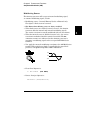
HP 33120A
Function Generator /
Arbitrary Waveform Generator
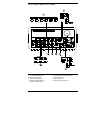
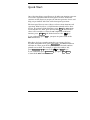
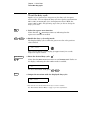
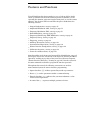
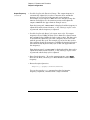
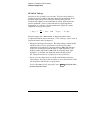
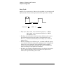
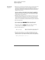
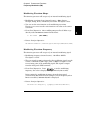
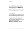
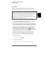
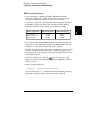
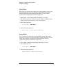
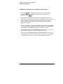
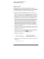
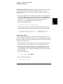
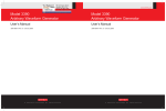
The Front Panel at a Glance
1
2
3
4
2
Function / Modulation keys
Menu operation keys
Waveform modify keys
Single / Internal Trigger key
(Burst and Sweep only)
5
6
7
8
Recall / Store instrument state key
Enter Number key
Shift / Local key
Enter Number “units” keys
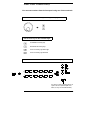
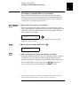
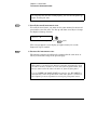
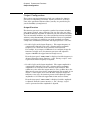
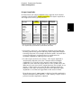
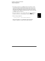
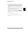
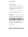
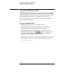
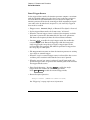
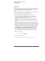
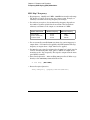
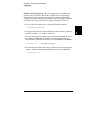
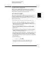
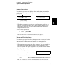
Front-Panel Number Entry
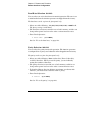
You can enter numbers from the front-panel using one of three methods.
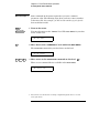
Use the knob and the arrow keys to modify the displayed number.
Use the arrow keys to edit individual digits.
Increments the flashing digit.
Decrements the flashing digit.
Moves the flashing digit to the right.
Moves the flashing digit to the left.
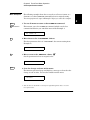
Use the “Enter Number” mode to enter a number with the appropriate units.
Use “Enter” for those operations that do not
require units to be specified (AM Level,
Offset, % Duty, and Store/Recall State).
3
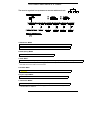
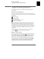
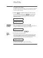
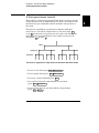
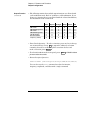
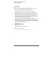
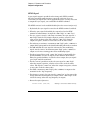
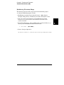
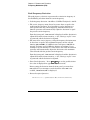
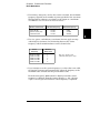
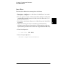
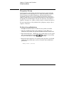
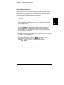
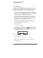
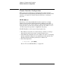
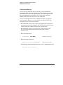
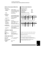
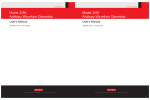
The Front-Panel Menu at a Glance
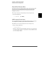
The menu is organized in a top-down tree structure with three levels.
A: MODulation MENU
2: AM SOURCE 3: FM SHAPE 4: BURST CNT 5: BURST RATE
6: BURST PHAS 7: BURST SRC 8: FSK FREQ 9: FSK RATE 10: FSK SRC
1: AM SHAPE
B: SWP (Sweep) MENU
1: START F
2: STOP F 3: SWP TIME 4: SWP MODE
C: EDIT MENU*
1: NEW ARB
[ 2: POINTS ]
[ 3: LINE EDIT ]
[ 4: POINT EDIT ]
[ 5: INVERT ]
[ 6: SAVE AS ] 7: DELETE
* The commands enclosed in square brackets ( [ ] ) are “hidden” until you make a selection from the
NEW ARB command to initiate a new edit session.
D: SYStem MENU
2: POWER ON 3: ERROR 4: TEST 5: COMMA 6: REVISION
1: OUT TERM
E: Input / Output MENU
1: HPIB ADDR
2: INTERFACE 3: BAUD RATE 4: PARITY 5: LANGUAGE
F: CALibration MENU*
1: SECURED
[ 1: UNSECURED ] [ 2: CALIBRATE ] 3: CAL COUNT 4: MESSAGE
* The commands enclosed in square brackets ( [ ] ) are “hidden” unless the function generator
is UNSECURED for calibration.
4
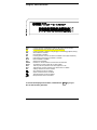
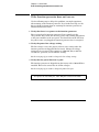
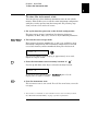
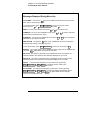
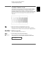
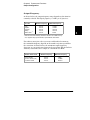
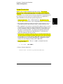
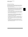
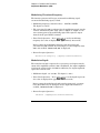
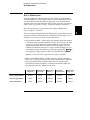
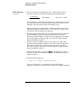
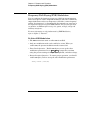
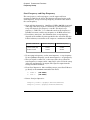
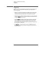
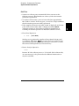
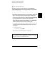
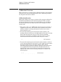
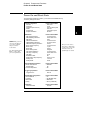
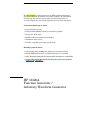
Display Annunciators
Adrs
Rmt
Trig
AM
FM
Ext
FSK
Burst
Swp
ERROR
Offset
Shift
Num
Arb
Function generator is addressed to listen or talk over a remote interface.
Function generator is in remote mode (remote interface).
Function generator is waiting for a single trigger or external trigger (Burst, Sweep).
AM modulation is enabled.
FM modulation is enabled.
Function generator is set for an external modulation source (AM, FSK, Burst).
FSK (frequency-shift keying) modulation is enabled.
Burst modulation is enabled.
Sweep mode is enabled.
Hardware or remote interface command errors are detected.
The waveform is being output with an offset voltage.
“Shift” key has been pressed. Press “Shift” again to turn off.
“Enter Number” mode is enabled. Press “Shift-Cancel” to disable.
Arbitrary waveform function is enabled.
Sine waveform function is enabled.
Square waveform function is enabled.
Triangle waveform function is enabled.
Ramp waveform function is enabled.
To review the display annunciators, hold down the Shift key as you
turn on the function generator.
5
1
1
Quick Start
Quick Start
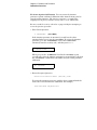
One of the first things you will want to do with your function generator
is to become acquainted with its front panel. We have written the
exercises in this chapter to prepare the function generator for use and
help you get familiar with some of the front-panel operations.
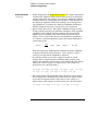
The front panel has two rows of keys to select various functions and
operations. Most keys have a shifted function printed in blue above
the key. To perform a shifted function, press Shift (the Shift annunciator will turn on). Then, press the key that has the desired label
above it. For example, to select the AM (amplitude modulation)
key).
function, press Shift AM (the shifted version of the
If you accidentally press Shift , just press it again to turn off the
Shift annunciator.
Most keys also have a number printed in green next to the key.
To enable the number mode, press Enter Number (the Num annunciator
will turn on). Then, press the keys that have the desired numbers
printed next to them. For example, to select the number “10”,
and Recall keys).
press Enter Number 1 0 (next to the
If you accidentally press Enter Number , just press Shift Cancel
to turn off the Num annunciator.
14
Chapter 1 Quick Start
To prepare the function generator for use
1
To prepare the function generator for use
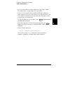
The following steps help you verify that the function generator is
ready for use.
1 Check the list of supplied items.
Verify that you have received the following items with your function
generator. If anything is missing, contact your nearest Hewlett-Packard
Sales Office.
One power cord.
This User’s Guide.
One Service Guide.
One folded Quick Reference card.
Certificate of Calibration.
2 Connect the power cord and turn on the function generator.
The front-panel display will light up while the function generator
performs its power-on self-test. The HP-IB bus address is displayed.
Notice that the function generator powers up in the sine wave function
at 1 kHz with an amplitude of 100 mV peak-to-peak (into a 50Ω
termination).
To review the power-on display with all annunciators turned on,
hold down Shift as you turn on the function generator.
3 Perform a complete self test.
The complete self-test performs a more extensive series of tests than
those performed at power-on. Hold down Shift as you press the Power
switch to turn on the function generator; hold down the key for more
than 5 seconds. The self-test will begin when you release the key.
If the self-test is successful, “PASS” is displayed on the front panel.
If the self-test is not successful, “FAIL” is displayed and the ERROR
annunciator turns on. See the Service Guide for instructions on
returning the function generator to Hewlett-Packard for service.
15
Chapter 1 Quick Start
If the function generator does not turn on
If the function generator does not turn on
Use the following steps to help solve problems you might experience
when turning on the function generator. If you need more help, see the
Service Guide for instructions on returning the function generator to
Hewlett-Packard for service.
1 Verify that there is ac power to the function generator.
First, verify that the function generator’s Power switch is in the
“On” position. Also, make sure that the power cord is firmly plugged into
to the power module on the rear panel. You should also make sure that
the power source you plugged the function generator into is energized.
2 Verify the power-line voltage setting.
The line voltage is set to the proper value for your country when the
function generator is shipped from the factory. Change the voltage
setting if it is not correct. The settings are: 100, 120, 220, or 240 Vac
(for 230 Vac operation, use the 220 Vac setting).
See the next page if you need to change the line-voltage setting.
3 Verify that the power-line fuse is good.
The function generator is shipped from the factory with a 500 mAT fuse
installed. This is the correct fuse for all line voltages.
See the next page if you need to change the power-line fuse.
To replace the 500 mAT fuse, order HP part number 2110-0458.
16
Chapter 1 Quick Start
If the function generator does not turn on
1
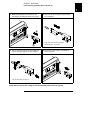
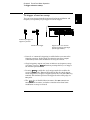
1 Remove the power cord. Remove the
fuse-holder assembly from the rear panel.
2 Remove the line-voltage selector from
the assembly.
Fuse: 500 mAT (for all line voltages)
HP Part Number: 2110-0458
3 Rotate the line-voltage selector until the
correct voltage appears in the window.
4 Replace the fuse-holder assembly in
the rear panel.
100, 120, 220 (230), or 240 Vac
Verify that the correct line voltage is selected and the power-line fuse is good.
17
Chapter 1 Quick Start
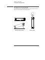
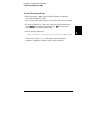
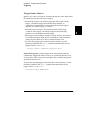
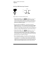
To adjust the carrying handle
To adjust the carrying handle
To adjust the position, grasp the handle by the sides and pull outward.
Then, rotate the handle to the desired position.
Bench-top viewing positions
18
Carrying position
Chapter 1 Quick Start
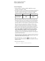
To set the output frequency
1
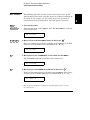
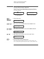
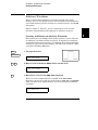
To set the output frequency
At power-on, the function generator outputs a sine wave at 1 kHz with
an amplitude of 100 mV peak-to-peak (into a 50Ω termination).
The following steps show you how to change the frequency to 1.2 MHz.
Freq
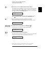
1 Enable the frequency modify mode.
The displayed frequency is either the power-on value or the previous
frequency selected. When you change functions, the same frequency is
used if the present value is valid for the new function.
1.000,000,0 KHz
Enter Number
1
.
2
2 Enter the magnitude of the desired frequency.
1
Notice that the Num annunciator turns on and “ENTER NUM” flashes on
the display, indicating that the number mode is enabled.
1.2
To cancel the number mode, press Shift Cancel .
∧
MHz
m Vpp
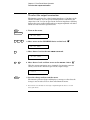
3 Set the units to the desired value.
The units are selected using the arrow keys on the right side of the
front panel. As soon as you select the units, the function generator
outputs the waveform with the displayed frequency. To turn off the
flashing digit, move the cursor to the left of the display using the arrow keys.
1.200,000,0 MHz
1 You can also use the knob and arrow keys to enter a number.
See “Front-Panel Number Entry” on page 3 for more information.
19
Chapter 1 Quick Start
To set the output amplitude
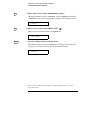
To set the output amplitude
At power-on, the function generator outputs a sine wave with an
amplitude of 100 mV peak-to-peak (into a 50Ω termination).
The following steps show you how to change the amplitude to 50 mVrms.
Ampl
1 Enable the amplitude modify mode.
The displayed amplitude is either the power-on value or the previous
amplitude selected. When you change functions, the same amplitude is
used if the present value is valid for the new function.
100.0
Enter Number
5
0
mVPP
2 Enter the magnitude of the desired amplitude.
1
Notice that the Num annunciator turns on and “ENTER NUM” flashes on
the display, indicating that the number mode is enabled.
50
To cancel the number mode, press Shift Cancel .
Shift
∨
3 Set the units to the desired value.
kHz
m Vrms
The units are selected using the arrow keys on the right side of the
front panel. As soon as you select the units, the function generator
outputs the waveform with the displayed amplitude. To turn off the
flashing digit, move the cursor to the left of the display using the arrow keys.
50.00
mVRMS
1 You can also use the knob and arrow keys to enter a number.
See “Front-Panel Number Entry” on page 3 for more information.
20
Chapter 1 Quick Start
To set a dc offset voltage
1
To set a dc offset voltage
At power-on, the function generator outputs a sine wave with a dc offset
voltage of 0 volts (into a 50Ω termination). The following steps show you
how to change the offset to –1.5 mVdc.
Offset
1 Enable the offset modify mode.
The displayed offset voltage is either the power-on value or the previous
offset selected. When you change functions, the same offset is used if the
present value is valid for the new function.
+0.000
Enter Number
±
1
.
VDC
2 Enter the magnitude of the desired offset.
5
1
Notice that the Num annunciator turns on and “ENTER NUM” flashes
on the display, indicating that the number mode is enabled. Notice
that ± toggles the displayed value between + and – .
-1.5
To cancel the number mode, press Shift Cancel .
Shift
∨
3 Set the units to the desired value.
kHz
m Vrms
At this point, the function generator outputs the waveform with the
displayed offset. Notice that the Offset annunciator turns on, indicating
that the waveform is being output with an offset. The annunciator will
turn on when the offset is any value other than 0 volts. To turn off the
flashing digit, move the cursor to the left of the display using the arrow keys.
-01.50
mVDC
1 You can also use the knob and arrow keys to enter a number.
See “Front-Panel Number Entry” on page 3 for more information.
21
Chapter 1 Quick Start
To set the duty cycle
To set the duty cycle
Applies only to square waves. At power-on, the duty cycle for square
waves is 50%. You can adjust the duty cycle for a square waveform from
20% to 80%, in increments of 1% (for frequencies above 5 MHz, the
range is 40% to 60%). The following steps show you how to change the
duty cycle to 45%.
1 Select the square wave function.
Notice that the
annunciator turns on, indicating that the
square wave function is enabled.
Shift
% Duty
2 Enable the duty cycle modify mode.
The displayed duty cycle is either the power-on value or the previous
value selected.
50 % DUTY
This message appears on the display for approximately 10 seconds.
Repeat this step as needed.
Enter Number
4
5
3 Enter the desired duty cycle.
1
Notice that the Num annunciator turns on and “ENTER NUM” flashes on
the display, indicating that the number mode is enabled.
45
To cancel the number mode, press Shift Cancel .
Enter
4 Output the waveform with the displayed duty cycle.
45 % DUTY
1 You can also use the knob and arrow keys to enter a number.
See “Front-Panel Number Entry” on page 3 for more information.
22
Chapter 1 Quick Start
To output a stored arbitrary waveform
1
To output a stored arbitrary waveform
There are five built-in arbitrary waveforms stored in non-volatile
memory for your use. You can output these waveforms directly from
non-volatile memory. The following steps show you how to output an
“exponential rise” waveform from memory.
Shift
Arb List
1 Display the list of arbitrary waveforms.
The list contains the five built-in arbitrary waveforms (sinc, negative
ramp, exponential rise, exponential fall, and cardiac). The list may also
contain up to four user-defined arbitrary waveform names. The first
choice on this level is “SINC”.
SINC
This message appears on the display for approximately 10 seconds.
Repeat this step as needed.
>
>
2 Move across to the EXP_RISE choice.
1
EXP_RISE
Enter
3 Select and output the displayed arbitrary waveform.
Notice that the Arb annunciator turns on, indicating that the output is
an arbitrary waveform. The waveform is output using the present
settings for frequency, amplitude, and offset unless you change them.
The selected waveform is now assigned to the Arb key. Whenever
you press this key, the selected arbitrary waveform is output.
1 You can also use the knob to scroll left or right through the choices in the list.
See “Front-Panel Number Entry” on page 3 for more information.
23
Chapter 1 Quick Start
To output a dc voltage
To output a dc voltage
In addition to generating waveforms, you can also output a dc voltage in
the range ± 5 Vdc (into a 50Ω termination). The following steps show
you how to output +155 mVdc.
1 Press the Offset
key and hold it down for more than 2 seconds.
To enter the dc voltage mode, press the Offset key or any key in the
top row of function keys and hold it down for more than 2 seconds.
The displayed voltage is either the power-on value or the previous
offset voltage selected.
DCV
+0.000
Enter Number
1
5
5
VDC
2 Enter the magnitude of the desired voltage.
1
Notice that the Num annunciator turns on and “ENTER NUM” flashes on
the display, indicating that the number mode is enabled.
155
To cancel the number mode, press Shift Cancel .
Shift
∨
3 Set the units to the desired value.
kHz
m Vrms
At this point, the function generator outputs the displayed dc voltage.
Notice that the Offset annunciator turns on (all other annunciators
are off), indicating that a dc voltage is being output. The annunciator
will turn on when the offset is any value other than 0 volts.
+155.0
mVDC
1 You can also use the knob and arrow keys to enter a number.
See “Front-Panel Number Entry” on page 3 for more information.
24
Chapter 1 Quick Start
To store the instrument state
1
To store the instrument state
You can store up to three different instrument states in non-volatile
memory. This enables you to recall the entire instrument configuration
with just a few key presses from the front panel. The following steps
show you how to store and recall a state.
1 Set up the function generator to the desired configuration.
The state storage feature “remembers” the function, frequency,
amplitude, dc offset, duty cycle, as well as any modulation parameters.
Shift
Store
2 Turn on the state storage mode.
Three memory locations (numbered 1, 2, and 3) are available to store
instrument configurations. The instrument configuration is stored in
non-volatile memory and is remembered when power has been off.
STORE
1
This message appears on the display for approximately 10 seconds.
Repeat this step as needed.
∧
3 Store the instrument state in memory location “2”.
1
Use the up and down arrow keys to select the memory location.
STORE
2
To cancel the store operation, press Shift Store again or let the
display time-out after 10 seconds.
Enter
4 Save the instrument state.
The instrument state is now stored. To recall the stored state, turn to the
next page.
1 You can also use the knob or “enter number” mode to enter a memory location.
See “Front-Panel Number Entry” on page 3 for more information.
25
Chapter 1 Quick Start
To store the instrument state
To verify that the state was stored properly, you can turn the power off
before recalling the state.
Recall
5 Recall the stored instrument state.
To recall the stored state, you must use the same memory location used
previously to store the state. Use the up and down arrow keys to change
the displayed storage location.
RECALL
2
To cancel the restore operation, press Recall again.
This message appears on the display for approximately 10 seconds.
Repeat this step as needed.
Enter
6 Restore the instrument state.
The function generator should now be configured in the same state as
when you stored the setup on the previous page.
When power is turned off, the function generator automatically stores
its state in memory location “0”. You can recall the power-down state,
but you cannot store the state to location “0” from the front panel.
Use the POWER ON LAST STATE command in the SYS MENU to
automatically recall the power-down state when power is turned on.
See chapter 2 for more information on using the front-panel menus.
26
2
2
Front-Panel
Menu Operation
Front-Panel Menu Operation
By now you should be familiar with some of the basic features of the
front panel. Chapter 1 shows you how to prepare the function generator
for use and describes a few of the front-panel features. If you are not
familiar with this information, we recommend that you read chapter 1,
“Quick Start,” starting on page 13.
Chapter 2 introduces you to the use of the front-panel menu. This chapter
does not give a detailed description of every front-panel key or menu
operation. It does, however, give you a good overview of the front-panel
menu and many front-panel operations. See chapter 3 “Features and
Functions,” starting on page 53, for a complete discussion of the function
generator’s capabilities and operation.
If you purchased the Phase-Lock Option for the HP 33120A,
an additional menu (G: PHASE MENU) is available from the front panel.
For information on using the Phase-Lock Option, refer to the User’s and
Service Guide included with Option 001.
30
Chapter 2 Front-Panel Menu Operation
Front-panel menu reference
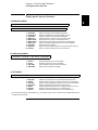
Front-panel menu reference
A: MODulation MENU
1: AM SHAPE
2
2: AM SOURCE 3: FM SHAPE 4: BURST CNT 5: BURST RATE
6: BURST PHAS 7: BURST SRC 8: FSK FREQ 9: FSK RATE 10: FSK SRC
1:
2:
3:
4:
5:
6:
7:
8:
9:
10:
AM SHAPE
AM SOURCE
FM SHAPE
BURST CNT
BURST RATE
BURST PHAS
BURST SRC
FSK FREQ
FSK RATE
FSK SRC
Selects the shape of the AM modulating waveform.
Enables or disables the internal AM modulating source.
Selects the shape of the FM modulating waveform.
Sets the number of cycles per burst (1 to 50,000 cycles).
Sets the burst rate in Hz for an internal burst source.
Sets the starting phase angle of a burst (-360 to +360 degrees).
Selects an internal or external gate source for burst modulation.
Sets the FSK “hop” frequency.
Selects the internal FSK rate between the carrier and FSK frequency.
Selects an internal or external source for the FSK rate.
B: SWP (Sweep) MENU
1: START F
2: STOP F 3: SWP TIME 4: SWP MODE
1:
2:
3:
4:
START F
STOP F
SWP TIME
SWP MODE
Sets the start frequency in Hz for sweeping.
Sets the stop frequency in Hz for sweeping.
Sets the repetition rate in seconds for sweeping.
Selects linear or logarithmic sweeping.
C: EDIT MENU *
1: NEW ARB
[ 2: POINTS ] [ 3: LINE EDIT ] [ 4: POINT EDIT ] [ 5: INVERT ] [ 6: SAVE AS ] 7: DELETE
1:
2:
3:
4:
5:
6:
7:
NEW ARB
POINTS
LINE EDIT
POINT EDIT
INVERT
SAVE AS
DELETE
Initiates a new arb waveform or loads the selected arb waveform.
Sets the number of points in a new arb waveform (8 to 16,000 points).
Performs a linear interpolation between two points in the arb waveform.
Edits the individual points of the selected arb waveform.
Inverts the selected arb waveform by changing the sign of each point.
Saves the current arb waveform in non-volatile memory.
Deletes the selected arb waveform from non-volatile memory.
* The commands enclosed in square brackets ( [ ] ) are “hidden” until you make a selection from the NEW ARB command
to initiate a new edit session.
31
Chapter 2 Front-Panel Menu Operation
Front-panel menu reference
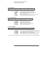
D: SYStem MENU
2: POWER ON 3: ERROR 4: TEST
1: OUT TERM
1:
2:
3:
4:
5:
6:
OUT TERM
POWER ON
ERROR
TEST
COMMA
REVISION
5: COMMA
6: REVISION
Selects the output termination (50Ω or high impedance).
Enables or disables automatic recall of the power-down state.
Retrieves errors from the error queue (up to 20 errors).
Performs a complete self-test.
Enables or disables a comma separator between digits on the display.
Displays the function generator’s firmware revision codes.
E: Input / Output MENU
1: HPIB ADDR
2: INTERFACE 3: BAUD RATE 4: PARITY 5: LANGUAGE
1:
2:
3:
4:
5:
HPIB ADDR
INTERFACE
BAUD RATE
PARITY
LANGUAGE
Sets the HP-IB bus address (0 to 30).
Selects the HP-IB or RS-232 interface.
Selects the baud rate for RS-232 operation.
Selects even, odd, or no parity for RS-232 operation.
Verifies the interface language: SCPI.
F: CALibration MENU *
1: SECURED
[ 1: UNSECURED ] [ 2: CALIBRATE ] 3: CAL COUNT 4: MESSAGE
1:
1:
2:
3:
4:
SECURED
UNSECURED
CALIBRATE
CAL COUNT
MESSAGE
The function generator is secured against calibration; enter code to unsecure.
The function generator is unsecured for calibration; enter code to secure.
Performs individual calibrations; must be UNSECURED.
Reads the total number of times the function generator has been calibrated.
Reads the calibration string (up to 11 characters) entered from remote.
* The commands enclosed in square brackets ( [ ] ) are “hidden” unless the function generator is UNSECURED for calibration.
32
Chapter 2 Front-Panel Menu Operation
A front-panel menu tutorial
A front-panel menu tutorial
This section is a step-by-step tutorial which shows you how to use the
front-panel menu. We recommend that you spend a few minutes with
this tutorial to get comfortable with the structure and operation of
the menu.
2
The menu is organized in a top-down tree structure with three
levels (menus, commands, and parameters). You move down ∨
or up ∧ the menu tree to get from one level to the next. Each of the
three levels has several horizontal choices which you can view by
moving left < or right > .
Menus
Commands
Parameters
The menu is organized in a top-down tree structure with three levels.
• To turn on the menu, press Shift
Menu On/Off
.
• To turn off the menu, press Shift
Menu On/Off
.
• To execute a menu command, press Enter .
• To recall the last menu command that was executed,
press Shift Recall Menu .
• To turn off the menu at any time without saving changes,
press Shift Cancel .
33
Chapter 2 Front-Panel Menu Operation
A front-panel menu tutorial
Messages Displayed During Menu Use
TOP OF MENU You pressed ∧ while on the “MENUS” level; this is the top level of the
menu and you cannot go any higher.
To turn off the menu, press Shift Menu On/Off . To move across the choices
on a level, press < or > . To move down a level, press ∨ .
MENUS You are on the “MENUS” level. Press < or > to view the choices.
COMMANDS You are on the “COMMANDS” level. Press
< or > to view the command
choices within the selected menu group.
PARAMETER You are on the “PARAMETER” level. Press < or > to view and edit the
parameter for the selected command.
MENU BOTTOM You pressed ∨ while on the “PARAMETER” level; this is the bottom
level of the menu and you cannot go any lower.
To turn off the menu, press Shift Menu On/Off . To move up a level, press ∧ .
ENTERED The change made on the “PARAMETER” level is saved. This is displayed after
you press Enter (Menu Enter) to execute the command.
The value you specified on the “PARAMETER” level is too small for the
selected command. The minimum value allowed is displayed for you to edit.
MIN VALUE
The value you specified on the “PARAMETER” level is too large for the
selected command. The maximum value allowed is displayed for you to edit.
MAX VALUE
EXITING You will see this message if you turn off the menu by pressing
Shift Menu On/Off or Shift Cancel . You did not edit any values on the
“PARAMETER” level and changes were NOT saved.
NOT ENTERED You will see this message if you turn off the menu by pressing
Shift Menu On/Off or Shift Cancel . You did some editing of parameters but the
changes were NOT saved. Press the Enter key (Menu Enter) to save changes
made on the “PARAMETER” level.
34
Chapter 2 Front-Panel Menu Operation
A front-panel menu tutorial
Menu Example 1
Shift
The following steps show you how to turn on the menu, move up and
down between levels, move across the choices on each level, and turn off
the menu. In this example, you will enable the function generator to
automatically recall the power-down state when power is turned on.
1 Turn on the menu.
Menu On/Off
You enter the menu on the “MENUS” level. The MOD MENU is your first
choice on this level.
A: MOD MENU
>
>
>
2 Move across to the SYS MENU choice on this level.
1
There are six menu group choices available on the “MENUS” level. Each
choice has a letter prefix for easy identification (A: , B: , etc.).
D: SYS MENU
∨
3 Move down to the “COMMANDS” level within the SYS MENU.
The OUT TERM command is your first choice on this level.
1: OUT TERM
>
4 Move across to the POWER ON command on this level.
1
There are six command choices available in the SYS MENU. Each choice
on this level has a number prefix for easy identification (1: , 2: , etc.).
2: POWER ON
1 You can also use the knob to scroll left or right through the choices on each
level of the menu.
35
2
Chapter 2 Front-Panel Menu Operation
A front-panel menu tutorial
∨
5 Move down a level to the “PARAMETER” choices.
The first parameter choice is “DEFAULT” for the POWER ON command
(“DEFAULT” is the factory setting and is stored in non-volatile memory).
DEFAULT
>
6 Move across to the “LAST STATE” choice.
1
There are two parameter choices for POWER ON.
LAST STATE
Enter
7 Save the change and turn off the menu.
The function generator beeps and displays a message to show that the
change is now in effect. You are then exited from the menu.
ENTERED
1 You can also use the knob to scroll left or right through the choices on each
level of the menu.
36
Chapter 2 Front-Panel Menu Operation
A front-panel menu tutorial
Menu Example 2
The following example shows how to use the recall menu feature as a
shortcut to set the POWER ON command back to its original setting.
You must perform the steps in Example 1 before you start this example.
2
Shift
<
1 Use recall menu to return to the POWER ON command.
Recall Menu
This returns you to the POWER ON command, which was the last
command used before you exited the menu in the Example 1.
2: POWER ON
∨
2 Move down to the “PARAMETER” choices.
The first parameter choice is “LAST STATE” (the current setting from
Example 1).
LAST STATE
>
3 Move across to the “DEFAULT” choice.
1
Set the parameter back to its original value.
DEFAULT
Enter
4 Save the change and turn off the menu.
The function generator beeps and displays a message to show that the
change is now in effect. You are then exited from the menu.
ENTERED
1 You can also use the knob to scroll left or right through the choices on each
level of the menu.
37
Chapter 2 Front-Panel Menu Operation
A front-panel menu tutorial
Menu Example 3
Shift
Some commands in the menu require that you enter a numeric
parameter value. The following steps show you how to enter a number
in the menu. For this example, you will set the number of cycles for the
burst modulation mode.
1 Turn on the menu.
Menu On/Off
You enter the menu on the “MENUS” level. The MOD MENU is your first
choice on this level.
A: MOD MENU
∨
2 Move down to the “COMMANDS” level within the MOD MENU.
The AM SHAPE command is your first choice on this level.
1: AM SHAPE
>
>
>
3 Move across to the BURST CNT command on this level.
1
There are ten command choices available in the MOD MENU.
4: BURST CNT
1 You can also use the knob to scroll left or right through the choices on each
level of the menu.
38
Chapter 2 Front-Panel Menu Operation
A front-panel menu tutorial
∨
4 Move down a level to edit the BURST CNT parameter.
The number of cycles should be “1” when you come to this point in the
menu for the first time. For this example, you will set the number of
cycles to “4”. Notice that the Burst annunciator flashes, indicating that
the displayed value is for the burst mode.
∧00001
2
CYC
When you see the flashing “∧” on the left side of the display, you can
press ∧ to abort the edit and return to the “COMMANDS” level.
<
5 Move the flashing cursor over to edit the last digit.
Notice that the rightmost digit is flashing (the digit wraps around).
00001
∧
∧
∧
CYC
6 Increment the last digit until “4” is displayed.
1
You decrement or increment each digit independently.
00004
Enter
CYC
7 Save the change and turn off the menu.
The function generator beeps and displays a message to show that the
change is now in effect. You are then exited from the menu.
ENTERED
1 You can also use the knob or “enter number” mode to enter a number.
See “Front-Panel Number Entry” on page 3 for more information.
39
Chapter 2 Front-Panel Menu Operation
To select the output termination
To select the output termination
The function generator has a fixed output impedance of 50 ohms on the
OUTPUT terminal. You can specify whether you are terminating the
output into a 50Ω load or an open circuit. Incorrect impedance matching
between the source and load will result in an output amplitude or dc offset
which does not match the specified value.
Shift
1 Turn on the menu.
Menu On/Off
A: MOD MENU
>
>
>
2 Move across to the SYS MENU choice on this level.
1
D: SYS MENU
∨
3 Move down a level to the OUT TERM command.
1: OUT TERM
∨
>
4 Move down a level and then across to the HIGH Z choice.
1
With the output termination set to “HIGH Z”, the function generator
allows you to set the unloaded (open circuit) output voltage.
HIGH Z
Enter
5 Save the change and turn off the menu.
The function generator beeps and displays a message to show that the
change is now in effect. You are then exited from the menu.
1 You can also use the knob to scroll left or right through the choices on each
level of the menu.
40
Chapter 2 Front-Panel Menu Operation
To output a modulated waveform
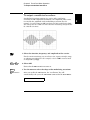
To output a modulated waveform
A modulated waveform consists of a carrier and a modulating
waveform. In AM (amplitude modulation), the amplitude of the carrier
is varied by the amplitude of the modulating waveform. For this
example, you will output an AM waveform with 80% modulation depth.
The carrier will be a 5 kHz sine wave and the modulating waveform will
be a 200 Hz sine wave.
1 Select the function, frequency, and amplitude of the carrier.
For the carrier waveform, you can select a sine, square, triangle, ramp,
or arbitrary waveform. For this example, select a 5 kHz sine wave with
an amplitude of 5 Vpp.
Shift
AM
2 Select AM.
Notice that the AM annunciator turns on.
Shift
<
3 Use the menu to select the shape of the modulating waveform.
Recall Menu
After you enable the AM function, the “recall menu” key will
automatically take you to the AM SHAPE command in the MOD MENU.
1: AM SHAPE
41
2
Chapter 2 Front-Panel Menu Operation
To output a modulated waveform
∨
4 Move down a level and verify that “SINE” is selected.
For the modulating waveform, you can select a sine, square, triangle,
ramp, noise, or arbitrary waveform. For this example, you will modulate
the carrier with a sine waveform. Notice that the AM annunciator
flashes, indicating that the displayed parameter is for AM.
SINE
Enter
5 Save the change and turn off the menu.
The modulating waveform is now a sine waveform.
ENTERED
Shift
Freq
6 Set the modulating frequency to 200 Hz.
Notice that the AM annunciator flashes, indicating that the displayed
frequency is the modulating frequency for AM. Also notice that the
modulating frequency is displayed with fewer digits than the carrier
frequency. For more information on editing numbers in the menu,
refer to “Menu Example 3” earlier in this chapter.
MOD
200.0
Hz
This message appears on the display for approximately 10 seconds.
Repeat this step as needed.
42
Chapter 2 Front-Panel Menu Operation
To output a modulated waveform
Shift
Level
7 Set the modulation depth to 80%.
Notice that the AM annunciator flashes, indicating that the displayed
percentage is the AM depth (also called percent modulation).
080
%
2
DEPTH
This message appears on the display for approximately 10 seconds.
Repeat this step as needed.
At this point, the function generator outputs the AM waveform with the
specified modulation parameters.
43
Chapter 2 Front-Panel Menu Operation
To output an FSK waveform
To output an FSK waveform
You can configure the function generator to “shift” its output frequency
between two preset values using FSK (frequency-shift keying) modulation.
The rate at which the output shifts between the two frequencies
(called the “carrier frequency” and the “hop frequency”) is determined by
the internal rate generator or the signal level on the rear-panel FSK
terminal. For this example, you will set the “carrier” frequency to 3 kHz and
the “hop” frequency to 500 Hz, with an FSK rate of 100 Hz.
1 Select the function, frequency, and amplitude of the carrier.
For the carrier waveform, you can select a sine, square, triangle, ramp,
or arbitrary waveform. For this example, select a 3 kHz sine wave with
an amplitude of 5 Vpp.
Shift
FSK
2 Enable FSK.
Notice that the FSK annunciator turns on.
Shift
<
Recall Menu
3 Use the menu to set the “hop” frequency.
After you enable the FSK mode, the “recall menu” key will automatically
take you to the FSK FREQ command in the MOD MENU.
8: FSK FREQ
44
Chapter 2 Front-Panel Menu Operation
To output an FSK waveform
∨
4 Move down a level and set the “hop” frequency to 500 Hz.
Notice that the FSK annunciator flashes, indicating that the displayed
parameter is for the FSK mode. Also notice that the hop frequency is
displayed with fewer digits than the carrier frequency. For more
information on editing numbers in the menu, refer to “Menu Example 3”
earlier in this chapter.
∧500.0
Enter
Hz
5 Save the change and turn off the menu.
At this point, the carrier and hop frequencies are set and output.
Now, we will go back into the menu to set the FSK “shift” rate — this is
the rate at which the function generator shifts between the carrier
frequency and hop frequency.
Shift
<
6 Use the menu to set the FSK “shift” rate.
Recall Menu
The “recall menu” key returns you to the FSK FREQ command, which
was the last command used before you exited the menu.
8: FSK FREQ
45
2
Chapter 2 Front-Panel Menu Operation
To output an FSK waveform
>
7 Move across to the FSK RATE command.
9: FSK RATE
∨
8 Move down a level and set the FSK “shift” rate to 100 Hz.
Notice that the FSK annunciator flashes, indicating that the displayed
parameter is for the FSK mode. For more information on editing
numbers in the menu, refer to “Menu Example 3” earlier in this chapter.
∧100.0
Enter
Hz
9 Save the change and turn off the menu.
The function generator beeps and displays a message to show that the
change is now in effect. You are then exited from the menu.
ENTERED
At this point, the function generator outputs the FSK waveform.
You can also use an external signal to shift between the carrier frequency
and hop frequency. For more information, see “Frequency-Shift Keying
(FSK) Modulation” in chapter 3.
46
Chapter 2 Front-Panel Menu Operation
To output a burst waveform
To output a burst waveform
You can configure the function generator to output a waveform with a
specified number of cycles, called a burst. You can output the burst at a
rate determined by the internal rate generator or the signal level on the
rear-panel Ext Trig terminal. For this example, you will output a
three-cycle sine wave. You will not change the other parameters from
their default settings: internal burst source, 0 degree starting phase,
and 100 Hz burst rate.
1 Select the function, frequency, and amplitude for the burst.
For bursts, you can select sine, square, triangle, ramp, or arbitrary
waveforms. For this example, select a 1 kHz sine wave with an output
amplitude of 5 Vpp.
Shift
Burst
2 Enable the burst mode.
Notice that the Burst annunciator turns on.
Shift
<
3 Use the menu to set the burst count.
Recall Menu
After you enable the burst mode, the “recall menu” key will
automatically take you to the BURST CNT command in the MOD MENU.
4: BURST CNT
47
2
Chapter 2 Front-Panel Menu Operation
To output a burst waveform
∨
4 Move down to the parameter level and set the count to “3”.
Notice that the Burst annunciator flashes, indicating that the displayed
parameter is for the burst mode. For more information on editing
numbers in the menu, refer to “Menu Example 3” earlier in this chapter.
∧00003 CYC
You can also select an infinite burst count. Press the right or left arrow
keys until the “CYC” units are flashing. Then, press the down arrow key
to display “INFINITE”.
Enter
5 Save the change and turn off the menu.
The function generator beeps and displays a message to show that the
change is now in effect. You are then exited from the menu.
ENTERED
At this point, the function generator outputs a continuous three-cycle burst.
You can generate a single burst (with the specified burst count)
by pressing the “Single” key from the front panel or applying a trigger
pulse to the rear-panel Ext Trig terminal. For more information,
see “To trigger a burst or sweep” on page 51.
You can also use an external gate signal to turn the output signal
on and off. For more information, see “Burst Modulation” in chapter 3.
48
Chapter 2 Front-Panel Menu Operation
To output a frequency sweep
To output a frequency sweep
In the frequency sweep mode, the function generator “steps” from the
start frequency to the stop frequency at a sweep rate which you specify.
You can sweep up or down in frequency, and with either linear or
logarithmic spacing. For this example, you will output a swept sine wave
from 50 Hz to 5 kHz. You will not change the other parameters from their
default settings: internal sweep trigger, linear spacing, and 1 second
sweep time.
1 Select the function and amplitude for the sweep.
For sweeps, you can select sine, square, triangle, ramp, or arbitrary
waveforms. For this example, select a sine wave with a 5 Vpp amplitude.
Shift
Sweep
2 Enable the sweep mode.
Notice that the Swp annunciator turns on.
Shift
<
3 Use the menu to select the start frequency.
Recall Menu
After you enable the sweep mode, the “recall menu” key will
automatically take you to the START F command in the SWP MENU.
1: START F
49
2
Chapter 2 Front-Panel Menu Operation
To output a frequency sweep
∨
4 Move down a level and set the start frequency to 50 Hz.
Notice that the Swp annunciator flashes, indicating that the displayed
parameter is for the sweep mode. For more information on editing
numbers in the menu, refer to “Menu Example 3” earlier in this chapter.
∧50.00
Enter
Hz
5 Save the change and turn off the menu.
The start frequency is now set to 50 Hz.
Shift
<
6 Use recall menu to return to the START F command.
Recall Menu
The “recall menu” key returns you to the START F command, which was
the last command used before you exited the menu.
1: START F
>
7 Move across to the STOP F command.
2: STOP F
∨
8 Move down a level and set the stop frequency to 5 kHz.
∧5.000
Enter
KHz
9 Save the change and turn off the menu.
At this point, the function generator outputs a continuous sweep from
50 Hz to 5 kHz.
You can generate one frequency sweep by pressing the “Single” key or
applying a trigger pulse to the rear-panel Ext Trig terminal. For more
information, see “To trigger a burst or sweep” on the next page.
50
Chapter 2 Front-Panel Menu Operation
To trigger a burst or sweep
To trigger a burst or sweep
You can issue triggers from the front-panel for burst modulation and
frequency sweeps using single trigger or internal trigger.
2
Enables single trigger and
triggers the generator.
Enables internal trigger.
Trig annunciator is on when the
generator is waiting for single trigger
(internal trigger disabled).
• Internal or “automatic” triggering is enabled when you turn on the
function generator. In this mode, the function generator outputs
continuously when burst modulation or sweep is selected.
• Single triggering outputs one burst or initiates one frequency sweep
each time you press Single . Continue pressing this key to re-trigger
the function generator.
• Pressing Single to enable the single trigger mode also enables the
external trigger mode. External triggering is like the single trigger
mode except that you apply a trigger signal to the rear-panel Ext Trig
terminal. The function generator is triggered on the rising edge of a
TTL pulse.
• The Single key is disabled when in remote (the Rmt annunciator
turns on when in remote) and when a function other than burst
modulation or sweep is selected.
51
Chapter 2 Front-Panel Menu Operation
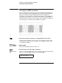
To turn off the comma separator
To turn off the comma separator
The function generator can display values on the front panel with or
without a comma separator. The following steps show how to turn off
the comma separator.
15.000,000 MHz
With comma separator
15.000000 MHz
Without comma separator
(factory setting)
Shift
1 Turn on the menu.
Menu On/Off
A: MOD MENU
>
>
>
2 Move across to the SYS MENU choice on the “MENUS” level.
D: SYS MENU
∨
<
<
3 Move down a level and then across to the COMMA command.
5: COMMA
∨
>
4 Move down a level and then across to the “ OFF” choice.
OFF
Enter
5 Save the change and turn off the menu.
The comma separator setting is stored in non-volatile memory, and
does not change when power has been off or after a remote interface reset.
52
3
3
Features and
Functions
Features and Functions
You will find that this chapter makes it easy to look up all the details
about a particular feature of the function generator. Whether you are
operating the function generator from the front panel or over the remote
interface, this chapter will be useful. This chapter is divided into the
following sections:
• Output Configuration, starting on page 55
• Amplitude Modulation (AM), starting on page 71
• Frequency Modulation (FM), starting on page 76
• Burst Modulation, starting on page 81
• Frequency-Shift Keying (FSK) Modulation, starting on page 90
• Frequency Sweep, starting on page 94
• Triggering, starting on page 98
• Arbitrary Waveforms, starting on page 103
• System-Related Operations, starting on page 109
• Remote Interface Configuration, starting on page 114
• Calibration Overview, starting on page 118
• Power-On and Reset State, on page 123
Some knowledge of the front-panel menu will be helpful before you read
this chapter. If you have not already read chapter 2, “Front-Panel Menu
Operation,” starting on page 29, you may want to read it now. Chapter 4,
“Remote Interface Reference,” starting on page 125, lists the syntax for
the SCPI commands available to program the function generator.
Throughout this manual, the following conventions are used for
SCPI command syntax for remote interface programming.
• Square brackets ( [ ] ) indicate optional keywords or parameters.
• Braces ( { } ) enclose parameters within a command string.
• Triangle brackets ( < > ) indicate that you must substitute a value
for the enclosed parameter.
• A vertical bar ( | ) separates multiple parameter choices.
54
Chapter 3 Features and Functions
Output Configuration
Output Configuration
This section contains information to help you configure the function
generator for outputting waveforms. You may never have to change
some of the parameters discussed here, but they are provided to give
you the flexibility you might need.
Output Function
The function generator can output five standard waveforms including
sine, square, triangle, ramp, and noise. You can also select one of five
predefined arbitrary waveforms or download your own custom waveforms.
You can internally modulate any of the standard waveforms (including
arbitrary) using AM, FM, FSK, or burst modulation. Linear or logarithmic
frequency sweeping is available for any of the standard waveforms
(except noise) and arbitrary waveforms. The default function is sine wave.
• Possible Conflict with Output Frequency: The output frequency is
automatically adjusted if you select a function whose maximum
frequency is less than that of the currently active function.
For example, if you output a 1 MHz sine wave and then change the
function to triangle wave, the function generator will adjust the
output to 100 kHz (the upper limit for triangle waves).
From the front panel, “FREQ LIMIT” is displayed and the frequency is
adjusted. From the remote interface, a -221, “Settings conflict” error
is generated and the frequency is adjusted.
• Possible Conflict with Output Amplitude: The output amplitude is
automatically adjusted if you select a function whose maximum
amplitude is less than that of the currently active function. This
conflict may arise when the output units are Vrms or dBm due to the
differences in crest factor for the output functions. For example, if you
output a 5 Vrms square wave (into 50 ohms) and then change the
function to sine wave, the function generator will adjust the output
amplitude to 3.535 Vrms (the upper limit for sine waves in Vrms).
From the front panel, “AMPL LIMIT” is displayed and the amplitude
is adjusted. From the remote interface, a -221, “Settings conflict”
error is generated and the amplitude is adjusted.
55
3
Chapter 3 Features and Functions
Output Configuration
Output Function
(continued)
• The following matrix shows which output functions are allowed with
each modulation mode. Each “X” indicates a valid combination. If you
change to a function that is not allowed with the selected modulation,
the modulation mode is turned off.
AM Carrier
AM Modulating Wave
FM Carrier
FM Modulating Wave
FSK Modulation
Burst Modulation
Frequency Sweep
Sine
Square
Triangle
Ramp
X
X
X
X
X
X
X
X
X
X
X
X
X
X
X
X
X
X
X
X
X
X
X
X
X
X
X
X
Noise
X
X
Arb
X
X
X
X
X
X
X
• Front-Panel Operation: To select a function, press any key in the top
row of function keys. Press Arb to output the arbitrary waveform
currently selected (to scroll through the waveform choices and
make a selection, press Arb List ).
• To select dc volts from the front panel, press Offset and hold it down
for more than 2 seconds.
• Remote Interface Operation:
FUNCtion:SHAPe {SINusoid|SQUare|TRIangle|RAMP|NOISe|USER|DC}
You can also use the APPLy command to select the function,
frequency, amplitude, and offset with a single command.
56
Chapter 3 Features and Functions
Output Configuration
Output Frequency
As shown below, the output frequency range depends on the function
currently selected. The default frequency is 1 kHz for all functions.
Function
Minimum Frequency
Sine
Square
Triangle
Ramp
Built-In Arbs 1
Maximum Frequency
100 µHz
100 µHz
100 µHz
100 µHz
100 µHz
15 MHz
15 MHz
100 kHz
100 kHz
5 MHz
3
1 There are five built-in arbitrary waveforms stored in non-volatile memory:
sinc, negative ramp, exponential rise, exponential fall, and cardiac.
For arbitrary waveforms that you create and download to memory,
the maximum frequency depends on the number of points specified in
the waveform. As shown below, the maximum output frequency
decreases as you specify more points in the waveform. The five built-in
arbitrary waveforms can be output at a maximum of 5 MHz.
Number of Arb Points
8 to 8,192 (8k)
8,193 to 12,287 (12k)
12,288 to 16,000
Minimum Frequency
100 µHz
100 µHz
100 µHz
Maximum Frequency
5 MHz
2.5 MHz
200 kHz
57
Chapter 3 Features and Functions
Output Configuration
Output Frequency
(continued)
• Possible Conflict with Function Change: The output frequency is
automatically adjusted if you select a function whose maximum
frequency is less than that of the currently active function.
For example, if you output a 1 MHz sine wave and then change the
function to triangle wave, the function generator will adjust the
output to 100 kHz (the upper limit for triangle waves).
From the front panel, “FREQ LIMIT” is displayed and the frequency is
adjusted. From the remote interface, a -221, “Settings conflict” error
is generated and the frequency is adjusted.
• Possible Conflict with Duty Cycle (square wave only): For output
frequencies above 5 MHz, the duty cycle is limited to values between
40% and 60% (below 5 MHz, the range is 20% to 80%). The duty cycle
is automatically adjusted if you select a frequency that is not valid
with the present duty cycle. For example, if you set the duty cycle to
70% and then change the frequency to 8 MHz, the function generator
will automatically adjust the duty cycle to 60% (the upper limit for
this frequency).
From the front panel, “% DUTY LIMIT” is displayed and the duty cycle is
adjusted. From the remote interface, a -221, “Settings conflict” error
is generated and the duty cycle is adjusted.
• Front-Panel Operation: To set the output frequency, press Freq .
Then use the knob, arrow keys, or “Enter Number” mode to set the
frequency.
• Remote Interface Operation:
FREQuency {<frequency>|MINimum|MAXimum}
You can also use the APPLy command to select the function,
frequency, amplitude, and offset with a single command.
58
Chapter 3 Features and Functions
Output Configuration
Output Amplitude
As shown below, the output amplitude range depends on the function
currently selected and the output termination. The default amplitude is
100 mVpp (into 50 ohms) for all functions.
Function
Output
Termination
Minimum
Amplitude
Maximum
Amplitude
Sine
Square
Triangle
Ramp
Noise
Built-In Arbs 1
50Ω
50Ω
50Ω
50Ω
50Ω
50Ω
50 mVpp
50 mVpp
50 mVpp
50 mVpp
50 mVpp
50 mVpp
10 Vpp
10 Vpp
10 Vpp
10 Vpp
10 Vpp
10 Vpp
Sine
Square
Triangle
Ramp
Noise
Built-In Arbs 1
Open Circuit
Open Circuit
Open Circuit
Open Circuit
Open Circuit
Open Circuit
100 mVpp
100 mVpp
100 mVpp
100 mVpp
100 mVpp
100 mVpp
20 Vpp
20 Vpp
20 Vpp
20 Vpp
20 Vpp
20 Vpp
3
1 There are five built-in arbitrary waveforms stored in non-volatile memory:
sinc, negative ramp, exponential rise, exponential fall, and cardiac.
• For arbitrary waveforms, the maximum amplitude will be limited if
the data points do not span the full range of the output DAC (Digitalto-Analog Converter). For example, the built-in “SINC” waveform does
not use the full range of values between ±1 and therefore its
maximum amplitude is 6.084 Vpp (into 50 ohms).
• Possible Conflict with Function Change: The output amplitude is
automatically adjusted if you select a function whose maximum
amplitude is less than that of the currently active function. This
conflict may arise when the output units are Vrms or dBm due to the
differences in crest factor for the output functions. For example, if you
output a 5 Vrms square wave (into 50 ohms) and then change the
function to sine wave, the function generator will adjust the output
amplitude to 3.535 Vrms (the upper limit for sine waves in Vrms).
From the front panel, “AMPL LIMIT” is displayed and the amplitude is
adjusted. From the remote interface, a -221, “Settings conflict” error is
generated and the amplitude is adjusted.
59
Chapter 3 Features and Functions
Output Configuration
Output Amplitude
(continued)
• Output Amplitude and Output Termination: The output amplitude is
automatically adjusted (and no error is generated) if you change the
output termination. For example, if you set the amplitude to 10 Vpp
and then change the termination from 50 ohms to “high impedance”,
the displayed amplitude will double to 20 Vpp. If you change from
“high impedance” to 50 ohms, the displayed amplitude will drop in
half. See “Output Termination” on page 65 for more information.
• Offset Voltage Restrictions: The output amplitude (in Vpp) and the
dc offset voltage must obey the following restrictions. If the specified
amplitude is not valid, the function generator will automatically
adjust it to the maximum value allowed with the present offset
voltage. (Vmax is either 10 volts for a high impedance termination
or 5 volts for a 50 ohm termination; Vpp is the output amplitude in
volts peak-to-peak.)
Voffset +
Vpp
2
≤ Vmax
and
Voffset ≤ 2 x Vpp
From the front panel, “MAX VALUE” is displayed and the amplitude
is adjusted. From the remote interface, a -221, “Settings conflict”
error is generated and the amplitude is adjusted.
• A momentary glitch occurs in the output waveform at certain
voltages due to output attenuator switching. This positive-going
glitch occurs when the output voltage crosses the break-point voltage
either from a lower voltage or a higher voltage. The voltages are
shown below (for a 0 volt dc offset):
252 mVpp, 399 mVpp, 502 mVpp, 796 mVpp, 1 Vpp, 1.59 Vpp,
2.0 Vpp, 3.17 Vpp, 3.99 Vpp, 6.32 Vpp, 7.96 Vpp
• The output voltage will momentarily drop to 0 volts at certain voltages
due to output relay switching. This occurs when the output voltage
crosses the break-point voltage either from a lower voltage or a
higher voltage. The voltages are shown below (for a 0 volt dc offset):
317 mVpp, 632 mVpp, 1.26 Vpp, 2.52 Vpp, 5.02 Vpp
60
Chapter 3 Features and Functions
Output Configuration
• You can set the units for output amplitude to Vpp, Vrms, or dBm.
See “Output Units” on page 64 for more information.
• For dc volts, the output level is actually controlled by setting the
offset voltage. You can set the dc voltage to any value between ±5 Vdc
into 50 ohms or ±10 Vdc into an open circuit. See “DC Offset Voltage”
on page 62 for more information.
To select dc volts from the front panel, press Offset and hold it down
for more than 2 seconds.
3
• Front-Panel Operation: To set the output amplitude, press Ampl .
Then use the knob, arrow keys, or “Enter Number” mode to set the
amplitude.
• Remote Interface Operation:
VOLTage {<amplitude>|MINimum|MAXimum}
You can also use the APPLy command to select the function,
frequency, amplitude, and offset with a single command.
61
Chapter 3 Features and Functions
Output Configuration
DC Offset Voltage
At power-on, the dc offset is set to 0 volts. You can set the offset to a
positive or negative number with the restrictions shown below. If the
specified offset voltage is not valid, the function generator will
automatically adjust it to the maximum dc voltage allowed with the
present amplitude. (Vmax is either 10 volts for a high impedance
termination or 5 volts for a 50 ohm termination; Vpp is the output
amplitude in volts peak-to-peak.)
Voffset +
Vpp
2
≤ Vmax
and
Voffset ≤ 2 x Vpp
From the front panel, “MAX VALUE” is displayed and the offset
is adjusted. From the remote interface, a -221, “Settings conflict” error is
generated and the offset is adjusted.
• DC Offset and Output Termination: The offset voltage is automatically
adjusted (and no error is generated) if you change the output
termination. For example, if you set the offset to 100 mVdc and then
change the termination from 50 ohms to “high impedance”, the
displayed offset will double to 200 mVdc. If you change from “high
impedance” to 50 ohms, the displayed offset will drop in half.
See “Output Termination” on page 65 for more information.
• For dc volts, the output level is actually controlled by setting the
offset voltage. You can set the dc voltage to any value between ±5 Vdc
into 50 ohms or ±10 Vdc into an open circuit.
To select dc volts from the front panel, press Offset and hold it down
for more than 2 seconds.
62
Chapter 3 Features and Functions
Output Configuration
• For arbitrary waveforms, the Offset annunciator will turn on if the
waveform data has an inherent offset present (if the average is not
equal to zero). The function generator calculates the average of the
data points and compares the average to zero volts. If the average is
not within two DAC (Digital-to-Analog Converter) counts of zero volts,
the Offset annunciator turns on.
• Front-Panel Operation: To set the dc offset, press Offset . Then use
the knob, arrow keys, or “Enter Number” mode to set the offset.
• Remote Interface Operation:
3
VOLTage:OFFSet {<offset>|MINimum|MAXimum}
You can also use the APPLy command to select the function,
frequency, amplitude, and offset with a single command.
63
Chapter 3 Features and Functions
Output Configuration
Output Units
Applies only to output amplitude (does not affect offset). At power-on,
the units for output amplitude are volts peak-to-peak.
• Output units: Vpp, Vrms, or dBm. The default is Vpp.
• The unit setting is stored in volatile memory; the units are set to
“Vpp” when power has been off or after a remote interface reset.
• When switching from remote programming over the interface back to
front-panel (local) operation, the output units are remembered.
For example, if you select “Vrms” from the remote interface, the units
are shown as “Vrms” on the front-panel display.
• Front-Panel Operation: Use the “Enter Number” units keys
(the arrow keys located on the right side of the front panel) to select
the output units. You can also convert from one unit to another from
the front panel. For example, to convert 2 Vpp to its equivalent value
in Vrms, press the following keys:
Enter Number
∨
kHz
m Vrms
The converted value is 707.1 mVrms.
• Remote Interface Operation:
VOLTage:UNIT {VPP|VRMS|DBM|DEFault}
64
Chapter 3 Features and Functions
Output Configuration
Output Termination
Applies only to output amplitude and offset voltage. The function
generator has a fixed output impedance of 50 ohms on the OUTPUT
terminal. You can specify whether you are terminating the output into
a 50 ohm load or an open circuit. Incorrect impedance matching between
the function generator and your load will result in an amplitude or
offset which does not match the specified signal level.
• Output termination: 50Ω or High impedance. The default is 50Ω.
See the table on page 59 for a list of amplitude limits for all functions.
3
• The output termination setting is stored in volatile memory; 50Ω is
selected when power has been off or after a remote interface reset.
• The amplitude (or dc offset) is automatically adjusted (and no error is
generated) if you change the output termination. For example, if you
set the amplitude to 10 Vpp and then change the termination from
50 ohms to “high impedance”, the displayed amplitude will double
to 20 Vpp. If you change from “high impedance” to 50 ohms, the
displayed amplitude will drop in half.
• If you specify a 50 ohm termination but are actually terminating into
an open circuit, the displayed output will be twice the value specified.
For example, if you set the offset to 100 mVdc (and specify a 50 ohm
termination) but are actually terminating the output into an open
circuit, the actual displayed offset will be 200 mVdc.
• Front-Panel Operation: Choose “50 OHM” or “HIGH Z” from the
front-panel menu.
1: OUT TERM
(SYS MENU)
• Remote Interface Operation:
OUTPut:LOAD {50|INFinity|MINimum|MAXimum}
65
Chapter 3 Features and Functions
Output Configuration
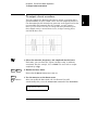
Duty Cycle
Applies only to square waves. Duty cycle is specified as a percentage and
represents the amount of time per cycle that the square wave is high.
TD
T
Duty Cycle =
TD
T
(where T =
1
)
frequency
• Duty cycle: 20% to 80%, in 1% increments (frequency ≤ 5 MHz).
40% to 60%, in 1% increments (frequency > 5 MHz).
The default is 50%.
• The duty cycle is stored in volatile memory; the duty cycle is set to
50% when power has been off or after a remote interface reset.
The APPLy command automatically sets the duty cycle to 50% for
square waves.
• Before attempting to set the duty cycle, you must enable the square
wave function. From the front panel, “SQUARE ONLY” is displayed if
square wave is not currently active. From the remote interface,
no error is generated, but the specified duty cycle is remembered
when you change to the square wave function.
• The duty cycle setting is remembered when you change from square
wave to another function. When you return to the square wave
function, the previous duty cycle is used.
66
Chapter 3 Features and Functions
Output Configuration
• Possible Conflict with Output Frequency: The duty cycle is automatically adjusted if you select a frequency that is not valid with the
present duty cycle. For example, if you set the duty cycle to 70% and
then change the frequency to 8 MHz, the function generator will
automatically adjust the duty cycle to 60% (the upper limit for this
frequency).
From the front panel, “% DUTY LIMIT” is displayed and the duty cycle is
adjusted. From the remote interface, a -221, “Settings conflict” error
is generated and the duty cycle is adjusted.
3
• Front-Panel Operation: To set the duty cycle, press Shift % Duty
(the value appears on the display for approximately 10 seconds).
Then use the knob, arrow keys, or “Enter Number” mode to set the
duty cycle.
• Remote Interface Operation:
PULSe:DCYCle {<percent>|MINimum|MAXimum}
The APPLy command automatically sets the duty cycle to 50% for
square waves.
67
Chapter 3 Features and Functions
Output Configuration
SYNC Signal
A sync signal output is provided on the front-panel SYNC terminal.
All of the standard output functions (except dc and noise) have an
associated sync signal. For certain applications where you may not want
to output the sync signal, you can disable the SYNC terminal.
The SYNC terminal can be enabled/disabled from the remote interface only.
• By default, the sync signal is routed to the SYNC terminal (enabled).
• When the sync signal is disabled, the output level on the SYNC
terminal is indeterminate (it might be a TTL “high” or a TTL “low”).
• For sine, square, triangle, and ramp waveforms, the sync signal is a
TTL “high” when the waveform’s output is positive, relative to zero
volts (or the dc offset value). The signal is a TTL “low” when the
output is negative, relative to zero volts (or the dc offset value).
• For arbitrary waveforms, a momentary TTL “high” pulse (> 200 ns) is
output which corresponds to the first downloaded point in the waveform.
• For AM and FM, the sync signal is referenced to the modulating
signal (not the carrier). A momentary TTL “high” pulse (> 200 ns) is
output at each zero-crossing point of the modulating signal.
• For the triggered burst mode, a TTL “low” signal is output while the
specified number of cycles is output (for the duration of the burst).
After the specified number of cycles has been output, the sync signal
goes “high” until the next burst.
• For the external gated burst mode, the sync signal is a TTL “high”
when the output is positive, relative to zero volts (or the dc offset
value). The signal is a TTL “low” when the output is negative, relative
to zero volts (or the dc offset value).
• For FSK, a momentary TTL “high” pulse (> 200 ns) is output on the
transition to the “hop” frequency.
• For frequency sweeps, the sync signal is a TTL “low” at the start of the
sweep (when the start frequency is output) and is a TTL “high” at the
end of the sweep (when the stop frequency is output).
• Remote Interface Operation:
OUTPut:SYNC {OFF|ON}
68
Setting is stored in volatile memory.
Chapter 3 Features and Functions
Output Configuration
Instrument State Storage
You can store up to three different instrument states in non-volatile
memory. This enables you to recall the entire instrument configuration
with a single command from the remote interface or with just a few
key presses from the front panel.
• Three memory locations (numbered 1, 2, and 3) are available to store
instrument configurations. The state storage feature “remembers” the
function (including arbitrary waveforms), frequency, amplitude,
dc offset, duty cycle, as well as any modulation parameters. To recall
a stored state, you must use the same memory location used
previously to store the state.
• You cannot recall the instrument state from a memory location that
was not previously specified as a storage location. For example, an
error is generated if you attempt to recall from memory location “2”
but have never stored to that location.
From the front panel, “NOT STORED” is displayed if nothing is stored
in the specified memory location. From the remote interface, a
+810, “State has not been stored” error is generated if nothing is
stored in the specified memory location.
• Any arbitrary waveforms downloaded to “VOLATILE” memory are not
remembered. However, if an arbitrary waveform is being output
from non-volatile memory when the state is stored, the waveform
data is stored. The stored waveform is output when the instrument
state is recalled.
• If you delete an arbitrary waveform after storing the state, the
waveform data is lost and the function generator will not output the
waveform when the state is recalled. The “SINC” waveform is output
in place of the deleted waveform.
69
3
Chapter 3 Features and Functions
Output Configuration
State Storage
(continued)
• When power is turned off, the function generator automatically stores
its state in memory location “0”. You can configure the function
generator to automatically recall the power-down state when power is
restored. The recall mode is disabled when the function generator is
shipped from the factory.
Select the POWER ON LAST STATE command from the SYS MENU to
enable the power-down recall mode. Select POWER ON DEFAULT to
disable the power-down recall mode. See “Power-Down Recall Mode”
on page 109 for more information.
• From the remote interface, you can use memory location “0” to store
a fourth instrument configuration (you cannot store to this memory
location from the front panel). However, keep in mind that memory
location “0” is automatically overwritten when the power is turned off.
• Front-Panel Operation:
To store the state, press Shift Store . Then use the knob, arrow
keys, or “Enter Number” mode to select the memory location.
To restore the state, press Recall . Then use the knob, arrow keys,
or “Enter Number” mode to select the memory location.
• Remote Interface Operation:
*SAV {0|1|2|3}
*RCL {0|1|2|3}
State 0 is the instrument state at power down.
States 1, 2, and 3 are user-defined states.
• From the remote interface, you can delete individual stored states
and clear the memory location. If nothing is stored in the specified
memory location, a +810, “State has not been stored” error is generated.
MEMory:STATe:DELete {0|1|2|3}
70
Chapter 3 Features and Functions
Amplitude Modulation (AM)
Amplitude Modulation (AM)
A modulated waveform consists of a carrier waveform and a modulating
waveform. In AM, the amplitude of the carrier is varied by the amplitude
of the modulating waveform. The function generator will accept an
internal modulating signal, an external modulating signal, or both.
For more information on the fundamentals of Amplitude Modulation,
refer to chapter 7, “Tutorial”.
3
To Select AM Modulation
• The AM annunciator turns on when AM is enabled.
• Only one modulation mode can be enabled at a time. When you
enable AM, the previous modulation mode is turned off.
• Front-Panel Operation: Enable AM before setting up the other
modulation parameters. Press Shift AM to output an AM waveform
using the present settings for the carrier frequency, modulating
frequency, output amplitude, and offset voltage.
• Remote Interface Operation: To ensure proper operation, you should
enable AM after you have set up the other modulation parameters.
AM:STATe {OFF|ON}
71
Chapter 3 Features and Functions
Amplitude Modulation (AM)
Carrier Waveform Shape
• AM carrier shape: Sine, Square, Triangle, Ramp, or Arbitrary
waveform. The default is Sine.
• You cannot use the noise function or dc volts as the carrier waveform.
• Front-Panel Operation: Press any of the front-panel function keys
except Noise . For arbitrary waveforms, the Arb key selects the
waveform that is currently downloaded.
• Remote Interface Operation:
FUNCtion:SHAPe {SINusoid|SQUare|TRIangle|RAMP|USER}
You can also use the APPLy command to select the function,
frequency, amplitude, and offset with a single command.
Carrier Frequency
• Carrier frequency: 100 µHz to 15 MHz (100 kHz for triangle and ramp).
The default is 1 kHz.
• For arbitrary waveforms, the maximum carrier frequency depends on
the number of points specified in the waveform. The five built-in
arbitrary waveforms can be output at a maximum of 5 MHz.
Number of Arb Points
Minimum Frequency
8 to 8,192 (8k)
8,193 to 12,287 (12k)
12,288 to 16,000
Maximum Frequency
100 µHz
100 µHz
100 µHz
5 MHz
2.5 MHz
200 kHz
• Front-Panel Operation: Press the Freq key to select any valid
frequency for the selected function (the present amplitude and offset
voltage are used).
• Remote Interface Operation:
FREQuency {<frequency>|MINimum|MAXimum}
72
Chapter 3 Features and Functions
Amplitude Modulation (AM)
Modulating Waveform Shape
The function generator will accept an internal modulating signal,
an external modulating signal, or both.
• Modulating waveform shape (internal source): Sine, Square,
Triangle, Ramp, Noise, or Arbitrary waveform. The default is Sine.
• You can use the noise function as the modulating waveform.
However, you cannot use the noise function or dc volts as the
carrier waveform.
• Front-Panel Operation: After enabling AM, press Recall Menu to go
directly to the AM SHAPE command in the menu.
1: AM SHAPE
3
(MOD MENU)
• Remote Interface Operation:
AM:INTernal:FUNCtion {SINusoid|SQUare|TRIangle|RAMP|NOISe|USER}
73
Chapter 3 Features and Functions
Amplitude Modulation (AM)
Modulating Waveform Frequency
The function generator will accept an internal modulating signal,
an external modulating signal, or both.
• Modulating frequency (internal source): 10 mHz to 20 kHz.
The default is 100 Hz.
• The sync signal for AM is referenced to the modulating signal (not the
carrier). A momentary TTL “high” pulse (> 200 ns) is output at each
zero-crossing point of the modulating signal. The signal is output
from the front-panel SYNC terminal.
• Front-Panel Operation: Press Shift Freq to set the modulating
frequency (the value is displayed for approximately 10 seconds).
Before setting the modulating frequency from the front panel,
you must have AM enabled. If you attempt to set the frequency when
AM is not enabled, “SELECT AM, FM” is displayed.
• Remote Interface Operation:
AM:INTernal:FREQuency {<frequency>|MINimum|MAXimum}
Modulation Depth
The modulation depth is expressed as a percentage and represents the
extent of the amplitude variation. At 0% modulation, the output amplitude
is half of the selected value. At 100% modulation, the output amplitude
equals the selected value.
• Modulation depth: 0% to 120%. The default is 100%.
• Front-Panel Operation: Press Shift Level to set the depth in percent
(the value is displayed for approximately 10 seconds).
Before setting the modulation depth from the front panel, you must
have AM enabled. If you attempt to set the depth when AM is not
enabled, “SELECT AM, FM” is displayed.
• Remote Interface Operation:
AM:DEPTh {<depth in percent>|MINimum|MAXimum}
74
Chapter 3 Features and Functions
Amplitude Modulation (AM)
Modulating Source
The function generator will accept an internal modulating signal,
an external modulating signal, or both.
• Modulating source: Internal-External (both) or External only.
The default is Both (internal-external).
• The External modulating source is always enabled.
• When both sources are enabled (internal-external), the function
generator adds the internal and external modulating signals
(the carrier waveform is actually modulated with two waveforms).
3
• When the internal source is disabled (external only), the carrier
waveform is modulated with the external waveform. The Ext
annunciator turns on to indicate that the function generator is
expecting a modulating signal on the rear-panel AM Modulation
terminal.
• You apply the external modulating waveform to the AM Modulation
terminal. The modulation depth is controlled by the signal level
present (5 volts peak corresponds to 100% modulation).
5V
0V
-5 V
• Front-Panel Operation:
2: AM SOURCE
(MOD MENU)
• Remote Interface Operation:
AM:SOURce {BOTH|EXTernal}
75
Chapter 3 Features and Functions
Frequency Modulation (FM)
Frequency Modulation (FM)
A modulated waveform consists of a carrier waveform and a modulating
waveform. In FM, the frequency of the carrier is varied by the amplitude
of the modulating waveform. The function generator will accept only an
internal FM modulating signal (no external source is available).
For more information on the fundamentals of Frequency Modulation,
refer to chapter 7, “Tutorial”.
To Select FM Modulation
• The FM annunciator turns on when FM is enabled.
• Only one modulation mode can be enabled at a time. When you
enable FM, the previous modulation mode is turned off.
• Front-Panel Operation: Enable FM before setting up the other
modulation parameters. Press Shift FM to output an FM waveform
using the present settings for the carrier frequency, modulating
frequency, output amplitude, and offset voltage.
• Remote Interface Operation: To ensure proper operation, you should
enable FM after you have set up the other modulation parameters.
FM:STATe {OFF|ON}
76
Chapter 3 Features and Functions
Frequency Modulation (FM)
Carrier Waveform Shape
• FM carrier shape: Sine, Square, Triangle, Ramp, or Arbitrary
waveform. The default is Sine.
• You cannot use the noise function or dc volts as the carrier waveform.
• Front-Panel Operation: Press any of the front-panel function keys
except Noise . For arbitrary waveforms, the Arb key selects the
waveform that is currently downloaded.
• Remote Interface Operation:
3
FUNCtion:SHAPe {SINusoid|SQUare|TRIangle|RAMP|USER}
You can also use the APPLy command to select the function,
frequency, amplitude, and offset with a single command.
77
Chapter 3 Features and Functions
Frequency Modulation (FM)
Carrier Frequency
• Carrier frequency: 10 mHz to 15 MHz (100 kHz for triangle
and ramp). The default is 1 kHz.
• For arbitrary waveforms, the maximum carrier frequency depends on
the number of points specified in the waveform. The five built-in
arbitrary waveforms can be output at a maximum of 5 MHz.
Number of Arb Points
Minimum Frequency
8 to 8,192 (8k)
8,193 to 12,287 (12k)
12,288 to 16,000
Maximum Frequency
10 mHz
10 mHz
10 mHz
5 MHz
2.5 MHz
200 kHz
• The carrier frequency must always be greater than or equal to the
peak frequency deviation. If you attempt to set the carrier frequency
to a value less than the deviation, the function generator will automatically adjust the carrier frequency to equal the present deviation.
From the front panel, “MIN VALUE” is displayed and the carrier
frequency is adjusted. From the remote interface, a -221, “Settings
conflict” error is generated and the carrier frequency is adjusted.
• The sum of the carrier frequency and peak frequency deviation must
be less than or equal to the maximum frequency for the selected
function plus 100 kHz (15.1 MHz for sine and square, 200 kHz for
triangle and ramp, and 5.1 MHz for arbitrary waveforms). If you
attempt to set the carrier frequency to a value that is not valid,
the function generator will automatically adjust the carrier frequency
to equal the present deviation.
From the front panel, “MAX VALUE” is displayed and the deviation is
adjusted. From the remote interface, a -221, “Settings conflict” error
is generated and the deviation is adjusted.
• Front-Panel Operation: Press the Freq key to select any valid
frequency for the selected function (the present amplitude and offset
voltage are used).
• Remote Interface Operation:
FREQuency {<frequency>|MINimum|MAXimum}
78
Chapter 3 Features and Functions
Frequency Modulation (FM)
Modulating Waveform Shape
The function generator will accept only an internal modulating signal.
• Modulating waveform shape (internal source): Sine, Square,
Triangle, Ramp, Noise, or Arbitrary waveform. The default is Sine.
• You can use the noise function as the modulating waveform.
However, you cannot use the noise function or dc volts as the carrier
waveform.
• Front-Panel Operation: After enabling FM, press Recall Menu to go
directly to the FM SHAPE command in the menu.
3: FM SHAPE
3
(MOD MENU)
• Remote Interface Operation:
FM:INTernal:FUNCtion {SINusoid|SQUare|TRIangle|RAMP|NOISe|USER}
Modulating Waveform Frequency
The function generator will accept only an internal modulating signal.
• Modulating frequency (internal source): 10 mHz to 10 kHz.
The default is 10 Hz.
• The sync signal for FM is referenced to the modulating signal (not the
carrier). A momentary TTL “high” pulse (> 200 ns) is output at each
zero-crossing point of the modulating signal. The signal is output
from the front-panel SYNC terminal.
• Front-Panel Operation: Press Shift Freq to set the modulating
frequency (the value is displayed for approximately 10 seconds).
Before setting the modulating frequency from the front panel,
you must have FM enabled. If you attempt to set the frequency when
FM is not enabled, “SELECT AM, FM” is displayed.
• Remote Interface Operation:
FM:INTernal:FREQuency {<frequency>|MINimum|MAXimum}
79
Chapter 3 Features and Functions
Frequency Modulation (FM)
Peak Frequency Deviation
The peak frequency deviation represents the variation in frequency of
the modulating waveform from the carrier frequency.
• Peak frequency deviation: 10 mHz to 7.5 MHz. The default is 100 Hz.
• The carrier frequency must always be greater than or equal to the
peak frequency deviation. If you attempt to set the deviation to a
value greater than the carrier frequency (with FM enabled), the
function generator will automatically adjust the deviation to equal
the present carrier frequency.
From the front panel, “MAX VALUE” is displayed and the deviation is
adjusted. From the remote interface, a -221, “Settings conflict” error
is generated and the deviation is adjusted.
• The sum of the carrier frequency and peak frequency deviation must
be less than or equal to the maximum frequency for the selected
function plus 100 kHz (15.1 MHz for sine and square, 200 kHz for
triangle and ramp, and 5.1 MHz for arbitrary waveforms). If you
attempt to set the deviation to a value that is not valid, the function
generator will automatically adjust the deviation to the maximum
value allowed with the present carrier frequency.
From the front panel, “MAX VALUE” is displayed and the deviation is
adjusted. From the remote interface, a -221, “Settings conflict” error
is generated and the deviation is adjusted.
• Front-Panel Operation: Press Shift Level to set the peak deviation
(the value is displayed for approximately 10 seconds).
Before setting the deviation from the front panel, you must have
FM enabled. If you attempt to set the deviation when FM is not
enabled, “SELECT AM, FM” is displayed.
• Remote Interface Operation:
FM:DEViation {<peak deviation in Hz>|MINimum|MAXimum}
80
Chapter 3 Features and Functions
Burst Modulation
Burst Modulation
You can configure the function generator to output a waveform with a
specified number of cycles, called a burst. You can output the burst at a
rate determined by the internal rate generator or an external signal
applied to the rear-panel connector. The function generator can produce
a burst using sine, square, triangle, ramp, and arbitrary waveforms.
For more information on the fundamentals of Burst Modulation,
refer to chapter 7, “Tutorial”.
You can use burst modulation in the following two modes. The function
generator enables one burst mode at a time based on the trigger source
and burst source that you select (see the table below).
• Triggered Burst Mode: In this mode, the function generator outputs
a waveform with a specified number of cycles (burst count) each time
a trigger is received. After the specified number of cycles has been
output, the function generator waits for the next trigger. You can
configure the function generator to accept an internal trigger or you
can send the trigger externally by pressing the front-panel Single key
or by applying a trigger signal to the rear-panel Ext Trig terminal.
At power-on, the internally-triggered burst mode is enabled.
• External Gated Burst Mode: In this mode, the output waveform is
either “on” or “off ” based on the level of the external signal applied to
the rear-panel Ext Trig terminal. When the gate signal is true,
the function generator outputs a continuous waveform. When the
gate signal is false, the output is turned off.
Trigger Source
(TRIG:SOUR)
Burst Source
(BM:SOUR)
Burst Count
(BM:NCYC)
Burst Rate
(BM:INT:RATE)
Burst Phase
(BM:PHAS)
External Triggered Mode
External
Internal
Available
Not Used
Available
Internal Triggered Mode
Internal
Internal
Available
Available
Available
External Gated Mode
Internal
External
Not Used
Not Used
Not Used
81
3
Chapter 3 Features and Functions
Burst Modulation
Burst Trigger Source
In the triggered burst mode, the function generator outputs a waveform
with the specified number of cycles (burst count) each time a trigger is
received. After the specified number of cycles has been output, the
function generator waits for the next trigger while outputting no signal
(zero volts or the dc offset level). At power-on, the internally-triggered
burst mode is enabled.
• Trigger source: Internal, Single, or External. The default is Internal.
• In the triggered burst mode, the “burst source” is Internal.
• When the internal trigger source is selected, the frequency at which
the burst is generated is determined by the burst rate parameter.
The burst rate frequency defines the interval between bursts.
• Pressing Single to enable the single trigger mode also enables the
external trigger mode. External triggering is like the front-panel
single trigger mode except that you apply a trigger signal to the
rear-panel Ext Trig terminal. The function generator is triggered on
the rising edge of a TTL pulse.
• The Trig annunciator turns on when the function generator is waiting
for a single or external trigger.
• When the single or external trigger source is selected, the burst count
and burst phase remain in effect but the burst rate is ignored.
• When the external gate source is selected (“gated” burst mode), the
specified trigger source is ignored. The external gated mode overrides
the triggered mode source.
• Front-Panel Operation: Pressing Single to enable the single
trigger mode also enables the external trigger mode.
Press Shift Internal to enable the internal trigger mode.
• Remote Interface Operation:
TRIGger:SOURce {IMMediate|EXTernal|BUS}
See “Triggering” on page 98 for more information.
82
Chapter 3 Features and Functions
Burst Modulation
Burst Source
In the external gated burst mode, the output waveform is either
“on” or “off ” based on the level of the external signal applied to the
rear-panel Ext Trig terminal. When the gate signal is true, the function
generator outputs a continuous waveform. When the gate signal is false,
the output is turned off.
• Burst source: Internal or External Gate. The default is Internal.
• When the internal burst source is selected, the external gated mode
is disabled.
3
• When the external gate source is selected, the output is enabled or
disabled based on the logic level of the gate signal applied to the
Ext Trig terminal. When the gate signal is true (TTL high),
the function generator outputs a continuous waveform. When the
gate signal is false (TTL low), the output is turned off (zero volts or
the dc offset level).
• When the external gate source is selected, the burst count, burst rate,
burst phase, and burst trigger source are ignored (these parameters
are used for the triggered burst mode only).
• The Ext annunciator turns on when the function generator is waiting
for the external gate signal.
• Front-Panel Operation:
7: BURST SRC
(MOD MENU)
• Remote Interface Operation:
BM:SOURce {INTernal|EXTernal}
83
Chapter 3 Features and Functions
Burst Modulation
To Select Burst Modulation
• The Burst annunciator turns on when burst modulation is enabled.
• Only one modulation mode can be enabled at a time. When you
enable the burst mode, the previous modulation mode is turned off.
• Front-Panel Operation: Enable burst modulation before you set up
the other modulation parameters. Press Shift Burst to output the
burst using the present settings for the carrier frequency, output
amplitude, and offset voltage.
• Remote Interface Operation: To ensure proper operation, you should
enable the burst mode after you have set up the other modulation
parameters.
BM:STATe {OFF|ON}
Burst Carrier Frequency
The carrier frequency defines the repetition rate of the burst waveform
in the triggered and external gated modes. In the triggered mode, the
number of cycles specified by the burst count are output at the frequency
of the carrier signal. In the external gated mode, the carrier frequency is
output when the external gate signal is true (TTL high).
Keep in mind that the carrier frequency is different than the “burst rate”
which specifies the interval between bursts (triggered mode only).
• Carrier frequency: 10 mHz to 5 MHz (100 kHz for triangle and ramp).
The default is 1 kHz. You can use sine, square, ramp, triangle, or
arbitrary waveforms for the carrier waveshape.
• Be sure to note the restrictions for carrier frequency and
burst count shown on the following pages.
84
Chapter 3 Features and Functions
Burst Modulation
• For arbitrary waveforms used as the carrier waveform, the maximum
frequency depends on the number of points specified in the waveform.
The five built-in arbitrary waveforms can be output at a maximum
of 5 MHz (be sure to note the restrictions below).
Number of Arb Points
Minimum Frequency
8 to 8,192 (8k)
8,193 to 12,287 (12k)
12,288 to 16,000
10 mHz
10 mHz
10 mHz
Maximum Frequency
5 MHz
2.5 MHz
200 kHz
3
• For sine, square, and arbitrary waveforms (does not apply to ramp
and triangle waveforms), the relationship between the carrier
frequency and the minimum burst count is shown below.
Carrier
Frequency
10 mHz to 1 MHz
>1 MHz to 2 MHz
>2 MHz to 3 MHz
>3 MHz to 4 MHz
>4 MHz to 5 MHz
Minimum
Burst Count
1
2
3
4
5
For sine, square, and
arbitrary waveforms only.
• If you attempt to set the carrier frequency to a value that is not valid,
the function generator will automatically adjust the frequency to the
maximum value allowed with the present burst count.
From the front panel, “MAX VALUE” is displayed and the carrier
frequency is adjusted. From the remote interface, a -221, “Settings
conflict” error is generated and the carrier frequency is adjusted.
85
Chapter 3 Features and Functions
Burst Modulation
Carrier Frequency
(continued)
• For all waveforms used with burst, if the carrier frequency is set
less than or equal to 100 Hz, the following relationship applies.
Burst Count
Carrier Frequency
≤ 500 seconds
For Carrier ≤ 100 Hz
If you attempt to set the carrier frequency to a value that is not valid,
the function generator will automatically adjust the frequency to the
minimum value allowed with the present burst count.
From the front panel, “MIN VALUE” is displayed and the frequency is
adjusted. From the remote interface, a -221, “Settings conflict” error
is generated and the frequency is adjusted.
• For the triggered burst mode, the sync signal is a TTL “low” while the
specified number of cycles is output (for the duration of the burst).
After the specified number of cycles has been output, the sync signal
goes “high” until the next burst. The sync signal is output from the
front-panel SYNC terminal.
• For the external gated burst mode, the sync signal is a TTL “high”
when the output is positive, relative to zero volts (or the dc offset value).
The signal is a TTL “low” when the output is negative, relative to
zero volts (or the dc offset value). The sync signal is output from the
front-panel SYNC terminal.
• Front-Panel Operation: Press the Freq key and select any valid
frequency for the selected function (the present amplitude and offset
voltage are used).
• Remote Interface Operation:
FREQuency {<frequency>|MINimum|MAXimum}
You can also use the APPLy command to select the function,
frequency, amplitude, and offset of the carrier with a single command.
86
Chapter 3 Features and Functions
Burst Modulation
Burst Count
The burst count defines the number of cycles to be output per burst.
Used only in the triggered burst mode (internal or external source).
Certain combinations of burst count and carrier frequency are not
allowed. If you attempt to specify a burst count that is not valid,
the function generator will automatically adjust the count to
the maximum value allowed with the present carrier frequency.
Make sure you note the restrictions in “Burst Carrier Frequency” starting
on page 85 before setting the burst count.
• Burst count: 1 to 50,000 cycles, in 1 cycle increments. You can also
select an infinite burst count. The default is 1 cycle.
• When the internal trigger source is selected, the specified number of
cycles is output continuously at a rate determined by the burst rate
setting. The burst rate frequency defines the interval between bursts.
• When the single or external trigger source is selected, the burst count
and burst phase remain in effect but the burst rate is ignored. The
specified number of cycles is output each time Single is pressed or
when a trigger signal is applied to the Ext Trig terminal. The function
generator is triggered on the rising edge of a TTL pulse.
• When the external gate burst source is selected, the burst count,
burst rate, burst phase, and burst trigger source are ignored
(these parameters are used for the triggered burst mode only).
• Front-Panel Operation:
4: BURST CNT
(MOD MENU)
• Remote Interface Operation:
BM:NCYCles {<# cycles>|INFinity|MINimum|MAXimum}
87
3
Chapter 3 Features and Functions
Burst Modulation
Burst Rate
The burst rate defines the frequency at which internally triggered bursts
are generated. The burst rate frequency defines the interval between
bursts. Used only in the internal triggered burst mode.
Keep in mind that the burst rate is different than the “carrier frequency”
which specifies the frequency of the bursted signal.
• Burst rate: 10 mHz to 50 kHz. The default is 100 Hz.
• The burst rate setting is used only when internal triggering is
enabled (triggered mode). The burst rate is ignored when single
triggering or external triggering is enabled.
• When the single or external trigger source is selected (triggered mode),
the burst count and burst phase remain in effect but the burst rate
is ignored.
• When the external gate burst source is selected (“gated” burst mode),
the burst count, burst rate, burst phase, and burst trigger source are
ignored (these parameters are used for the triggered burst mode only).
• It is possible to specify a burst rate which is too fast for the function
generator to output with the specified carrier frequency and burst
count. If the burst rate is too high, the function generator will
internally adjust it as needed to continuously re-trigger the burst.
The adjustment is handled internally by the function generator
(the burst rate displayed or queried will be the same as specified).
• Front-Panel Operation:
5: BURST RATE
(MOD MENU)
• Remote Interface Operation:
BM:INTernal:RATE {<frequency>|MINimum|MAXimum}
88
Chapter 3 Features and Functions
Burst Modulation
Burst Phase
The burst phase defines the starting phase of the burst.
• Burst phase: -360 degrees to +360 degrees, in 0.001 degree increments.
The default is 0 degrees.
• For sine, square, triangle, and ramp waveforms, 0 degrees is the point
at which the waveform crosses zero volts (or the dc offset value), in a
positive-going direction.
• For arbitrary waveforms, 0 degrees is the first data point downloaded
to memory.
• When the external gate source is selected (“gated” burst mode),
the burst count, burst rate, burst phase, and burst trigger source are
ignored (these parameters are used for the triggered burst mode only).
• Front-Panel Operation:
6: BURST PHAS
(MOD MENU)
• Remote Interface Operation:
BM:PHASe {<degrees>|MINimum|MAXimum}
89
3
Chapter 3 Features and Functions
Frequency-Shift Keying (FSK) Modulation
Frequency-Shift Keying (FSK) Modulation
You can configure the function generator to “shift” its output frequency
between two preset values using FSK modulation. The rate at which the
output shifts between the two frequencies (called the “carrier frequency”
and the “hop frequency”) is determined by the internal rate generator or
the signal level on the rear-panel FSK terminal. The function generator
can produce an FSK waveform using sine, square, triangle, ramp, and
arbitrary waveforms.
For more information on the fundamentals of FSK Modulation,
refer to chapter 7, “Tutorial”.
To Select FSK Modulation
• The FSK annunciator turns on when FSK is enabled.
• Only one modulation mode can be enabled at a time. When you
enable FSK, the previous modulation mode is turned off.
• Front-Panel Operation: Enable FSK before you set up the other
modulation parameters. Press Shift FSK to output the waveform
using the present settings for frequency, amplitude, and offset voltage.
• Remote Interface Operation: To ensure proper operation, you should
enable FSK after you have set up the other modulation parameters.
FSKey:STATe {OFF|ON}
90
Chapter 3 Features and Functions
Frequency-Shift Keying (FSK) Modulation
FSK Carrier Frequency
• Carrier frequency: 10 mHz to 15 MHz (100 kHz for triangle
and ramp). The default is 1 kHz. You can use sine, square, ramp,
triangle, or arbitrary waveforms for the carrier waveform.
• For arbitrary waveforms, the maximum carrier frequency depends on
the number of points specified in the waveform. The five built-in
arbitrary waveforms can be output at a maximum of 5 MHz.
Number of Arb Points
Minimum Frequency
8 to 8,192 (8k)
8,193 to 12,287 (12k)
12,288 to 16,000
Maximum Frequency
10 mHz
10 mHz
10 mHz
3
5 MHz
2.5 MHz
200 kHz
• For an externally-controlled FSK waveform, the carrier frequency is
output when a “low” TTL level is applied to the FSK terminal. The hop
frequency is output when a “high” TTL level is applied.
• For FSK, the sync signal is referenced to the FSK “hop” signal (not the
carrier). A momentary TTL “high” pulse (> 200 ns) is output on the
transition to the “hop” frequency. The signal is output from the frontpanel SYNC terminal.
• Front-Panel Operation: Press the Freq key and select any valid
frequency for the selected function (the present amplitude and offset
voltage are used).
• Remote Interface Operation:
FREQuency {<frequency>|MINimum|MAXimum}
You can also use the APPLy command to select the function, frequency,
amplitude, and offset of the carrier with a single command.
91
Chapter 3 Features and Functions
Frequency-Shift Keying (FSK) Modulation
FSK “Hop” Frequency
• Hop frequency: 10 mHz to 15 MHz (100 kHz for triangle and ramp).
The default is 100 Hz. You can use sine, square, ramp, triangle, or
arbitrary waveforms for the hop frequency waveshape.
• For arbitrary waveforms, the maximum hop frequency depends on
the number of points specified in the waveform. The five built-in
arbitrary waveforms can be output at a maximum of 5 MHz.
Number of Arb Points
Minimum Frequency
8 to 8,192 (8k)
8,193 to 12,287 (12k)
12,288 to 16,000
10 mHz
10 mHz
10 mHz
Maximum Frequency
5 MHz
2.5 MHz
200 kHz
• For an externally-controlled FSK waveform, the carrier frequency is
output when a “low” TTL level is applied to the FSK terminal. The hop
frequency is output when a “high” TTL level is applied.
• For FSK, the sync signal is referenced to the FSK “hop” signal (not the
carrier). A momentary TTL “high” pulse (> 200 ns) is output on the
transition to the “hop” frequency. The signal is output from the frontpanel SYNC terminal.
• Front-Panel Operation: After enabling FSK, press Recall Menu to go
directly to the FSK FREQ command in the menu.
8: FSK FREQ
(MOD MENU)
• Remote Interface Operation:
FSKey:FREQuency {<frequency>|MINimum|MAXimum}
92
Chapter 3 Features and Functions
Frequency-Shift Keying (FSK) Modulation
FSK Rate
The FSK rate is the rate at which the output frequency “shifts” between
the carrier frequency and the hop frequency when you select the
internal FSK source.
• FSK rate (internal source): 10 mHz to 50 kHz. The default is 10 Hz.
• The FSK rate is ignored when the external source is selected.
• Front-Panel Operation:
9: FSK RATE
(MOD MENU)
3
• Remote Interface Operation:
FSKey:INTernal:RATE {<rate in Hz>|MINimum|MAXimum}
FSK Source
• FSK source: Internal or External. The default is Internal.
• When the internal source is selected, the rate at which the output
frequency “shifts” between the carrier frequency and hop frequency
is determined by the FSK rate specified.
• When the external source is selected, the output frequency is
determined by the signal level on the rear-panel FSK terminal.
When a “low” TTL level is present, the carrier frequency is output.
When a “high” TTL level is present, the hop frequency is output.
• The maximum external FSK rate is 1 MHz.
• The Ext annunciator turns on when the function generator is waiting
for an external trigger signal.
• Front-Panel Operation:
10: FSK SRC
(MOD MENU)
• Remote Interface Operation:
FSKey:SOURce {INTernal|EXTernal}
93
Chapter 3 Features and Functions
Frequency Sweep
Frequency Sweep
In the frequency sweep mode, the function generator “steps” from the
start frequency to the stop frequency at a sweep rate which you specify.
You can sweep up or down in frequency, and with either linear or
logarithmic spacing. You can also configure the function generator to
output a single sweep (one pass from start frequency to stop frequency)
by applying an external trigger. The function generator can produce a
frequency sweep for sine, square, triangle, ramp, or arbitrary waveforms.
For more information on the fundamentals of frequency sweeps, refer to
chapter 7, “Tutorial”.
To Select Sweep Modulation
• The Swp annunciator turns on when the sweep mode is enabled.
• Only one modulation mode can be enabled at a time. When you
enable the sweep mode, the previous modulation mode is turned off.
• Front-Panel Operation: Enable the sweep mode before you set up the
other sweep parameters. Press Shift Sweep to output a sweep using
the present settings for amplitude and offset voltage.
• Remote Interface Operation: To ensure proper operation, you should
enable the sweep mode after you have set up the other modulation
parameters.
SWEep:STATe {OFF|ON}
94
Chapter 3 Features and Functions
Frequency Sweep
Start Frequency and Stop Frequency
The start frequency and stop frequency set the upper and lower
frequency bounds for the sweep. The function generator begins at the
start frequency, sweeps to the stop frequency, and then resets back to
the start frequency.
• Start and Stop frequencies: 10 mHz to 15 MHz (100 kHz for triangle
and ramp). The sweep is phase continuous over the full frequency
range. The default start frequency is 100 Hz. The default stop
frequency is 1 kHz. The *RST command sets the start frequency to
10 mHz (minimum) and the stop frequency to 15 MHz (maximum).
• For arbitrary waveforms, the maximum start or stop frequency
depends on the number of points specified in the waveform. The five
built-in arbitrary waveforms can be output at a maximum of 5 MHz.
Number of Arb Points
Minimum Frequency
8 to 8,192 (8k)
8,193 to 12,287 (12k)
12,288 to 16,000
10 mHz
10 mHz
10 mHz
Maximum Frequency
5 MHz
2.5 MHz
200 kHz
• To sweep up in frequency, set the start frequency < stop frequency.
To sweep down in frequency, set the start frequency > stop frequency.
• The sync signal is a TTL “low” at the start of the sweep (when the
start frequency is output) and is a TTL “high” at the end of the sweep
(when the stop frequency is output). The signal is output from the
front-panel SYNC terminal.
• Front-Panel Operation: After enabling sweeps, press Recall Menu to
go directly to the START F command in the menu.
1: START F
2: STOP F
(SWP MENU)
(SWP MENU)
• Remote Interface Operation:
FREQuency:STARt {<frequency>|MINimum|MAXimum}
FREQuency:STOP {<frequency>|MINimum|MAXimum}
95
3
Chapter 3 Features and Functions
Frequency Sweep
Sweep Time
The sweep time specifies the number of seconds required to sweep from
the start frequency to the stop frequency. The number of frequency
points in the sweep depends on the sweep time you select and is
automatically calculated by the function generator.
• Sweep time: 1 ms to 500 seconds. The default is 1 second.
• The function generator computes between 2,048 and 4,096 frequency
points from the start frequency to the stop frequency.
• Front-Panel Operation:
3: SWP TIME
(SWP MENU)
• Remote Interface Operation:
SWEep:TIME {<seconds>|MINimum|MAXimum}
Sweep Mode
You can sweep with either linear or logarithmic spacing. The output
frequency of a linear sweep changes linearly during the duration of the
sweep. For logarithmic spacing, the output frequency changes
exponentially during the duration of the sweep.
• Sweep mode: Linear or Logarithmic. The default is Linear.
• Front-Panel Operation:
4: SWP MODE
(SWP MENU)
• Remote Interface Operation:
SWEep:SPACing {LINear|LOGarithmic}
96
Chapter 3 Features and Functions
Frequency Sweep
Sweep Trigger Source
In the triggered sweep mode, the function generator outputs a single
sweep each time a trigger is received. After one sweep from the start
frequency to the stop frequency, the function generator waits for the
next trigger while outputting the start frequency.
• Sweep trigger source: Internal, Single, or External. The default
is Internal.
• When the internal trigger source is enabled (default), the function
generator outputs a continuous sweep at a rate determined by the
sweep rate specified.
3
• Pressing Single to enable the single trigger mode also enables the
external trigger mode. External triggering is like the front-panel
single trigger mode except that you apply a trigger signal to the
rear-panel Ext Trig terminal. The function generator is triggered on
the rising edge of a TTL pulse.
• The Trig annunciator turns on when the function generator is waiting
for a single or external trigger.
• Front-Panel Operation: Pressing Single to enable the single
trigger mode also enables the external trigger mode.
Press Shift Internal to enable the internal trigger mode.
• Remote Interface Operation:
TRIGger:SOURce {IMMediate|EXTernal|BUS}
See “Triggering” on page 98 for more information.
97
Chapter 3 Features and Functions
Triggering
Triggering
Applies only to bursts and frequency sweep. You can issue triggers for
bursts and sweeps using internal triggering, single triggering, or
external triggering.
• Internal or “automatic” triggering is enabled when you turn on the
function generator. In this mode, the function generator outputs
continuously when the burst mode or sweep mode is selected.
• Single triggering outputs one burst or initiates one sweep each time
you press Single from the front-panel. Continue pressing this key to
re-trigger the function generator.
• Pressing Single to enable the single trigger mode also enables the
external trigger mode. External triggering is like the front-panel
single trigger mode except that you apply a trigger signal to the
rear-panel Ext Trig terminal. The function generator is triggered on
the rising edge of a TTL pulse.
• The Single key is disabled when in remote (the Rmt annunciator
turns on when in remote) and when a function other than burst or
sweep is selected.
98
Chapter 3 Features and Functions
Triggering
Trigger Source Choices
Applies only to burst and sweep. You must specify the source from which
the function generator will accept a trigger.
• From the front panel, the function generator will accept a single
trigger, a hardware trigger from the Ext Trig terminal, or
continuously output bursts or sweeps using the internal trigger.
At power-on, internal trigger is selected.
• From the remote interface, the function generator will accept
a software (bus) trigger, a hardware trigger from the Ext Trig
terminal, or an immediate internal trigger.
3
• The trigger source setting is stored in volatile memory; the source is
set to internal trigger (front panel) or immediate (remote interface)
when power has been off or after a remote interface reset.
• To select the trigger source from the remote interface, use the
following command. The APPLy command automatically sets the
trigger source to IMMediate .
TRIGger:SOURce {IMMediate|EXTernal|BUS}
Internal Triggering In this trigger mode, the function generator
continuously outputs the burst or sweep (as specified by the burst rate
or sweep time). This is the power-on trigger source for both front-panel
and remote interface use.
To select the internal trigger source from the remote interface, use the
following command. The APPLy command automatically sets the
trigger source to IMMediate.
"TRIGGER:SOURCE IMMEDIATE"
99
Chapter 3 Features and Functions
Triggering
Single Triggering In the single trigger mode (front panel only),
you can manually trigger the function generator by pressing the
front-panel Single key. The function generator outputs one burst or
initiates one sweep each time you press the key. The Trig
annunciator turns on when the function generator is waiting for
a single trigger.
The front-panel Single key is disabled when in remote.
External Triggering In this trigger mode, the function generator will
accept a hardware trigger applied to the Ext Trig terminal. The function
generator outputs one burst or initiates one sweep each time Ext Trig
receives the rising edge of a TTL pulse.
See also “Ext Trig/FSK/Burst Input Terminal,” on page 102.
• Front-Panel Operation: The external trigger mode is like the single
trigger mode except that you apply the trigger to the Ext Trig
terminal. Pressing Single to enable the single trigger mode also
enables the external trigger mode. The Trig annunciator turns on
when the function generator is waiting for an external trigger.
The front-panel Single key is disabled when in remote.
• Remote Interface Operation:
TRIGger:SOURce EXTernal
100
Chapter 3 Features and Functions
Triggering
Software (Bus) Triggering The bus trigger mode is available only
from the remote interface. This mode is similar to the single trigger
mode from the front panel, but you trigger the function generator by
sending a bus trigger command. The function generator outputs one burst
or initiates one sweep each time the trigger command is received.
• To select the bus trigger source, send the following command.
"TRIGGER:SOURCE BUS"
• To trigger the function generator from the remote interface (HP-IB or
RS-232), send the *TRG (trigger) command.
• You can also trigger the function generator from the HP-IB interface
by sending the IEEE-488 Group Execute Trigger (GET) message.
The following statement shows how to send a GET using HP BASIC.
TRIGGER 710
Group Execute Trigger
• The following statement shows how to send a trigger from the HP-IB
interface using the HP-IB Command Library for C or QuickBASIC.
IOTRIGGER (710)
101
3
Chapter 3 Features and Functions
Triggering
Ext Trig / FSK / Burst Input Terminal
INPUT
5V
0V
> 1 µs
This terminal is used in the following modes:
• Triggered Sweep Mode: Press Single or execute TRIG:SOUR EXT
from the remote interface to enable the triggered sweep mode
(sweeps must be enabled). When the rising edge of a TTL pulse is
received on the Ext Trig terminal, the function generator outputs a
single sweep. The Trig annunciator turns on when the function
generator is waiting for a trigger.
• Externally-Modulated FSK Mode: To enable the externallymodulated mode, select “FSK SRC EXT” from the front-panel MOD
MENU or execute FSK:SOUR EXT from the remote interface when
FSK is enabled. When a low TTL level is present, the FSK carrier
frequency is output. When a high TTL level is present, the FSK “hop”
frequency is output. The Ext annunciator turns on when selected.
• Triggered Burst Mode: Press Single or execute TRIG:SOUR EXT
from the remote interface to enable the triggered burst mode
(burst must be enabled). When the rising edge of a TTL pulse is
received, the function generator outputs a burst waveform with the
specified number of cycles. The Trig annunciator turns on when the
function generator is waiting for a trigger.
• External Gated Burst Mode: To enable the external gated mode,
select “BURST SRC EXT GATED” from the front-panel MOD MENU
or execute BM:SOUR EXT from the remote interface when burst is
enabled. When a high TTL level is present, the function generator
outputs the carrier waveform. When a low TTL level is present, the
output is disabled. The Ext annunciator turns on when selected.
102
Chapter 3 Features and Functions
Arbitrary Waveforms
Arbitrary Waveforms
There are five built-in arbitrary waveforms stored in non-volatile
memory. You can also download up to four user-defined waveforms into
non-volatile memory. Each waveform can contain between 8 and 16,000
data points.
Refer to chapter 7, “Tutorial”, for more information on the internal
operation of downloading and outputting an arbitrary waveform.
3
Creating and Storing an Arbitrary Waveform
This section gives an example which shows you how to create and store
an arbitrary waveform from the front panel. To download an arbitrary
waveform from the remote interface, see “Arbitrary Waveform Commands”
starting on page 174. For this example, you will create and store a pulse
waveform containing 400 points.
Shift
1 Turn on the menu.
Menu On/Off
A: MOD MENU
>
>
2 Move across to the EDI T MENU choice on this level.
C: EDIT MENU
∨
3 Move down a level to the NEW ARB command.
There are seven command choices available in the EDIT MENU.
However, you can access only two of the choices (NEW ARB and DELETE)
until you either clear volatile memory or load an existing user-defined
waveform.
1: NEW ARB
103
Chapter 3 Features and Functions
Arbitrary Waveforms
∨
4 Move down a level to the “PARAMETER” choices.
The first parameter choice is “CLEAR MEM” for the NEW ARB command.
If you have previously downloaded any user-defined waveforms, you will
also see commands like “GET ARB1” on this level (to load the specified
waveform into volatile memory).
CLEAR MEM
Enter
5 Turn on the waveform edit mode.
The function generator beeps and displays a message to show that the
waveform edit mode is now enabled. You are then exited from the menu.
LOADING
Shift
<
6 Use Recall Menu to return to the NEW ARB command.
Recall Menu
1: NEW ARB
>
7 Move across to the POINTS command on this level.
2: POINTS
∨
8 Move down a level and set the number of points to “400”.
Ù00400
104
PNTS
Chapter 3 Features and Functions
Arbitrary Waveforms
Enter
9 Save the change and turn off the menu.
The function generator beeps and displays a message to show that the
change is now in effect. You are then exited from the menu.
COMPUTING
Shift
<
10 Use Recall Menu to return to the POINTS command.
Recall Menu
3
2: POINTS
For this example, the pulse waveform will be “high” for one-half of
the cycle (for 200 of the 400 points). From the front panel, each waveform
point is a floating-point value between -1 and +1, which correspond to
the peak values of the waveform. To define the waveform points, use the
LINE EDIT command in the EDIT MENU. The function generator
temporarily rescales the waveform amplitude between -1 and +1
at 1 kHz.
>
11 Move across to the LINE EDIT command on this level.
3: LINE EDIT
∨
12 Move down a level and set point “100” to a value of “1”.
Use the left/right arrow keys to move between the point field (left) and
the floating-point value (right). The comma ( , ) at the right side of the
display indicates that the displayed value is the start point. For this
example, the first 99 points in the waveform remain at “0”.
00100:+1.0000,
Enter
13 Press “Enter” to store the start point and move to the end point.
105
Chapter 3 Features and Functions
Arbitrary Waveforms
14 Increment to point “299” and set the end point to a value of “1”.
Use the left/right arrow keys to move between the point field (left) and
the floating-point value (right). As you modify the value, the end point is
output. When you press the Enter key, the line between the start point
and end point is calculated, output, and stored. If you exit without
pressing the Enter key, the start point and stop point are restored.
00299:+1.0000
Enter
15 Save the start and stop points and output the waveform.
COMPUTING
Shift
16 Save the waveform and turn off the menu.
Menu On/Off
The function generator beeps and displays a message to show that the
waveform is now stored in volatile memory. You are then exited from
the menu.
EXITING
Shift
<
17 Use Recall Menu to return to the LINE EDIT command.
Recall Menu
3: LINE EDIT
>
>
>
18 Move across to the SAVE AS command on this level.
6: SAVE AS
106
Chapter 3 Features and Functions
Arbitrary Waveforms
∨
19 Move down a level to save the waveform in non-volatile memory.
At this point, the pulse waveform is being output from volatile memory.
You can store up to four user-defined waveforms in non-volatile memory.
From the front panel, you can save the waveform using one of the
following names: ARB1, ARB2, ARB3, or ARB4.
ARB1 *NEW*
Enter
20 Save the waveform and turn off the menu.
The function generator beeps and displays a message to show that the
waveform is being saved. You are then exited from the menu.
SAVING
The waveform is now stored in non-volatile memory and is output
from the function generator. The name that you used to store the
waveform should appear in the waveform list (press Arb List ).
107
3
Chapter 3 Features and Functions
Arbitrary Waveforms
Additional Information on Arbitrary Waveforms
• Press the Arb key to output the arbitrary waveform currently
selected (to scroll through the waveform choices and make a
selection, press Arb List ).
• In addition to creating a new arbitrary waveform from the front
panel, you can also edit any existing user-defined waveforms. You can
edit waveforms created either from the front panel or from the
remote interface. However, you cannot edit any of the five built-in
arbitrary waveforms.
Use the “GET” option under the NEW ARB command in the EDIT MENU
to load an existing user-defined waveform. Then, use the LINE EDIT,
POINT EDIT, and INVERT commands to edit the waveform.
• The INVERT command in the EDIT MENU takes the inverse of each
point in the specified waveform by changing the sign.
• You can use the DELETE command in the EDIT MENU to delete any
user-defined waveforms in volatile memory. A list of all user-defined
waveforms appears when you move to the DELETE command.
108
Chapter 3 Features and Functions
System-Related Operations
System-Related Operations
This section gives information on topics such as power-down recall,
self-test, error conditions, and front-panel display control. This
information is not directly related to waveform generation but is an
important part of operating the function generator.
Power-Down Recall Mode
When power is turned off, the function generator automatically stores
its state in memory location “0”. You can configure the function
generator to automatically recall the power-down state when power is
restored. The recall mode is disabled when the function generator is
shipped from the factory.
The power-down recall mode can be set from the front-panel only.
• When the recall mode is disabled (factory setting), the function
generator powers up in its default configuration (see page 123).
When the recall mode is enabled, the function generator powers up
in the power-down configuration.
• The power-down recall setting is stored in non-volatile memory,
and does not change when power has been off or after a remote
interface reset.
• The power-down recall mode “remembers” the function (including
arbitrary waveforms), frequency, amplitude, dc offset, duty cycle,
as well as any modulation parameters.
• Any arbitrary waveforms downloaded to “VOLATILE” memory are not
remembered. However, if an arbitrary waveform is being output
from non-volatile memory when the state is stored, the waveform
data is stored. The stored waveform is output when the instrument
state is recalled.
• Front-Panel Operation:
2: POWER ON
(SYS MENU)
To enable the recall mode, select the “LAST STATE” choice.
To disable the recall mode, select the “DEFAULT” choice.
109
3
Chapter 3 Features and Functions
System-Related Operations
Error Conditions
When the front-panel ERROR annunciator turns on, one or more
command syntax or hardware errors have been detected. A record of
up to 20 errors can be stored in the function generator’s error queue.
See chapter 5, “Error Messages,” for a complete listing of the errors.
• Errors are retrieved in first-in-first-out (FIFO) order. The first error
returned is the first error that was stored. When you have read all
errors from the queue, the ERROR annunciator turns off. The function
generator beeps once each time an error is generated.
• If more than 20 errors have occurred, the last error stored in the
queue (the most recent error) is replaced with -350, “Too many errors”.
No additional errors are stored until you remove errors from the
queue. If no errors have occurred when you read the error queue,
the function generator responds with +0, “No error”.
• The error queue is cleared when power has been off or after a *CLS
(clear status) command has been executed. The *RST (reset)
command does not clear the error queue.
• Front-Panel Operation:
3: ERROR
(SYS MENU)
If the ERROR annunciator is on, press Shift < (Recall Menu) to read
the errors stored in the queue. The errors are listed horizontally on
the “PARAMETER” level. All errors are cleared when you go to the
“PARAMETER” level and then turn off the menu.
ERR 1:
-113
First error in queue
Error code
• Remote Interface Operation:
SYSTem:ERRor?
Reads one error from the error queue
Errors have the following format (the error string may contain
up to 80 characters):
-113,"Undefined header"
110
Chapter 3 Features and Functions
System-Related Operations
Self-Test
• A power-on self-test occurs automatically when you turn on the
function generator. This limited test assures you that the function
generator is operational.
• A complete self-test runs a series of tests and takes approximately
10 seconds to execute. If all tests pass, you can have a high confidence
that the function generator is fully operational.
• If the complete self-test is successful, “PASS” is displayed on the front
panel. If the self-test fails, “FAIL” is displayed and the ERROR
annunciator turns on. See the Service Guide for instructions on
returning the function generator to Hewlett-Packard for service.
• Front-Panel Operation:
4: TEST
(SYS MENU)
Another way to perform the complete self-test from the front panel
is as follows: Hold down Shift as you press the Power switch to turn
on the function generator; hold down the key for more than 5 seconds.
The self-test will begin when you release the key.
• Remote Interface Operation:
*TST?
Returns “0” if the self-test passes or “1” if it fails. If the self-test fails,
an error message is also generated with additional information on
why the test failed.
111
3
Chapter 3 Features and Functions
System-Related Operations
Display Control
To speed up the rate at which the function generator can make
configuration changes, or for security reasons, you may want to turn off
the front-panel display. From the remote interface, you can also display
a message containing up to 11 characters on the front panel.
The display can be enabled/disabled from the remote interface only.
• When the display is turned off, output parameters are not sent to the
display and all annunciators except ERROR and Shift are disabled.
Front-panel operation is otherwise unaffected by turning off the display.
• The display state is stored in volatile memory; the display is always
enabled when power has been off or after a remote interface reset.
• You can display a message on the front panel by sending a command
from the remote interface. The function generator can display up to
11 characters of the message on the front panel; any additional
characters are truncated. Commas, periods, and semicolons share a
display space with the preceding character, and are not considered
individual characters. When a message is displayed, information
relating to the output waveform (such as frequency and amplitude)
is not sent to the display.
• Sending a message to the display from the remote interface overrides
the display state; this means that you can display a message even if
the display is turned off.
• The display state is automatically turned on when you return to the
local (front panel) state. Press the Shift key or execute LOCAL 710
from the remote interface to return to the local state.
• Remote Interface Operation:
DISPlay {OFF|ON}
DISPlay:TEXT <quoted string>
DISPlay:TEXT:CLEar
Disable/enable the display
Display the string enclosed in quotes
Clear the displayed message
The following command string shows how to display a message on the
front panel.
"DISP:TEXT ’HELLO’"
112
Chapter 3 Features and Functions
System-Related Operations
Comma Separators
The function generator can display values on the front panel with or
without a comma separator. This feature is available only from the
front panel.
15.000000 MHz
15.000,000 MHz
With comma separator
Without comma separator
(factory setting)
3
• The display format is stored in non-volatile memory, and does not
change when power has been off or after a remote interface reset.
The comma separator is enabled when the function generator is
shipped from the factory.
• Front-Panel Operation:
5: COMMA
(SYS MENU)
See also “To turn off the comma separator,” on page 52.
Firmware Revision Query
The function generator has three microprocessors for control of various
internal systems. You can query the function generator to determine
which revision of firmware is installed for each microprocessor.
• The function generator returns three numbers. The first number is
the firmware revision number for the main generator processor;
the second is for the input/output processor; and the third is for the
front-panel processor.
• Front-Panel Operation:
6: REVISION
(SYS MENU)
X.X-X.X-X.X
• Remote Interface Operation:
*IDN?
Returns “HEWLETT-PACKARD,33120A,0,X.X-X.X-X.X”
Be sure to dimension a string variable with at least 40 characters.
113
Chapter 3 Features and Functions
Remote Interface Configuration
Remote Interface Configuration
This section gives information on configuring the remote interface.
For information on programming the function generator over the remote
interface, see chapter 4, “Remote Interface Reference,” starting on
page 125.
HP-IB Address
Each device on the HP-IB (IEEE-488) interface must have a unique
address. You can set the function generator’s address to any value
between 0 and 30. The current address is displayed momentarily on the
front panel when you turn on the function generator. The address is set to
“10” when the function generator is shipped from the factory.
The HP-IB address can be set from the front-panel only.
• The address is stored in non-volatile memory, and does not change
when power has been off or after a remote interface reset.
• Your HP-IB bus controller has its own address. Be sure to avoid using
the bus controller’s address for any instrument on the interface bus.
Hewlett-Packard controllers generally use address “21”.
• Front-Panel Operation:
1: HPIB ADDR
(I/O MENU)
See also “To set the HP-IB address,” on page 217.
114
Chapter 3 Features and Functions
Remote Interface Configuration
Remote Interface Selection
The function generator is shipped with both an HP-IB (IEEE-488)
interface and an RS-232 interface. Only one interface can be enabled at
a time. The HP-IB interface is selected when the function generator is
shipped from the factory.
The remote interface can be selected from the front-panel only.
• The interface selection is stored in non-volatile memory, and does not
change when power has been off or after a remote interface reset.
• If you select the HP-IB interface, you must select a unique address for
the function generator. The current address is displayed momentarily
on the front panel when you turn on the function generator.
• Your HP-IB bus controller has its own address. Be sure to avoid using
the bus controller’s address for any instrument on the interface bus.
Hewlett-Packard controllers generally use address “21”.
• If you enable the RS-232 interface, you must select the baud rate and
parity to be used. “RS-232” is displayed momentarily on the front
panel when you turn on the function generator if you have selected
this interface.
• Front-Panel Operation:
2: INTERFACE
(I/O MENU)
See also “To select the remote interface,” on page 218.
Refer to “RS-232 Interface Configuration,” starting on page 195 for
more information on connecting the function generator to a computer,
terminal, or modem over the RS-232 interface.
115
3
Chapter 3 Features and Functions
Remote Interface Configuration
Baud Rate Selection (RS-232)
You can select one of six baud rates for RS-232 operation. The rate is set
to 9600 baud when the function generator is shipped from the factory.
The baud rate can be set from the front-panel only.
• Select one of the following: 300, 600, 1200, 2400, 4800, or 9600 baud.
The factory setting is 9600 baud.
• The baud rate selection is stored in non-volatile memory, and does not
change when power has been off or after a remote interface reset.
• Front-Panel Operation:
3: BAUD RATE
(I/O MENU)
See also “To set the baud rate,” on page 219.
Parity Selection (RS-232)
You can select the parity for RS-232 operation. The function generator
is configured for no parity and 8 data bits when shipped from the factory.
The parity can be set from the front-panel only.
• Select one of the following: None (8 data bits), Even (7 data bits),
or Odd (7 data bits). When you set the parity, you are indirectly
setting the number of data bits.
• The parity selection is stored in non-volatile memory, and does not
change when power has been off or after a remote interface reset.
• To download binary data for arbitrary waveforms over the RS-232
interface, you must select 8 data bits with no parity.
• Front-Panel Operation:
4: PARITY
(I/O MENU)
See also “To set the parity,” on page 220.
116
Chapter 3 Features and Functions
Remote Interface Configuration
Programming Language Query
The function generator complies with the rules and conventions of the
present version of SCPI (Standard Commands for Programmable
Instruments). You can verify from the front-panel that the SCPI
language is selected.
The interface language can be queried from the front-panel only.
• Front-Panel Operation:
5: LANGUAGE
(I/O MENU)
3
SCPI Language Version Query
You can determine the SCPI version with which the function generator
is in compliance by sending a query from the remote interface.
The SCPI version can be queried from the remote interface only.
• Remote Interface Operation:
SYSTem:VERSion?
Returns a string in the form “YYYY.V” where the “Y’s” represent the
year of the version, and the “V” represents a version number for that
year (for example, 1993.0).
117
Chapter 3 Features and Functions
Calibration Overview
Calibration Overview
This section gives an overview of the calibration features of the function
generator. For a more detailed discussion of the calibration procedures,
see chapter 4 in the Service Guide.
Calibration Security
This feature allows you to enter a security code to prevent accidental or
unauthorized calibrations of the function generator. When you first
receive your function generator, it is secured. Before you can calibrate
the function generator, you must unsecure it by entering the correct
security code.
• The security code is set to “HP033120” when the function generator is
shipped from the factory. The security code is stored in non-volatile
memory, and does not change when power has been off or after a
remote interface reset.
• To secure the function generator from the remote interface, the
security code may contain up to 12 alphanumeric characters as shown
below. The first character must be a letter, but the remaining
characters can be letters or numbers. You do not have to use all
12 characters but the first character must always be a letter.
A
_
_
_
_
_
_
_
_
_
_
_
(12 characters)
• To secure the function generator from the remote interface so that it
can be unsecured from the front panel, use the eight-character format
shown below. The first two characters must be “HP” and the
remaining characters must be numbers. Only the last six characters
are recognized from the front panel, but all eight characters are
required. To unsecure the function generator from the front panel,
omit the “HP” and enter the remaining characters as shown on the
following pages.
H
118
P
_
_
_
_
_
_
(8 characters)
Chapter 3 Features and Functions
Calibration Overview
To Unsecure for Calibration You can unsecure the function
generator for calibration either from the front panel or over the remote
interface. The function generator is secured when shipped from the
factory and the security code is set to “HP033120”.
• Front-Panel Operation:
1: SECURED
(CAL MENU)
If the function generator is secured, you will see the above command
when you go into the CAL MENU. (If you move across the “COMMANDS”
level in the menu, you will notice that the “CALIBRATE” command is
hidden when the function generator is secured.) To unsecure the
function generator, go to the “PARAMETER” level of the SECURED
command, enter the security code, and then press Enter.
∧000000:CODE
When you go to the “COMMANDS” level in the CAL MENU again,
you will notice that the function generator is unsecured. Notice also
that the “CALIBRATE” command is no longer hidden and you can
perform a calibration.
1: UNSECURED
• Remote Interface Operation:
CALibration:SECure:STATe {OFF|ON},<code>
To unsecure the function generator, send the above command with
the same code used to secure calibration. For example,
"CAL:SEC:STAT OFF,HP033120"
119
3
Chapter 3 Features and Functions
Calibration Overview
To Secure Against Calibration You can secure the function
generator against accidental calibration either from the front panel or
over the remote interface. The function generator is secured when
shipped from the factory and the security code is set to “HP033120”.
Be sure to read the security code rules on page 118 before attempting to
secure the function generator.
• Front-Panel Operation:
1: UNSECURED
(CAL MENU)
If the function generator is unsecured, you will see the above
command when you go into the CAL MENU. To secure the function
generator, go to the “PARAMETER” level of the UNSECURED
command, enter the security code, and then press Enter.
∧000000:CODE
When you go to the “COMMANDS” level in the CAL MENU again,
you will notice that the function generator is secured. Notice also that
the “CALIBRATE” command is now hidden and you cannot perform a
calibration.
1: SECURED
• Remote Interface Operation:
CALibration:SECure:STATe {OFF|ON},<code>
To secure the function generator, send the above command with the
same code as used to unsecure calibration. For example,
"CAL:SEC:STAT ON,HP033120"
120
Chapter 3 Features and Functions
Calibration Overview
To Change the Security Code To change the security code, you must
first unsecure the function generator, and then enter a new code.
Be sure to read the security code rules on page 118 before changing the
security code.
• Front-Panel Operation: To change the security code, first make sure
that the function generator is unsecured. Select the “PARAMETER”
level of the UNSECURED command, enter the new security code, and
then press Enter. Changing the code from the front panel also
changes the code required from the remote interface.
• Remote Interface Operation:
3
CALibration:SECure:CODE <new code>
To change the security code, first unsecure the function generator
using the old security code. Then, enter the new code. For example,
"CAL:SEC:STAT OFF, HP033120"
"CAL:SEC:CODE ZZ002133"
Unsecure with old code
Enter new code
Calibration Count
You can determine the number of times that your function generator
has been calibrated. Your function generator was calibrated before it left
the factory. When you receive your function generator, read the count to
determine its initial value.
• The calibration count is stored in non-volatile memory, and does not
change when power has been off or after a remote interface reset.
• The calibration count increments up to a maximum of 32,767 after
which it wraps-around to 0. Since the value increments by one for
each calibration point, a complete calibration will increase the value
by many counts.
• Front-Panel Operation:
3: CAL COUNT
(CAL MENU)
• Remote Interface Operation:
CALibration:COUNt?
121
Chapter 3 Features and Functions
Calibration Overview
Calibration Message
You can use the calibration message feature to record calibration
information about your function generator. For example, you can store
such information as the last calibration date, the next calibration due
date, the instrument serial number, or even the name and phone
number of the person to contact for a new calibration.
You can record information in the calibration message only from the
remote interface. However, you can read the message from either the
front-panel menu or the remote interface.
• The calibration message may contain up to 40 characters. However,
the function generator can display only 11 characters of the message
on the front panel (additional characters are truncated).
• The calibration message is stored in non-volatile memory, and
does not change when power has been off or after a remote
interface reset.
• Front-Panel Operation:
4: MESSAGE
(CAL MENU)
Read the cal message
• Remote Interface Operation:
CALibration:STRing <quoted string>
Store the cal message
The following command string shows how to store a calibration message.
"CAL:STR ’CAL 12-10-93’"
122
Chapter 3 Features and Functions
Power-On and Reset State
Power-On and Reset State
The parameters marked with a bullet ( • ) are stored in non-volatile memory.
The factory settings are shown.
NOTE: The power-on
state will be different
if you have enabled
the power-down
recall mode.
See “Power-Down Recall
Mode” on page 109
for more information.
Output Configuration
Function
Frequency
Amplitude (into 50 ohms)
Offset
Output Units
Output Termination
Power-On/Reset State
Sine wave
1 kHz
100 mV peak-to-peak
0.00 Vdc
Volts peak-to-peak
50 ohms
Modulation
AM Carrier Waveform
AM Modulating Waveform
AM Depth
FM Carrier Waveform
FM Modulating Waveform
FM Peak Frequency Deviation
Burst Carrier Frequency
Burst Count
Burst Rate
Burst Starting Phase
FSK Carrier Waveform
FSK “Hop” Frequency
FSK Rate
Modulation State
Sweep Start / Stop Frequency
Sweep Time
Sweep Mode
Power-On/Reset State
1 kHz Sine wave
100 Hz Sine wave
100%
1 kHz Sine wave
10 Hz Sine wave
100 Hz
1 kHz Sine wave
1 cycle
100 Hz
0 degrees
1 kHz Sine wave
100 Hz Sine wave
10 Hz
Off
100 Hz / 1 kHz
1 second
Linear
System-Related Operations
• Power-Down Recall
Display Mode
• Comma Separators
Power-On/Reset State
• Disabled
On
• On
Triggering Operations
Trigger Source
Power-On/Reset State
Internal
Input/Output Configuration
• HP-IB Address
• Interface
• Baud Rate
• Parity
Power-On/Reset State
• 10
• HP-IB (IEEE-488)
• 9600 baud
• None (8 data bits)
Calibration
Calibration State
Power-On/Reset State
Secured
3
For your convenience,
this table is duplicated
on the rear cover of this
manual and on the
Quick Reference Card.
123
8
Specifications
8
Chapter 8 Specifications
HP 33120A Function / Arbitrary Waveform Generator
SIGNAL CHARACTERISTICS
WAVEFORMS
Standard Waveforms:
Arbitrary Waveforms:
Waveform Length:
Amplitude Resolution:
Sample Rate:
Non-Volatile Memory:
Sine, Square, Triangle,
Ramp, Noise, DC volts,
Sine(x)/x, Negative Ramp,
Exponential Rise,
Exponential Fall, Cardiac
Square wave
Rise/Fall Time:
Overshoot:
Asymmetry:
Duty Cycle:
8 to 16,000 points
12 bits (including sign)
40 MSa / sec
Four (4) 16k waveforms
Triangle, Ramp, Arb
Rise/Fall Time:
Linearity:
Settling Time:
Jitter:
FREQUENCY CHARACTERISTICS
Sine:
Square:
Triangle:
Ramp:
Noise (Gaussian):
Arbitrary Waveforms:
8 to 8,192 points:
8,193 to 12,287 points:
12,288 to 16,000 points:
100 µHz – 15 MHz
100 µHz – 15 MHz
100 µHz – 100 kHz
100 µHz – 100 kHz
10 MHz bandwidth
Resolution:
10 µHz or 10 digits
Accuracy:
< 20 ns
< 4%
1% + 5 ns
20% to 80% (to 5 MHz)
40% to 60% (to 15 MHz)
100 ns (typical)
< 0.1% of peak output
< 250 ns to 0.5% of final value
< 25 ns
OUTPUT CHARACTERISTICS (1)
Amplitude (into 50Ω): (2)
Accuracy (at 1 kHz):
Flatness
< 100 kHz:
100 kHz to 1 MHz:
1 MHz to 15 MHz:
1 MHz to 15 MHz:
50 mVpp – 10 Vpp
± 1% of specified output
(sine wave relative to 1 kHz)
± 1% (0.1 dB)
± 1.5% (0.15 dB)
± 2% (0.2 dB) Ampl ≥ 3Vrms
± 3.5% (0.3 dB) Ampl < 3Vrms
Offset (into 50Ω): (3)
Accuracy: (4)
± 5 Vpk ac + dc
± 2% of setting + 2 mV
10 ppm in 90 days,
20 ppm in 1 year,
18°C – 28°C
Output Impedance:
50 ohms fixed
Resolution:
3 digits, Amplitude and Offset
Temperature Coefficient:
< 2 ppm / °C
Output Units:
Vpp, Vrms, dBm
Aging:
< 10 ppm / yr
Isolation:
42 Vpk maximum to earth
Protection:
Short-circuit protected
± 15 Vpk overdrive < 1 minute
100 µHz – 5 MHz
100 µHz – 2.5 MHz
100 µHz – 200 kHz
SINEWAVE SPECTRAL PURITY (into 50Ω)
Harmonic Distortion
DC to 20 kHz:
20 kHz to 100 kHz:
100 kHz to 1 MHz:
1 MHz to 15 MHz:
-70 dBc
-60 dBc
-45 dBc
-35 dBc
(1) Add 1/10th of output amplitude and offset specification
per °C for operation outside of 18°C to 28°C range
(1-year specification).
Total Harmonic Distortion
DC to 20 kHz:
< 0.04%
Spurious (non-harmonic)
Output (DC to 1 MHz):
Output (> 1 MHz):
< -65 dBc
< -65 dBc + 6 dB/octave
(3) Offset ≤ 2 X peak-to-peak amplitude.
Phase Noise:
< -55 dBc in a 30 kHz band
(4) For square wave outputs, add 2% of output amplitude
additional error.
(2) 100 mVpp – 20 Vpp amplitude into open-circuit load.
298
Chapter 8 Specifications
HP 33120A Function / Arbitrary Waveform Generator
MODULATION CHARACTERISTICS
SYSTEM CHARACTERISTICS
AM Modulation
Carrier -3 dB Freq:
Modulation:
Frequency:
Configuration Times (2)
Function Change: (3)
Frequency Change: (3)
Amplitude Change:
Offset Change:
Select User Arb:
Modulation Parameter Change:
Depth:
Source:
10 MHz (typical)
Any internal waveform plus Arb
10 mHz to 20 kHz ( ± 0.05% to
2.5 kHz, then decreases linearly
to ± 0.4% at upper limit)
0% to 120%
Internal / External
80 ms
30 ms
30 ms
10 ms
100 ms
< 350 ms
Arb Download Times over HP-IB:
FM Modulation
Modulation:
Frequency:
Peak Deviation:
Source:
Any internal waveform plus Arb
10 mHz to 10 kHz ( ± 0.05% to
600 Hz, then decreases linearly
to ± 0.8% at upper limit)
10 mHz to 15 MHz
Internal Only
Burst Modulation
Carrier Frequency:
Count:
Start Phase:
Internal Rate:
Gate Source:
Trigger Source:
5 MHz max.
1 to 50,000 cycles, or Infinite
-360° to +360°
10 mHz to 50 kHz ±1%
Internal or External Gate (1)
Single, External, or Internal Rate
FSK Modulation
Frequency Range:
Internal Rate:
Source:
10 mHz to 15 MHz ( ± 0.05% to
600 Hz, then decreases linearly
to ± 4% at upper limit)
10 mHz to 50 kHz
Internal / External (1 MHz max.)
Arb Length
Binary
ASCII Integer
16,000 points
8,192 points
4,096 points
2,048 points
8 sec
4 sec
2.5 sec
1.5 sec
81 sec
42 sec
21 sec
11 sec
ASCII Real (4)
100 sec
51 sec
26 sec
13 sec
Arb Download Times over RS-232 at 9600 Baud: (5)
Arb Length
Binary
ASCII Integer
16,000 points
8,192 points
4,096 points
2,048 points
35 sec
18 sec
10 sec
6 sec
101 sec
52 sec
27 sec
14 sec
ASCII Real (6)
134 sec
69 sec
35 sec
18 sec
FREQUENCY SWEEP
Type:
Direction:
Start F / Stop F:
Time:
Source:
Linear or Logarithmic
Up or Down
10 mHz to 15 MHz
1 ms to 500 sec ±0.1%
Single, External, or Internal
REAR-PANEL INPUTS
External AM
Modulation:
± 5 Vpk = 100% Modulation
5 kΩ Input Resistance
External Trigger/FSK
Burst Gate: (1)
Latency:
Jitter:
TTL (low true)
1.3 µs
25 ns
(1) Trigger source ignored when External Gate is selected.
(2) Time to change parameter and output the new signal.
(3) Modulation or sweep off.
(4) Times for 5-digit and 12-digit numbers.
(5) For 4800 baud, multiply the download times by two;
For 2400 baud, multiply the download times by four, etc.
(6) Time for 5-digit numbers. For 12-digit numbers,
multiply the 5-digit numbers by two.
299
8
Chapter 8 Specifications
HP 33120A Function / Arbitrary Waveform Generator
GENERAL SPECIFICATIONS
Power Supply: (1)
100V / 120V / 220V / 240V ±10%
(switch selectable)
Power-Line Frequency:
45 Hz to 66 Hz and 360 Hz to
440 Hz. Automatically sensed
at power-on.
Safety Designed to:
EN61010, CSA1010, UL-1244
EMC:
EN55011, EN50082-1, MIL-461C (2)
(data on file)
Vibration and Shock:
MIL-T-28800E, Type III, Class 5
(data on file)
Power Consumption:
50 VA peak (28 W average)
Acoustic Noise:
30 dBa
Operating Environment:
0°C to 55°C
80% Relative Humidity to 40°C
Warm-Up Time:
1 hour
Storage Environment:
-40°C to 70°C
Warranty:
3 years standard
State Storage Memory:
Power-off state automatically
saved. Three (3) UserConfigurable Stored States,
Arbitrary waveforms stored
separately.
Remote Interface:
IEEE-488 and RS-232 standard
Programming Language:
SCPI-1993, IEEE-488.2
Accessories Included:
User’s Guide, Service Guide,
Quick Reference Card, Test
Report, and power cord.
Dimensions (W x H x D)
Bench Top:
Rack Mount:
254.4 mm x 103.6 mm x 374 mm
212.6 mm x 88.5 mm x 348.3 mm
Weight:
4 kg (8.8 lbs)
(1) For 400 Hz operation at 120 Vac, use the 100 Vac
line-voltage setting.
(2) The HP 33120A does not meet the performance
requirements of MIL-461C characterization. However,
performance test data is available upon request.
300