1
4
4
Remote Interface
Reference
Remote Interface Reference
SCPI Command Summary, starting on page 127
Õ Simplified Programming Overview, starting on page 136
Using the APPLy Command, starting on page 138
Output Configuration Commands, starting on page 145
AM Modulation Commands, starting on page 154
FM Modulation Commands, starting on page 157
Burst Modulation Commands, starting on page 160
Frequency-Shift Keying Commands, starting on page 167
Frequency Sweep Commands, starting on page 170
Arbitrary Waveform Commands, starting on page 174
Triggering, starting on page 186
System-Related Commands, starting on page 188
Calibration Commands, starting on page 193
RS-232 Interface Configuration, starting on page 195
RS-232 Interface Commands, starting on page 200
The SCPI Status Registers, starting on page 201
Status Reporting Commands, starting on page 209
Õ An Introduction to the SCPI Language, starting on page 211
Halting an Output in Progress, starting on page 216
To set the GPIB address, on page 217
To select the remote interface, on page 218
To set the baud rate, on page 219
To set the parity, on page 220
SCPI Conformance Information, starting on page 221
IEEE-488 Conformance Information, on page 225
For information on the programming commands for the Phase-Lock Option,
refer to the User’s and Service Guide included with Option 001.
If you are a first-time user of the SCPI language, you may want to refer to these
sections to become familiar with the language before attempting to program the
function generator.
126
Chapter 4 Remote Interface Reference
SCPI Command Summary
SCPI Command Summary
This section summarizes the SCPI (Standard Commands for
Programmable Instruments) commands available to program the
function generator over the remote interface. Refer to the later sections
in this chapter for more complete details on each command.
Throughout this manual, the following conventions are used for
SCPI command syntax.
Square brackets ( [ ] ) indicate optional keywords or parameters.
Braces ( { } ) enclose parameters within a command string.
Triangle brackets ( < > ) indicate that you must substitute a value
for the enclosed parameter.
A vertical bar ( | ) separates multiple parameter choices.
4
The APPLy Commands
First-time
SCPI users,
see page 211.
(see page 138 for more information)
APPLy:SINusoid [<frequency> [,<amplitude> [,<offset>] ]]
APPLy:SQUare [<frequency> [,<amplitude> [,<offset>] ]]
APPLy:TRIangle [<frequency> [,<amplitude> [,<offset>] ]]
APPLy:RAMP [<frequency> [,<amplitude> [,<offset>] ]]
APPLy:NOISe [<frequency|DEFault> 1 [,<amplitude> [,<offset>] ]]
APPLy:DC [<frequency|DEFault> 1 [,<amplitude|DEFault> 1 [,<offset>] ]]
APPLy:USER [<frequency> [,<amplitude> [,<offset>] ]]
APPLy?
1 This parameter is ignored for this command but you MUST specify a value
or “DEFault”.
127
Chapter 4 Remote Interface Reference
SCPI Command Summary
Output Configuration Commands
(see page 145 for more information)
[SOURce:]
FUNCtion:SHAPe {SINusoid|SQUare|TRIangle|RAMP|NOISe|DC|USER}
FUNCtion:SHAPe?
[SOURce:]
FREQuency {<frequency>|MINimum|MAXimum}
FREQuency? [MINimum|MAXimum]
[SOURce:]
PULSe:DCYCle {<percent>|MINimum|MAXimum}
PULSe:DCYCle? [MINimum|MAXimum]
[SOURce:]
VOLTage {<amplitude>|MINimum|MAXimum}
VOLTage? [MINimum|MAXimum]
VOLTage:OFFSet {<offset>|MINimum|MAXimum}
VOLTage:OFFSet? [MINimum|MAXimum]
VOLTage:UNIT {VPP|VRMS|DBM|DEFault}
VOLTage:UNIT?
OUTPut:LOAD {50|INFinity|MINimum|MAXimum}
OUTPut:LOAD? [MINimum|MAXimum]
OUTPut:SYNC {OFF|ON}
OUTPut:SYNC?
*SAV {0|1|2|3}
*RCL {0|1|2|3}
State 0 is the instrument state at power down.
States 1, 2, and 3 are user-defined instrument states.
MEMory:STATe:DELete {0|1|2|3}
Default parameters are shown in bold.
128
Chapter 4 Remote Interface Reference
SCPI Command Summary
Modulation Commands
(see page 154 for more information)
[SOURce:]
AM:DEPTh {<depth in percent>|MINimum|MAXimum}
AM:DEPTh? [MINimum|MAXimum]
AM:INTernal:FUNCtion {SINusoid|SQUare|TRIangle|RAMP|NOISe|USER}
AM:INTernal:FUNCtion?
AM:INTernal:FREQuency {<frequency>|MINimum|MAXimum}
AM:INTernal:FREQuency? [MINimum|MAXimum]
AM:SOURce {BOTH|EXTernal}
AM:SOURce?
AM:STATe {OFF|ON}
AM:STATe?
[SOURce:]
FM:DEViation {<peak deviation in Hz>|MINimum|MAXimum}
FM:DEViation? [MINimum|MAXimum]
FM:INTernal:FUNCtion {SINusoid|SQUare|TRIangle|RAMP|NOISe|USER}
FM:INTernal:FUNCtion?
FM:INTernal:FREQuency {<frequency>|MINimum|MAXimum}
FM:INTernal:FREQuency? [MINimum|MAXimum]
FM:STATe {OFF|ON}
FM:STATe?
[SOURce:]
BM:NCYCles {<# cycles>|INFinity|MINimum|MAXimum}
BM:NCYCles? [MINimum|MAXimum]
BM:PHASe {<degrees>|MINimum|MAXimum}
BM:PHASe? [MINimum|MAXimum]
BM:INTernal:RATE {<frequency>|MINimum|MAXimum}
BM:INTernal:RATE? [MINimum|MAXimum]
Gated Burst Mode
BM:SOURce {INTernal|EXTernal}
BM:SOURce?
BM:STATe {OFF|ON}
BM:STATe?
TRIGger:SOURce {IMMediate|EXTernal|BUS}
TRIGger:SOURce?
Triggered Burst Mode
Default parameters are shown in bold.
129
4
Chapter 4 Remote Interface Reference
SCPI Command Summary
Frequency-Shift Keying (FSK) Commands
(see page 167 for more information)
[SOURce:]
FSKey:FREQuency {<frequency>|MINimum|MAXimum}
FSKey:FREQuency? [MINimum|MAXimum]
FSKey:INTernal:RATE {<rate in Hz>|MINimum|MAXimum}
FSKey:INTernal:RATE? [MINimum|MAXimum]
FSKey:SOURce {INTernal|EXTernal}
FSKey:SOURce?
FSKey:STATe {OFF|ON}
FSKey:STATe?
Sweep Commands
(see page 170 for more information)
[SOURce:]
FREQuency:STARt {<frequency>|MINimum|MAXimum}
FREQuency:STARt? [MINimum|MAXimum]
FREQuency:STOP {<frequency>|MINimum|MAXimum}
FREQuency:STOP? [MINimum|MAXimum]
[SOURce:]
SWEep:SPACing {LINear|LOGarithmic}
SWEep:SPACing?
SWEep:TIME {<seconds>|MINimum|MAXimum}
SWEep:TIME? [MINimum|MAXimum]
SWEep:STATe {OFF|ON}
SWEep:STATe?
TRIGger:SOURce {IMMediate|EXTernal|BUS}
TRIGger:SOURce?
Default parameters are shown in bold.
130
Triggered Sweep Mode
Chapter 4 Remote Interface Reference
SCPI Command Summary
Arbitrary Waveform Commands
(see page 174 for more information)
[SOURce:]
FUNCtion:USER {<arb name>1|VOLATILE}
FUNCtion:USER?
FUNCtion:SHAPe USER
FUNCtion:SHAPe?
1
Specify 1 of the 5 built-in waveforms or a user-defined waveform name.
DATA VOLATILE, <value>,<value>, . . .
DATA:DAC VOLATILE, {<binary block>|<value>,<value>, . . . }
4
DATA:ATTRibute:AVERage? [<arb name>]
DATA:ATTRibute:CFACtor? [<arb name>]
DATA:ATTRibute:POINts? [<arb name>]
DATA:ATTRibute:PTPeak? [<arb name>]
DATA:CATalog?
DATA:COPY <destination arb name> [,VOLATILE]
DATA:DELete <arb name>
DATA:DELete:ALL
DATA:NVOLatile:CATalog?
DATA:NVOLatile:FREE?
FORMat:BORDer {NORMal|SWAPped}
FORMat:BORDer?
Specify Byte Order
Default parameters are shown in bold.
131
Chapter 4 Remote Interface Reference
SCPI Command Summary
Triggering Commands
(see page 186 for more information)
TRIGger:SOURce {IMMediate|EXTernal|BUS}
TRIGger:SOURce?
TRIGger:SLOPe {POSitive|NEGative}
TRIGger:SLOPe?
*TRG
System-Related Commands
(see page 188 for more information)
DISPlay {OFF|ON}
DISPlay?
DISPlay:TEXT <quoted string>
DISPlay:TEXT?
DISPlay:TEXT:CLEar
SYSTem:BEEPer
SYSTem:ERRor?
SYSTem:VERSion?
*IDN?
*RST
*TST?
*SAV {0|1|2|3}
*RCL {0|1|2|3}
State 0 is the instrument state at power down.
States 1, 2, and 3 are user-defined instrument states.
MEMory:STATe:DELete {0|1|2|3}
Default parameters are shown in bold.
132
Chapter 4 Remote Interface Reference
SCPI Command Summary
Calibration Commands
(see page 193 for more information)
CALibration?
CALibration:COUNt?
CALibration:SECure:CODE <new code>
CALibration:SECure:STATe {OFF|ON},<code>
CALibration:SECure:STATe?
CALibration:SETup <0|1|2|3| . . . |84>
CALibration:SETup?
CALibration:STRing <quoted string>
CALibration:STRing?
4
CALibration:VALue <value>
CALibration:VALue?
RS-232 Interface Commands
(see page 200 for more information)
SYSTem:LOCal
SYSTem:REMote
SYSTem:RWLock
Default parameters are shown in bold.
133
Chapter 4 Remote Interface Reference
SCPI Command Summary
Status Reporting Commands
(see page 209 for more information)
SYSTem:ERRor?
*CLS
*ESE <enable value>
*ESE?
*ESR?
*OPC
*OPC?
*PSC {0|1}
*PSC?
*SRE <enable value>
*SRE?
*STB?
*WAI
Default parameters are shown in bold.
134
Chapter 4 Remote Interface Reference
SCPI Command Summary
IEEE-488.2 Common Commands
(see page 209 for more information)
*CLS
*ESE <enable value>
*ESE?
*ESR?
*IDN?
*OPC
*OPC?
4
*PSC {0|1}
*PSC?
*RST
*SAV {0|1|2|3}
*RCL {0|1|2|3}
State 0 is the instrument state at power down.
States 1, 2, and 3 are user-defined instrument states.
*SRE <enable value>
*SRE?
*STB?
*TRG
*TST?
*WAI
Default parameters are shown in bold.
135
Chapter 4 Remote Interface Reference
Simplified Programming Overview
Simplified Programming Overview
First-time
SCPI users,
see page 211.
This section gives an overview of the basic techniques used to program
the function generator over the remote interface. This section is only an
overview and does not give all of the details you will need to write your
own application programs. Refer to the remainder of this chapter and
also chapter 6, “Application Programs”, for more details and examples.
Also refer to the programming reference manual that came with your
computer for details on outputting command strings and entering data.
Using the APPLy Command
The APPLy command provides the most straightforward method to
program the function generator over the remote interface. For example,
the following statement executed from your computer will output a
3 Vpp sine wave at 5 kHz with a -2.5 volt offset:
"APPL:SIN 5.0E+3, 3.0, -2.5"
Using the Low-Level Commands
Although the APPLy command provides the most straightforward
method to program the function generator, the low-level commands give
you more flexibility to change individual parameters. For example, the
following statements executed from your computer will output a 3 Vpp
sine wave at 5 kHz with a -2.5 volt offset:
"FUNC:SHAP SIN"
Select sine wave function
"FREQ 5.0E+3"
Set frequency to 5 kHz
"VOLT 3.0"
Set amplitude to 3 Vpp
"VOLT:OFFS -2.5"
Set offset to -2.5 Vdc
136
Chapter 4 Remote Interface Reference
Simplified Programming Overview
Reading a Query Response
Only the query commands (commands that end with “ ? ”) will instruct
the function generator to send a response message. Queries return
either output values or internal instrument settings. For example,
the following statements executed from your computer will read the
function generator’s error queue and print the most recent error:
dimension statement
Dimension string array (80 elements)
"SYST:ERR?"
Read error queue
bus enter statement
Enter error string into computer
print statement
Print error string
Selecting a Trigger Source
When burst modulation or frequency sweep is enabled, the function
generator will accept an immediate internal trigger, a hardware trigger
from the rear-panel Ext Trig terminal, or a software (bus) trigger.
By default, the internal trigger source is selected. If you want the
function generator to use the external source or a bus trigger, you must
select that source. For example, the following statements executed from
your computer will output a 3-cycle burst each time the Ext Trig
terminal receives the rising edge of a TTL pulse:
"BM:NCYC 3"
Set burst count to 3 cycles
"TRIG:SOUR EXT"
Select external trigger source
"BM:STAT ON"
Enable the burst mode
137
4
Chapter 4 Remote Interface Reference
Using the APPLy Command
Using the APPLy Command
See also “Output Configuration,” starting on page 55 in chapter 3.
The APPLy command provides the most straightforward method to
program the function generator over the remote interface. You can
select the function, frequency, amplitude, and offset all in one command.
For example, the following statement outputs a 3 Vpp sine wave at
5 kHz with a -2.5 volt offset using APPLy:
"APPL:SIN 5 KHZ, 3.0 VPP, -2.5 V"
The syntax statements for the APPLy command are shown on page 143.
Output Frequency
For the frequency parameter of the APPLy command, the output
frequency range depends on the function currently selected.
You can substitute “MINimum”, “MAXimum”, or “DEFault” in place of
a specific value for the frequency parameter. MIN selects the lowest
frequency allowed for the selected function. MAX selects the highest
frequency allowed. The default frequency for all functions is 1 kHz.
Function
Sine
Square
Ramp
Triangle
Built-In Arbs 1
Minimum Frequency
100 mHz
100 m Hz
100 m Hz
100 m Hz
100 m Hz
Maximum Frequency
15 MHz
15 MHz
100 kHz
100 kHz
5 MHz
1 There are five built-in arbitrary waveforms stored in non-volatile memory:
sinc, negative ramp, exponential rise, exponential fall, and cardiac.
138
Chapter 4 Remote Interface Reference
Using the APPLy Command
For arbitrary waveforms that you create and download to memory,
the maximum frequency depends on the number of points specified in
the waveform. As shown below, the maximum output frequency
decreases as you specify more points in the waveform. The five
built-in arbitrary waveforms can be output at a maximum of 5 MHz.
Number of Arb Points
8 to 8,192 (8k)
8,193 to 12,287 (12k)
12,288 to 16,000
Minimum Frequency
100 m Hz
100 m Hz
100 m Hz
Maximum Frequency
5 MHz
2.5 MHz
200 kHz
Possible Conflict with Function Change: The output frequency is
automatically adjusted if you select a function whose maximum
frequency is less than that of the currently active function.
For example, if you output a 1 MHz sine wave and then change the
function to triangle wave, the function generator will adjust the
output to 100 kHz (the upper limit for triangle waves). From the
remote interface, a -221, “Settings conflict” error is generated and the
frequency is adjusted.
Possible Conflict with Duty Cycle (square wave only): For output
frequencies above 5 MHz, the duty cycle is limited to values between
40% and 60% (below 5 MHz, the range is 20% to 80%). The duty cycle
is automatically adjusted if you select a frequency that is not valid
with the present duty cycle. For example, if you set the duty cycle to
70% and then change the frequency to 8 MHz, the function generator
will automatically adjust the duty cycle to 60% (the upper limit for
this frequency). From the remote interface, a -221, “Settings conflict”
error is generated and the duty cycle is adjusted.
139
4
Chapter 4 Remote Interface Reference
Using the APPLy Command
Output Amplitude
For the amplitude parameter of the APPLy command, the output
amplitude range depends on the function currently selected and the
output termination. You can substitute “MINimum”, “MAXimum”,
or “DEFault” in place of a specific value for the amplitude parameter.
MIN selects the smallest amplitude for the selected function (50 mVpp
into 50 ohms). MAX selects the largest amplitude (10 Vpp into 50 ohms).
The default amplitude is 100 mVpp (into 50 ohms) for all functions.
Function
Sine
Square
Triangle
Ramp
Noise
Built-In Arbs 1
Sine
Square
Triangle
Ramp
Noise
Built-In Arbs 1
Output
Termination
50W
50W
50W
50W
50W
50W
Open Circuit
Open Circuit
Open Circuit
Open Circuit
Open Circuit
Open Circuit
Minimum
Amplitude
Maximum
Amplitude
50 mVpp
50 mVpp
50 mVpp
50 mVpp
50 mVpp
50 mVpp
10 Vpp
10 Vpp
10 Vpp
10 Vpp
10 Vpp
10 Vpp
100 mVpp
100 mVpp
100 mVpp
100 mVpp
100 mVpp
100 mVpp
20 Vpp
20 Vpp
20 Vpp
20 Vpp
20 Vpp
20 Vpp
1 There are five built-in arbitrary waveforms stored in non-volatile memory:
sinc, negative ramp, exponential rise, exponential fall, and cardiac.
For arbitrary waveforms, the maximum amplitude will be limited if
the data points do not span the full range of the output DAC (Digitalto-Analog Converter). For example, the built-in “SINC” waveform does
not use the full range of values between 1 and therefore its
maximum amplitude is 6.084 Vpp (into 50 ohms).
You can set the units for output amplitude to Vpp, Vrms, or dBm.
See “Output Units” on page 64 for more information.
140
Chapter 4 Remote Interface Reference
Using the APPLy Command
Possible Conflict with Function Change: The output amplitude is
automatically adjusted if you select a function whose maximum
amplitude is less than that of the currently active function. This
conflict may arise when the output units are Vrms or dBm due to the
differences in crest factor for the output functions. For example, if you
output a 5 Vrms square wave (into 50 ohms) and then change the
function to sine wave, the function generator will adjust the output
amplitude to 3.535 Vrms (the upper limit for sine waves in Vrms).
From the remote interface, a -221, “Settings conflict” error is generated
and the amplitude is adjusted.
Output Amplitude and Output Termination: The output amplitude is
automatically adjusted (and no error is generated) if you change the
output termination. For example, if you set the amplitude to 10 Vpp
and then change the termination from 50 ohms to “high impedance”,
the displayed amplitude will double to 20 Vpp. If you change from
“high impedance” to 50 ohms, the displayed amplitude will drop in half.
See “Output Termination” on page 65 for more information.
A momentary glitch occurs in the output waveform at certain
voltages due to output attenuator switching. This positive-going
glitch occurs when the output voltage crosses the break-point voltage
either from a lower voltage or a higher voltage. The voltages are
shown below (for a 0 volt dc offset):
252 mVpp, 399 mVpp, 502 mVpp, 796 mVpp, 1 Vpp, 1.59 Vpp,
2.0 Vpp, 3.17 Vpp, 3.99 Vpp, 6.32 Vpp, 7.96 Vpp
The output voltage will momentarily drop to 0 volts at certain voltages
due to output relay switching. This occurs when the output voltage
crosses the break-point voltage either from a lower voltage or a
higher voltage. The voltages are shown below (for a 0 volt dc offset):
317 mVpp, 632 mVpp, 1.26 Vpp, 2.52 Vpp, 5.02 Vpp
141
4
Chapter 4 Remote Interface Reference
Using the APPLy Command
DC Offset Voltage
For the offset parameter of the APPLy command, you can substitute
“MINimum”, “MAXimum”, or “DEFault” in place of a specific value for
the parameter. MIN selects the smallest dc offset voltage for the
selected function (0 volts). MAX selects the largest offset for the
selected function. The default offset voltage is 0 volts for all functions.
You can set the offset to a positive or negative number with the
restrictions shown below. If the specified offset voltage is not valid,
the function generator will automatically adjust it to the maximum
dc voltage allowed with the present amplitude. (Vmax is the maximum
peak-to-peak amplitude for the selected output termination; Vpp is
the output amplitude in volts peak-to-peak.) From the remote interface,
a -221, “Settings conflict” error is generated and the offset is adjusted.
Ô Voffset Ô +
Vpp
2
Vmax
and
Ô Voffset Ô 2 x Vpp
DC Offset and Output Termination: The offset voltage is automatically adjusted (and no error is generated) if you change the
output termination. For example, if you set the offset to 100 mVdc and
then change the termination from 50 ohms to “high impedance”,
the displayed offset will double to 200 mVdc. If you change from “high
impedance” to 50 ohms, the displayed offset will drop in half.
See “Output Termination” on page 65 for more information.
For arbitrary waveforms, the Offset annunciator will turn on if the
waveform data has an inherent offset present (if the average is not
equal to zero). The function generator calculates the average of the
data points and compares the average to zero volts. If the average is
not within two DAC (Digital-to-Analog Converter) counts of zero volts,
the Offset annunciator turns on.
For dc volts, the output level is actually controlled by setting the
offset voltage. You can set the dc voltage to any value between 5 Vdc
into 50 ohms or 10 Vdc into an open circuit.
142
Chapter 4 Remote Interface Reference
Using the APPLy Command
APPLy Command Syntax
Because of the use of optional parameters in the APPLy commands
(enclosed in square brackets), you must specify frequency to use the
amplitude parameter, and you must specify both frequency and
amplitude to use the offset parameter. The following statement is
valid (frequency and amplitude are specified; offset is omitted):
"APPL:SIN 5.0E+3, 3.0"
However, you CANNOT specify amplitude and offset without frequency.
You can substitute “MINimum”, “MAXimum”, or “DEFault” in place of
specific values for the frequency, amplitude, and offset parameters.
For example, the following statement outputs a 3 Vpp sine wave at
15 MHz (the maximum frequency for sine) with a -2.5 volt offset:
4
"APPL:SIN MAX, 3.0, -2.5"
APPLy:SINusoid [<frequency> [,<amplitude> [,<offset>] ]]
Output a sine wave with the specified frequency, amplitude, and
dc offset. The waveform is output as soon as the command is executed.
APPLy:SQUare [<frequency> [,<amplitude> [,<offset>] ]]
Output a square wave with the specified frequency, amplitude, and
dc offset. The waveform is output as soon as the command is executed.
APPLy:TRIangle [<frequency> [,<amplitude> [,<offset>] ]]
Output a triangle wave with the specified frequency, amplitude, and
dc offset. The waveform is output as soon as the command is executed.
APPLy:RAMP [<frequency> [,<amplitude> [,<offset>] ]]
Output a ramp wave with the specified frequency, amplitude, and
dc offset. The waveform is output as soon as the command is executed.
143
Chapter 4 Remote Interface Reference
Using the APPLy Command
APPLy:NOISe [<frequency|DEFault> [,<amplitude> [,<offset>] ]]
Output noise with the specified amplitude and dc offset. The waveform
is output as soon as the command is executed.
The frequency parameter is ignored for this command but you MUST
specify a value or “DEF”. If you specify a frequency, the value is
remembered when you change to a different function. For example:
"APPL:NOIS DEF, 5.0, 2.0"
APPLy:DC [<frequency|DEFault> [,<amplitude|DEFault> [,<offset>] ]]
Output a dc voltage with the level specified by the offset parameter.
The dc voltage is output as soon as the command is executed.
The frequency and amplitude parameters are ignored for this
command but you MUST specify a value or “DEF”. If you specify a
frequency and amplitude, the values are remembered when you
change to a different function. For example:
"APPL:DC DEF, DEF, -2.5"
APPLy:USER [<frequency> [,<amplitude> [,<offset>] ]]
Output the arbitrary waveform currently selected by the FUNC:USER
command. The waveform is output using the specified frequency,
amplitude, and dc offset. The waveform is output as soon as the
command is executed.
See “Arbitrary Waveform Commands” on page 174 for more information
on downloading arbitrary waveforms to memory.
APPLy?
Query the function generator’s present configuration and return a
quoted string. The function, frequency, amplitude, and offset voltage
are returned as shown in the sample string below (the quotation marks
are returned as part of the string).
"SIN +5.000000000000E+03,+3.000000E+00,-2.500000E+00"
144
Chapter 4 Remote Interface Reference
Output Configuration Commands
Output Configuration Commands
See also “Output Configuration,” starting on page 55 in chapter 3.
This section describes the low-level commands used to program the
function generator. Although the APPLy command provides the most
straightforward method to program the function generator, the low-level
commands give you more flexibility to change individual parameters.
FUNCtion:SHAPe {SINusoid|SQUare|TRIangle|RAMP|NOISe|DC|USER}
Select the output function. The selected waveform is output using the
previously selected frequency, amplitude, and dc offset settings. If you
select “USER”, the function generator outputs the arbitrary waveform
currently selected by the FUNC:USER command. The default is SIN.
[ Stored in volatile memory ]
The following matrix shows which output functions are allowed with
each modulation mode. Each “X” indicates a valid combination. If you
change to a function that is not allowed with the selected modulation,
the modulation mode is turned off.
AM Carrier
AM Modulating Wave
FM Carrier
FM Modulating Wave
FSK Modulation
Burst Modulation
Frequency Sweep
Sine
Square
Triangle
Ramp
X
X
X
X
X
X
X
X
X
X
X
X
X
X
X
X
X
X
X
X
X
X
X
X
X
X
X
X
Noise
X
X
Arb
X
X
X
X
X
X
X
FUNCtion:SHAPe?
Query the output function. Returns “SIN”, “SQU”, “TRI”, “RAMP”, “NOIS”,
“DC”, or “USER”.
145
4
Chapter 4 Remote Interface Reference
Output Configuration Commands
FREQuency {<frequency>|MINimum|MAXimum}
Set the output frequency. MIN selects the lowest frequency allowed for
the currently active function. MAX selects the highest frequency allowed
for the currently active function. The default frequency is 1 kHz for all
functions. [ Stored in volatile memory ]
Function
Minimum Frequency
Sine
Square
Ramp
Triangle
Built-In Arbs 1
Maximum Frequency
100 mHz
100 m Hz
100 m Hz
100 m Hz
100 m Hz
15 MHz
15 MHz
100 kHz
100 kHz
5 MHz
1 There are five built-in arbitrary waveforms stored in non-volatile memory:
sinc, negative ramp, exponential rise, exponential fall, and cardiac.
For arbitrary waveforms that you create and download to memory,
the maximum frequency depends on the number of points specified in
the waveform. As shown below, the maximum output frequency
decreases as you specify more points in the waveform. The five
built-in arbitrary waveforms can be output at a maximum of 5 MHz.
Number of Arb Points
8 to 8,192 (8k)
8,193 to 12,287 (12k)
12,288 to 16,000
Minimum Frequency
100 m Hz
100 m Hz
100 m Hz
Maximum Frequency
5 MHz
2.5 MHz
200 kHz
Possible Conflict with Function Change: The output frequency is
automatically adjusted if you select a function whose maximum
frequency is less than that of the currently active function.
For example, if you output a 1 MHz sine wave and then change the
function to triangle wave, the function generator will adjust the
output to 100 kHz (the upper limit for triangle waves). From the
remote interface, a -221, “Settings conflict” error is generated and the
frequency is adjusted.
FREQuency? [MINimum|MAXimum]
Query the frequency setting for the function currently active. Returns a
value in hertz.
146
Chapter 4 Remote Interface Reference
Output Configuration Commands
PULSe:DCYCle {<percent>|MINimum|MAXimum}
Set the duty cycle in percent for square waves only. Duty cycle
represents the amount of time per cycle that the square wave is high.
The default is 50%. [ Stored in volatile memory ]
Duty cycle: 20% to 80%, in 1% increments (frequency 5 MHz).
40% to 60%, in 1% increments (frequency > 5 MHz).
The default is 50%.
The duty cycle setting is remembered when you change from square
wave to another function. When you return to the square wave
function, the previous duty cycle is used. The APPLy command
automatically sets the duty cycle to 50% for square waves.
Possible Conflict with Output Frequency: The duty cycle is automatically adjusted if you select a frequency that is not valid with the
present duty cycle. For example, if you set the duty cycle to 70% and
then change the frequency to 8 MHz, the function generator will
automatically adjust the duty cycle to 60% (the upper limit for this
frequency). From the remote interface, a -221, “Settings conflict” error
is generated and the duty cycle is adjusted.
PULSe:DCYCle? [MINimum|MAXimum]
Query the duty cycle setting. Returns a value in percent.
147
4
Chapter 4 Remote Interface Reference
Output Configuration Commands
VOLTage {<amplitude>|MINimum|MAXimum}
Set the output amplitude for the currently active function. MIN selects
the smallest amplitude allowed for the selected function (50 mVpp into
50 ohms). MAX selects the largest amplitude allowed (10 Vpp into
50 ohms). The default amplitude is 100 mVpp (into 50 ohms).
[ Stored in volatile memory ]
Function
Output
Termination
Minimum
Amplitude
Maximum
Amplitude
Sine
Square
Triangle
Ramp
Noise
Built-In Arbs 1
50W
50W
50W
50W
50W
50W
50 mVpp
50 mVpp
50 mVpp
50 mVpp
50 mVpp
50 mVpp
10 Vpp
10 Vpp
10 Vpp
10 Vpp
10 Vpp
10 Vpp
Sine
Square
Triangle
Ramp
Noise
Built-In Arbs 1
Open Circuit
Open Circuit
Open Circuit
Open Circuit
Open Circuit
Open Circuit
100 mVpp
100 mVpp
100 mVpp
100 mVpp
100 mVpp
100 mVpp
20 Vpp
20 Vpp
20 Vpp
20 Vpp
20 Vpp
20 Vpp
1 There are five built-in arbitrary waveforms stored in non-volatile memory:
sinc, negative ramp, exponential rise, exponential fall, and cardiac.
For arbitrary waveforms, the maximum amplitude will be limited if
the data points do not span the full range of the output DAC (Digitalto-Analog Converter). For example, the built-in “SINC” waveform does
not use the full range of values between 1 and therefore its
maximum amplitude is 6.084 Vpp (into 50 ohms).
You can set the units for output amplitude to Vpp, Vrms, or dBm.
See the VOLT:UNIT command for more information.
For dc volts, the output level is actually controlled by setting the
offset voltage. You can set the dc voltage to any value between 5 Vdc
into 50 ohms or 10 Vdc into an open circuit. See the VOLT:OFFS
command for more information.
148
Chapter 4 Remote Interface Reference
Output Configuration Commands
Possible Conflict with Function Change: The output amplitude is
automatically adjusted if you select a function whose maximum
amplitude is less than that of the currently active function. This
conflict may arise when the output units are Vrms or dBm due to the
differences in crest factor for the output functions. For example, if you
output a 5 Vrms square wave (into 50 ohms) and then change the
function to sine wave, the function generator will adjust the output
amplitude to 3.535 Vrms (the upper limit for sine waves in Vrms).
From the remote interface, a -221, “Settings conflict” error is generated
and the amplitude is adjusted.
Output Amplitude and Output Termination: The output amplitude is
automatically adjusted (and no error is generated) if you change the
output termination. For example, if you set the amplitude to 10 Vpp
and then change the termination from 50 ohms to “high impedance”,
the displayed amplitude will double to 20 Vpp. If you change from
“high impedance” to 50 ohms, the displayed amplitude will drop in half.
See the OUTP:LOAD command for more information.
VOLTage? [MINimum|MAXimum]
Query the output amplitude for the currently selected function. Returns
the magnitude of the output amplitude. Units are not returned but are
in the units set by the most recent VOLT:UNIT command.
VOLTage:OFFSet {<offset>|MINimum|MAXimum}
Set the dc offset voltage for the currently active function. MIN selects
the smallest dc offset voltage for the selected function (0 volts).
MAX selects the largest offset for the selected function. The default offset
voltage is 0 volts for all functions. [ Stored in volatile memory ]
You can set the offset to a positive or negative number with the
restrictions shown below. If the specified offset voltage is not valid,
the function generator will automatically adjust it to the maximum
dc voltage allowed with the present amplitude. (Vmax is the
maximum peak-to-peak amplitude for the selected output termination;
Vpp is the output amplitude in volts peak-to-peak.) From the remote
interface, a -221, “Settings conflict” error is generated and the offset is
adjusted.
Ô Voffset Ô +
Vpp
2
Vmax
and
Ô Voffset Ô 2 x Vpp
149
4
Chapter 4 Remote Interface Reference
Output Configuration Commands
VOLTage:OFFSet
(continued)
DC Offset and Output Termination: The offset voltage is automatically adjusted (and no error is generated) if you change the
output termination. For example, if you set the offset to 100 mVdc and
then change the termination from 50 ohms to “high impedance”, the
displayed offset will double to 200 mVdc. If you change from “high
impedance” to 50 ohms, the displayed offset will drop in half.
See the OUTP:LOAD command for more information.
For dc volts, the output level is actually controlled by setting the
offset voltage. You can set the dc voltage to any value between 5 Vdc
into 50 ohms or 10 Vdc into an open circuit.
For arbitrary waveforms, the Offset annunciator will turn on if the
waveform data has an inherent offset present (if the average is not
equal to zero). The function generator calculates the average of the
data points and compares the average to zero volts. If the average is
not within two DAC (Digital-to-Analog Converter) counts of zero volts,
the Offset annunciator turns on.
VOLTage:OFFSet? [MINimum|MAXimum]
Query the dc offset voltage for the currently selected function.
Returns a value in dc volts.
VOLTage:UNIT {VPP|VRMS|DBM|DEFault}
Select the output units for amplitude only (does not affect offset). When
switching from remote programming over the interface back to frontpanel (local) operation, the output units are remembered. For example,
if you select “Vrms” from the remote interface, the units are shown as
“Vrms” on the front-panel display. The default is VPP.
[ Stored in volatile memory ]
VOLTage:UNIT?
Query the units selected. Returns “VPP”, “VRMS”, or “DBM”.
150
Chapter 4 Remote Interface Reference
Output Configuration Commands
OUTPut:LOAD {50|INFinity|MINimum|MAXimum}
Select the output termination for output amplitude and offset voltage.
The function generator has a fixed output impedance of 50 ohms on the
OUTPUT terminal. You can specify whether you are terminating the
output into a 50 ohm load or an open circuit. Incorrect impedance
matching between the function generator and your load will result in
an amplitude or offset which does not match the specified signal level.
[ Stored in volatile memory ]
INF sets the output termination to “high impedance”. MIN selects
50W . MAX selects “high impedance”. The default is “50”.
The amplitude (or dc offset) is automatically adjusted (and no error is
generated) if you change the output termination. For example, if you
set the amplitude to 10 Vpp and then change the termination from
50 ohms to “high impedance”, the displayed amplitude will double
to 20 Vpp. If you change from “high impedance” to 50 ohms, the
displayed amplitude will drop in half.
If you specify a 50 ohm termination but are actually terminating into
an open circuit, the displayed output will be twice the value specified.
For example, if you set the offset to 100 mVdc (and specify a 50 ohm
termination) but are actually terminating the output into an open
circuit, the actual displayed offset will be 200 mVdc.
OUTPut:LOAD? [MINimum|MAXimum]
Query the output impedance. Returns “50” or “9.9E+37”.
OUTPut:SYNC {OFF|ON}
Disable or enable output from the SYNC terminal. The default is “ON”.
When the sync signal is disabled, the output level on the SYNC terminal is
indeterminate (it might be a TTL “high” or a TTL “low”).
[ Stored in volatile memory ]
See “SYNC Signal” on page 68 in chapter 3 for more information on the
SYNC signal provided for each of the output functions.
OUTPut:SYNC?
Query the state of the SYNC terminal. Returns “0” (OFF) or “1” (ON).
151
4
Chapter 4 Remote Interface Reference
Output Configuration Commands
*SAV {0|1|2|3}
Store up to four different instrument configurations.
[ Stored in non-volatile memory ]
Four memory locations (numbered 0, 1, 2, and 3) are available to store
instrument configurations. The state storage feature “remembers” the
function (including arbitrary waveforms), frequency, amplitude,
dc offset, duty cycle, as well as any modulation parameters. To recall
a stored state, you must use the same memory location used
previously to store the state.
From the remote interface only, you can use memory location “0” to
store a fourth instrument configuration (you cannot store to this
memory location from the front panel). However, keep in mind that
memory location “0” is automatically overwritten when the power is
turned off.
Any arbitrary waveforms downloaded to “VOLATILE” memory are not
remembered. However, if an arbitrary waveform is being output
from non-volatile memory when the state is stored, the waveform
data is stored. The stored waveform is output when the instrument
state is recalled.
If you delete an arbitrary waveform after storing the state, the
waveform data is lost and the function generator will not output the
waveform when the state is recalled. The “SINC” waveform is output
in place of the deleted waveform.
When power is turned off, the function generator automatically stores
its state in memory location “0”. You can configure the function
generator to automatically recall the power-down state when power is
restored. The recall mode is disabled when the function generator is
shipped from the factory.
Select the POWER ON LAST STATE command from the SYS MENU to
enable the power-down recall mode. Select POWER ON DEFAULT to
disable the power-down recall mode. See “Power-Down Recall Mode”
on page 109 for more information.
152
Chapter 4 Remote Interface Reference
Output Configuration Commands
*RCL {0|1|2|3}
Recall a previously stored state. To recall a stored state, you must use
the same memory location used previously to store the state.
You cannot recall the instrument state from a memory location that
was not previously specified as a storage location. For example, an
error is generated if you attempt to recall from memory location “2”
but have never stored to that location. From the remote interface, a
+810, “State has not been stored” error is generated if nothing is stored
in the specified memory location.
MEMory:STATe:DELete {0|1|2|3}
Delete a previously stored state and clear the memory location.
If nothing is stored in the specified memory location, a +810, “State has
not been stored” error is generated.
4
153
Chapter 4 Remote Interface Reference
AM Modulation Commands
AM Modulation Commands
See also “Amplitude Modulation,” starting on page 71 in chapter 3.
AM Overview
The following is an overview of the steps required to generate an
AM waveform. The commands used for AM are listed on the next page.
1 Set up the carrier waveform.
Use the APPLy command or the equivalent FUNC:SHAP, FREQ, VOLT,
and VOLT:OFFS commands to select the function, frequency, amplitude,
and offset of the carrier waveform. You can select a sine, square,
triangle, ramp, or arbitrary waveform for the carrier.
2 Select the shape of the modulating waveform.
You can modulate the carrier with a sine, square, triangle, ramp, noise,
or arbitrary waveform. Use the AM:INT:FUNC command to select the
modulating waveshape.
3 Set the modulating frequency.
Set the modulating frequency to any value between 10 mHz and 20 kHz
using the AM:INT:FREQ command.
4 Set the modulation depth.
Set the modulation depth to a value between 0% and 120% using
the AM:DEPT command.
5 Select the modulation source.
The function generator will accept an internal modulating signal, an
external modulating signal, or both. Select the modulating source using
the AM:SOUR command.
6 Enable AM modulation.
After you have set up the other modulation parameters, use the
AM:STAT ON command to enable AM.
154
Chapter 4 Remote Interface Reference
AM Modulation Commands
AM Commands
Use the APPLy command or the equivalent FUNC:SHAP, FREQ, VOLT,
and VOLT:OFFS commands to configure the carrier waveform. Set the
carrier frequency between 100 m Hz and 15 MHz (100 kHz for triangle
and ramp). The default is 1 kHz.
AM:DEPTh {<depth in percent>|MINimum|MAXimum}
Set the internal modulation depth in percent. Select from 0% to 120%.
The default is 100%. MIN = 0%. MAX = 120%. [ Stored in volatile memory ]
If you select the external modulating source (AM:SOUR EXT), the
modulation depth is controlled by the signal level present on the
AM Modulation terminal (5 volts peak corresponds to 100% modulation).
4
AM:DEPTh? [MINimum|MAXimum]
Query the modulation depth. Returns a value in percent.
AM:INTernal:FUNCtion {SINusoid|SQUare|TRIangle|RAMP|NOISe|USER}
Select the shape of the modulating waveform. Used only when the
internal modulation source is selected (AM:SOUR INT). You can use the
noise function as the modulating waveform. However, you cannot use
the noise function or dc volts as the carrier waveform. The default
is SIN. [ Stored in volatile memory ]
AM:INTernal:FUNCtion?
Query the shape of the internal modulating waveform. Returns “SIN”,
“SQU”, “TRI”, “RAMP”, “NOIS”, or “USER”.
AM:INTernal:FREQuency {<frequency>|MINimum|MAXimum}
Set the frequency of the modulating waveform. Used only when the
internal modulation source is selected (AM:SOUR INT). Select from
10 mHz to 20 kHz. The default is 100 Hz. MIN = 10 mHz.
MAX = 20 kHz. [ Stored in volatile memory ]
AM:INTernal:FREQuency? [MINimum|MAXimum]
Query the internal modulating frequency. Returns a value in hertz.
155
Chapter 4 Remote Interface Reference
AM Modulation Commands
AM:SOURce {BOTH|EXTernal}
Select the source of the modulating signal. The function generator will
accept an internal modulating signal, an external modulating signal,
or both. The default is BOTH. [ Stored in volatile memory ]
The External modulating source is always enabled.
When both sources are enabled (internal-external), the function
generator adds the internal and external modulating signals
(the carrier waveform is actually modulated with two waveforms).
When the internal source is disabled (external only), the carrier
waveform is modulated with the external waveform. The Ext
annunciator turns on to indicate that the function generator is
expecting a modulating signal on the rear-panel AM Modulation
terminal.
You apply the external modulating waveform to the AM Modulation
terminal. The modulation depth is controlled by the signal level
present (5 volts peak corresponds to 100% modulation).
AM:SOURce?
Query the modulating source. Returns “BOTH” or “EXT”.
AM:STATe {OFF|ON}
Disable or enable AM. To ensure proper operation, you should enable
AM after you have set up the other modulation parameters. Only one
modulation mode can be enabled at a time. When you enable AM, the
previous modulation mode is turned off.
AM:STATe?
Query the state of AM. Returns “0” (OFF) or “1” (ON).
156
Chapter 4 Remote Interface Reference
FM Modulation Commands
FM Modulation Commands
See also “Frequency Modulation,” starting on page 76 in chapter 3.
FM Overview
The following is an overview of the steps required to generate an
FM waveform. The commands used for FM are listed on the next page.
1 Set up the carrier waveform.
Use the APPLy command or the equivalent FUNC:SHAP, FREQ, VOLT,
and VOLT:OFFS commands to select the function, frequency, amplitude,
and offset of the carrier waveform. You can select a sine, square,
triangle, ramp, or arbitrary waveform for the carrier.
2 Select the shape of the modulating waveform.
You can modulate the carrier with a sine, square, triangle, ramp, noise,
or arbitrary waveform. Use the FM:INT:FUNC command to select the
modulating waveshape.
3 Set the modulating frequency.
Set the modulating frequency to any value between 10 mHz and 10 kHz
using the FM:INT:FREQ command.
4 Set the peak frequency deviation.
Set the deviation to a value between 10 mHz and 7.5 MHz using the
FM:DEV command.
5 Enable FM modulation.
After you have set up the other modulation parameters, use the
FM:STAT ON command to enable FM.
157
4
Chapter 4 Remote Interface Reference
FM Modulation Commands
FM Commands
Use the APPLy command or the equivalent FUNC:SHAP, FREQ, VOLT,
and VOLT:OFFS commands to configure the carrier waveform. Set the
carrier frequency between 10 mHz and 15 MHz (100 kHz for triangle
and ramp). The default is 1 kHz.
FM:DEViation {<peak deviation in Hz>|MINimum|MAXimum}
Set the peak frequency deviation in hertz. This value represents the
variation in frequency of the modulating waveform from the carrier
frequency. Select from 10 mHz to 7.5 MHz. The default is 100 Hz.
MIN = 10 mHz. MAX = 7.5 MHz. [ Stored in volatile memory ]
The carrier frequency must always be greater than or equal to the
peak frequency deviation. If you attempt to set the deviation to a
value greater than the carrier frequency (with FM enabled), the
function generator will automatically adjust the deviation to equal
the present carrier frequency. From the remote interface, a -221,
“Settings conflict” error is generated and the deviation is adjusted.
The sum of the carrier frequency and peak frequency deviation must
be less than or equal to the maximum frequency for the selected
function plus 100 kHz (15.1 MHz for sine and square, 200 kHz for
triangle and ramp, and 5.1 MHz for arbitrary waveforms). If you
attempt to set the deviation to a value that is not valid, the function
generator will automatically adjust the deviation to the maximum
value allowed with the present carrier frequency. From the remote
interface, a -221, “Settings conflict” error is generated and the
deviation is adjusted.
FM:DEViation? [MINimum|MAXimum]
Query the peak frequency deviation. Returns a value in hertz.
158
Chapter 4 Remote Interface Reference
FM Modulation Commands
FM:INTernal:FUNCtion {SINusoid|SQUare|TRIangle|RAMP|NOISe|USER}
Select the shape of the modulating waveform. You can use the noise
function as the modulating waveform. However, you cannot use the
noise function or dc volts as the carrier waveform. The default is SIN.
[ Stored in volatile memory ]
FM:INTernal:FUNCtion?
Query the shape of the modulating waveform. Returns “SIN”, “SQU”,
“TRI”, “RAMP”, “NOIS”, or “USER”.
FM:INTernal:FREQuency {<frequency>|MINimum|MAXimum}
Set the frequency of the modulating waveform. Select from 10 mHz
to 10 kHz. The default is 10 Hz. MIN = 10 mHz. MAX = 10 kHz.
[ Stored in volatile memory ]
FM:INTernal:FREQuency? [MINimum|MAXimum]
Query the modulating frequency. Returns a value in hertz.
4
FM:STATe {OFF|ON}
Disable or enable FM. To ensure proper operation, you should enable
FM after you have set up the other modulation parameters. Only one
modulation mode can be enabled at a time. When you enable FM, the
previous modulation mode is turned off.
FM:STATe?
Query the state of FM. Returns “0” (OFF) or “1” (ON).
159
Chapter 4 Remote Interface Reference
Burst Modulation Commands
Burst Modulation Commands
See also “Burst Modulation,” starting on page 81 in chapter 3.
Burst Modulation Overview
The following is an overview of the steps required to generate a
burst-modulated waveform. The commands used for burst modulation are
listed on page 162.
You can use burst modulation in the following two modes. The function
generator enables one burst mode at a time based on the trigger source
and burst source that you select (see the table below).
Triggered Burst Mode: In this mode, the function generator outputs
a waveform with a specified number of cycles (burst count) each time
a trigger is received. After the specified number of cycles has been
output, the function generator waits for the next trigger. You can
configure the function generator to accept an internal trigger or you
can send the trigger externally by pressing the front-panel Single key
or by applying a trigger signal to the rear-panel Ext Trig terminal.
At power-on, the internally-triggered burst mode is enabled.
External Gated Burst Mode: In this mode, the output waveform is
either “on” or “off ” based on the level of the external signal applied to
the rear-panel Ext Trig terminal. When the gate signal is true,
the function generator outputs a continuous waveform. When the
gate signal is false, the output is turned off.
Trigger Source
(TRIG:SOUR)
Burst Source
(BM:SOUR)
Burst Count
(BM:NCYC)
Burst Rate
(BM:INT:RATE)
Burst Phase
(BM:PHAS)
External Triggered Mode
External
Internal
Available
Not Used
Available
Internal Triggered Mode
Internal
Internal
Available
Available
Available
External Gated Mode
Internal
External
Not Used
Not Used
Not Used
160
Chapter 4 Remote Interface Reference
Burst Modulation Commands
1 Set up the burst carrier waveform.
Use the APPLy command or the equivalent FUNC:SHAP, FREQ, VOLT,
and VOLT:OFFS commands to select the function, frequency, amplitude,
and offset of the carrier waveform. You can select a sine, square,
triangle, ramp, or arbitrary waveform for the carrier.
2 Set the burst count.
Set the burst count (number of cycles per burst) to any value between
1 and 50,000 cycles using the BM:NCYC command. Used only in the
triggered burst mode (internal or external source).
3 Set the burst rate.
Set the burst rate (the frequency at which internally triggered bursts
are generated) to any value between 10 mHz and 50 kHz using the
BM:INT:RATE command. Used only in the triggered burst mode with an
internal trigger source.
4 Set the burst starting phase.
Set the starting phase of the burst to any value between -360 degrees
and +360 degrees using the BM:PHAS command. Used only in the
triggered burst mode (internal or external source).
5 Select the trigger source or burst source.
If you are using the triggered burst mode, select the trigger source
using the TRIG:SOUR command.
If you are using the external gated burst mode, select the external
gate source using the BM:SOUR EXT command.
6 Enable burst modulation.
After you have set up the other modulation parameters, use the
BM:STAT ON command to enable the burst mode.
161
4
Chapter 4 Remote Interface Reference
Burst Modulation Commands
Burst Modulation Commands
Use the APPLy command or the equivalent FUNC:SHAP, FREQ, VOLT,
and VOLT:OFFS commands to configure the carrier waveform. Set the
carrier frequency between 10 mHz and 5 MHz (100 kHz for triangle and
ramp). The default is 1 kHz.
BM:NCYCles {<# cycles>|INFinity|MINimum|MAXimum}
Set the number of cycles to be output per burst (triggered burst mode only).
Select from 1 cycle to 50,000 cycles, in 1 cycle increments. The default is
1 cycle. MIN = 1 cycle. MAX = 50,000 cycles. [ Stored in volatile memory ]
For sine, square, and arbitrary waveforms (does not apply to ramp
and triangle waveforms), the relationship between the carrier
frequency and the minimum burst count is shown below.
Carrier
Frequency
10 mHz to 1 MHz
>1 MHz to 2 MHz
>2 MHz to 3 MHz
>3 MHz to 4 MHz
>4 MHz to 5 MHz
Minimum
Burst Count
1
2
3
4
5
For sine, square, and
arbitrary waveforms only.
If you attempt to set the carrier frequency to a value that is not valid,
the function generator will automatically adjust the frequency to the
maximum value allowed with the present burst count. From the
remote interface, a -221, “Settings conflict” error is generated and the
carrier frequency is adjusted.
162
Chapter 4 Remote Interface Reference
Burst Modulation Commands
For all waveforms used with burst, if the carrier frequency is set
less than or equal to 100 Hz, the following relationship applies.
Burst Count
Carrier Frequency
500 seconds
For Carrier 100 Hz
If you attempt to set the carrier frequency to a value that is not valid,
the function generator will automatically adjust the frequency to the
minimum value allowed with the present burst count. From the
remote interface, a -221, “Settings conflict” error is generated and the
frequency is adjusted.
BM:NCYCles? [MINimum|MAXimum]
Query the burst count. Returns an integer between 1 and 50,000.
BM:PHASe {<degrees>|MINimum|MAXimum}
Set the starting phase for the burst (triggered burst mode only).
Select from -360 degrees to +360 degrees, in 0.001 degree increments.
The default is 0 degrees. MIN = -360 degrees. MAX = +360 degrees.
[ Stored in volatile memory ]
4
For sine, square, triangle, and ramp waveforms, 0 degrees is the point
at which the waveform crosses zero volts (or the dc offset value), in a
positive-going direction. For arbitrary waveforms, 0 degrees is the
first point downloaded to memory.
BM:PHASe? [MINimum|MAXimum]
Query the starting phase. Returns a value in degrees.
163
Chapter 4 Remote Interface Reference
Burst Modulation Commands
BM:INTernal:RATE {<frequency>|MINimum|MAXimum}
Set the burst rate for internally triggered bursts. The burst rate
frequency defines the interval between bursts. Select from 10 mHz to
50 kHz. The default is 100 Hz. MIN = 10 mHz. MAX = 50 kHz.
[ Stored in volatile memory ]
The burst rate setting is used only when internal triggering is
enabled (triggered mode). The burst rate is ignored when single
triggering or external triggering is enabled.
It is possible to specify a burst rate which is too fast for the function
generator to output with the specified carrier frequency and burst
count. If the burst rate is too high, the function generator will
internally adjust it as needed to continuously re-trigger the burst.
The adjustment is handled internally by the function generator
(the burst rate displayed or queried will be the same as specified).
BM:INTernal:RATE? [MINimum|MAXimum]
Query the burst rate. Returns a value in hertz.
BM:SOURce {INTernal|EXTernal}
Select the burst modulation source. In the external gated burst mode,
the output waveform is either “on” or “off ” based on the level of the
external signal applied to the rear-panel Ext Trig terminal. The default
is INT. [ Stored in volatile memory ]
When the internal burst source is selected, the external gated mode
is disabled.
When the external gate source is selected, the output is enabled or
disabled based on the logic level of the gate signal applied to the
Ext Trig terminal. When the gate signal is true (TTL high),
the function generator outputs a continuous waveform. When the
gate signal is false (TTL low), the output is turned off (zero volts or
the dc offset level).
When the external gate source is selected, the burst count, burst rate,
burst phase, and burst trigger source are ignored (these parameters
are used for the triggered burst mode only).
BM:SOURce?
Query the present burst modulation source. Returns “INT” or “EXT”.
164
Chapter 4 Remote Interface Reference
Burst Modulation Commands
BM:STATe {OFF|ON}
Disable or enable burst modulation. To ensure proper operation, you
should enable the burst mode after you have set up the other modulation
parameters. Only one modulation mode can be enabled at a time. When
you enable the burst mode, the previous modulation mode is turned off.
BM:STATe?
Query the state of burst modulation. Returns “0” (OFF) or “1” (ON).
TRIGger:SOURce {IMMediate|EXTernal|BUS}
Select the burst “trigger” source. In the triggered burst mode, the
function generator outputs a waveform with the specified number of
cycles (burst count) each time a trigger is received. After the specified
number of cycles has been output, the function generator waits for the
next trigger while outputting no signal (zero volts or the dc offset level).
The default is IMM. [ Stored in volatile memory ]
In the triggered burst mode, the “burst source” is Internal.
When the Immediate (internal) trigger source is selected, the
frequency at which the burst is generated is determined by the
burst rate (BM:INT:RATE). The APPLy command automatically sets
the trigger source to IMMediate.
When the External trigger source is selected, the function generator
will accept a hardware trigger applied to the rear-panel Ext Trig
terminal. The function generator outputs the specified number of
cycles each time Ext Trig receives the rising edge of a TTL pulse.
The Trig annunciator turns on when the function generator is waiting
for an external trigger.
When the Bus (software) source is selected, the function generator
outputs one burst each time a bus trigger command is received.
To trigger the function generator from the remote interface (GPIB or
RS-232), send the *TRG (trigger) command. You can also trigger the
function generator from the GPIB interface by sending the IEEE-488
Group Execute Trigger (GET) message (e.g., TRIGGER 710).
When the External or Bus trigger source is selected, the burst count
and burst phase remain in effect but the burst rate is ignored.
165
4
Chapter 4 Remote Interface Reference
Burst Modulation Commands
TRIGger:SOURce
(continued)
When the External gate source is selected (“gated” burst mode), the
specified trigger source is ignored. The external gated mode overrides
the triggered mode source.
To ensure synchronization when the Bus source is selected, send the
*WAI (wait) command. When the *WAI command is executed, the
function generator waits for all pending operations to complete before
executing any additional commands. For example, the following
command string guarantees that the first trigger is accepted and
executed before the second trigger is recognized.
"TRIG:SOUR BUS;*TRG;*WAI;*TRG;*WAI"
You can use the *OPC? (operation complete query) command or the
*OPC (operation complete) command to signal when the burst is
complete. The *OPC? command returns “1” to the output buffer when
the burst is complete. The *OPC command sets the “operation complete”
bit (bit 0) in the Standard Event register when the burst is complete.
TRIGger:SOURce?
Query the present trigger source. Returns “IMM”, “EXT”, or “BUS”.
166
Chapter 4 Remote Interface Reference
Frequency-Shift Keying (FSK) Commands
Frequency-Shift Keying (FSK) Commands
See also “FSK Modulation,” starting on page 90 in chapter 3.
FSK Overview
The following is an overview of the steps required to generate an
FSK waveform. The commands used for FSK are listed on the next page.
1 Set up the carrier waveform.
Use the APPLy command or the equivalent FUNC:SHAP, FREQ, VOLT,
and VOLT:OFFS commands to select the function, frequency, amplitude,
and offset of the carrier waveform. You can select a sine, square,
triangle, ramp, or arbitrary waveform for the carrier.
2 Select the FSK “hop” frequency.
4
Use the FSK:FREQ command to set the “hop” frequency.
3 Set the FSK rate.
Use the FSK:INT:RATE command to set rate at which the output
frequency “shifts” between the carrier frequency and the hop frequency
(internal FSK source only).
4 Select the FSK source.
Select an internal or external FSK source using the FSK:SOUR command.
5 Enable FSK modulation.
After you have set up the other FSK parameters, use the FSK:STAT ON
command to enable FSK modulation.
167
Chapter 4 Remote Interface Reference
Frequency-Shift Keying (FSK) Commands
FSK Commands
Use the APPLy command or the equivalent FUNC:SHAP, FREQ, VOLT,
and VOLT:OFFS commands to configure the carrier waveform. Set the
carrier frequency between 10 mHz and 15 MHz (100 kHz for triangle
and ramp). The default is 1 kHz.
FSKey:FREQuency {<frequency>|MINimum|MAXimum}
Set the FSK “hop” frequency. Select from 10 mHz to 15 MHz (100 kHz
for triangle and ramp). The default is 100 Hz. MIN = 10 mHz.
MAX = 15 MHz. [ Stored in volatile memory ]
FSKey:FREQuency? [MINimum|MAXimum]
Query the FSK “hop” frequency. Returns a value in hertz.
FSKey:INTernal:RATE {<rate in Hz>|MINimum|MAXimum}
Set the rate at which the output frequency “shifts” between the carrier
and hop frequency (FSK:SOUR INT only). Select from 10 mHz to 50 kHz.
The default is 10 Hz. MIN = 10 mHz. MAX = 50 kHz.
[ Stored in volatile memory ]
The FSK rate is ignored when the external source is selected (FSK:SOUR EXT).
FSKey:INTernal:RATE? [MINimum|MAXimum]
Query the FSK rate. Returns a value in hertz.
168
Chapter 4 Remote Interface Reference
Frequency-Shift Keying (FSK) Commands
FSKey:SOURce {INTernal|EXTernal}
Select an internal or external FSK source. The default is INT.
[ Stored in volatile memory ]
When the internal source is selected, the rate at which the output
frequency “shifts” between the carrier frequency and hop frequency
is determined by the FSK rate specified (FSK:INT:RATE).
When the external source is selected, the output frequency is
determined by the signal level on the rear-panel FSK terminal.
When a “low” TTL level is present, the carrier frequency is output.
When a “high” TTL level is present, the hop frequency is output.
The maximum external FSK rate is 1 MHz.
The Ext annunciator turns on when the function generator is waiting
for an external trigger signal.
FSKey:SOURce?
Query the internal FSK source. Returns “INT” or “EXT”.
4
FSKey:STATe {OFF|ON}
Disable or enable FSK modulation. To ensure proper operation, you
should enable FSK after you have set up the other modulation parameters.
Only one modulation mode can be enabled at a time. When you enable
FSK, the previous modulation mode is turned off.
FSKey:STATe?
Query the state of the FSK mode. Returns “0” (OFF) or “1” (ON).
169
Chapter 4 Remote Interface Reference
Frequency Sweep Commands
Frequency Sweep Commands
See also “Frequency Sweep,” starting on page 94 in chapter 3.
Sweep Overview
The following is an overview of the steps required to generate a
frequency sweep. The commands used for frequency sweep are listed on
the next page.
1 Select the waveform shape, amplitude, and offset.
Use the APPLy command or the equivalent FUNC:SHAP, VOLT, and
VOLT:OFFS commands to select the function, amplitude, and offset of
the sweep waveform. You can select a sine, square, triangle, ramp,
or arbitrary waveform.
2 Select the start and stop frequencies.
Use the FREQ:STAR and FREQ:STOP commands to set the start and
stop frequencies respectively.
To sweep up in frequency, set the start frequency < stop frequency.
To sweep down in frequency, set the start frequency > stop frequency.
3 Set the sweep time.
Use the SWE:TIME command to set the number of seconds required to
sweep from the start frequency to the stop frequency.
4 Select the sweep mode.
Use the SWE:SPAC command to select linear or logarithmic spacing.
5 Select the sweep trigger source.
Use the TRIG:SOUR command to select the source from which the
sweep will be triggered.
6 Enable sweep modulation.
Use the SWE:STAT ON command to enable the sweep mode.
170
Chapter 4 Remote Interface Reference
Frequency Sweep Commands
Sweep Commands
To sweep up in frequency, set the start frequency < stop frequency.
To sweep down in frequency, set the start frequency > stop frequency.
FREQuency:STARt {<frequency>|MINimum|MAXimum}
Set the start frequency. Select from 10 mHz to 15 MHz (100 kHz for
triangle and ramp). The sweep is phase continuous over the full
frequency range. The default is 100 Hz. MIN = 10 mHz. MAX = 15 MHz.
[ Stored in volatile memory ]
FREQuency:STARt? [MINimum|MAXimum]
Query the start frequency. Returns a value in hertz.
FREQuency:STOP {<frequency>|MINimum|MAXimum}
Set the stop frequency. Select from 10 mHz to 15 MHz (100 kHz for
triangle and ramp). The sweep is phase continuous over the full
frequency range. The default is 1 kHz. MIN = 10 mHz. MAX = 15 MHz.
[ Stored in volatile memory ]
4
FREQuency:STOP? [MINimum|MAXimum]
Query the stop frequency. Returns a value in hertz.
SWEep:SPACing {LINear|LOGarithmic}
Select linear or logarithmic spacing for the sweep. The default is Linear.
[ Stored in volatile memory ]
SWEep:SPACing?
Query the sweep mode. Returns “LIN” or “LOG”.
SWEep:TIME {<seconds>|MINimum|MAXimum}
Set the number of seconds required to sweep from the start frequency to
the stop frequency. Select from 1 ms to 500 seconds. The default is
1 second. MIN = 1 ms. MAX = 500 seconds. [ Stored in volatile memory ]
The number of frequency points in the sweep depends on the sweep time
you select and is automatically calculated by the function generator.
171
Chapter 4 Remote Interface Reference
Frequency Sweep Commands
SWEep:TIME? [MINimum|MAXimum]
Query the sweep time. Returns a value in seconds.
SWEep:STATe {OFF|ON}
Disable or enable the sweep mode. To ensure proper operation, you
should enable the sweep mode after you have set up the other sweep
parameters. Only one modulation mode can be enabled at a time. When
you enable the sweep mode, the previous modulation mode is turned off.
SWEep:STATe?
Query the state of the sweep mode. Returns “0” (OFF) or “1” (ON).
TRIGger:SOURce {IMMediate|EXTernal|BUS}
Select the trigger source. In the triggered sweep mode, the function
generator outputs a single sweep each time a trigger is received. After
one sweep from the start frequency to the stop frequency, the function
generators waits for the next trigger while outputting the start frequency.
The default is IMM. [ Stored in volatile memory ]
When the Immediate (internal) source is selected, the function
generator outputs a continuous sweep at a rate determined by the
sweep rate specified (SWE:TIME). The APPLy command automatically
sets the trigger source to IMMediate.
When the External source is selected, the function generator will
accept a hardware trigger applied to the rear-panel Ext Trig terminal.
The function generator outputs one sweep each time each time
Ext Trig receives the rising edge of a TTL pulse. The Trig annunciator
turns on when the function generator is waiting for an external trigger.
When the Bus (software) source is selected, the function generator
outputs one sweep each time a bus trigger command is received.
To trigger the function generator from the remote interface (GPIB or
RS-232), send the *TRG (trigger) command.
To ensure synchronization when the Bus source is selected, send the
*WAI (wait) command. When the *WAI command is executed, the
function generator waits for all pending operations to complete before
executing any additional commands. For example, the following
command string guarantees that the first trigger is accepted and
executed before the second trigger is recognized.
"TRIG:SOUR BUS;*TRG;*WAI;*TRG;*WAI"
172
Chapter 4 Remote Interface Reference
Frequency Sweep Commands
You can use the *OPC? (operation complete query) command or the
*OPC (operation complete) command to signal when the sweep is
complete. The *OPC? command returns “1” to the output buffer when
the sweep is complete. The *OPC command sets the “operation complete”
bit (bit 0) in the Standard Event register when the burst is complete.
TRIGger:SOURce?
Query the present trigger source. Returns “IMM”, “EXT”, or “BUS”.
4
173
Chapter 4 Remote Interface Reference
Arbitrary Waveform Commands
Arbitrary Waveform Commands
See also “Arbitrary Waveforms” starting on page 103 in chapter 3.
Arbitrary Waveform Overview
The following is an overview of the steps required to download and
output an arbitrary waveform over the remote interface. The commands
used for arbitrary waveforms are listed on page 176. Refer to chapter 7,
“Tutorial”, for more information on the internal operation of downloading
and outputting an arbitrary waveform.
Chapter 6, “Application Programs”, contains several example programs
which show the use of arbitrary waveforms. You may find it useful to
refer to the programs after reading the following section in this chapter.
1 Select the waveform frequency, amplitude, and offset.
Use the APPLy command or the equivalent FREQ, VOLT, and
VOLT:OFFS commands to select the frequency, amplitude, and offset
of the arbitrary waveform.
2 Download the data points into volatile memory.
You can download between 8 and 16,000 points per waveform.
The waveform can be downloaded as floating-point values or binary
integer values. Use the DATA VOLATILE command to download
floating-point values between -1 and +1. Use the DATA:DAC VOLATILE
command to download binary integer values between -2047 and +2047.
To ensure that binary data is downloaded properly, you must select the
order in which the bytes are downloaded using the FORM:BORD command.
174
Chapter 4 Remote Interface Reference
Arbitrary Waveform Commands
3 Copy the arbitrary waveform to non-volatile memory.
You can output the arbitrary waveform directly from volatile memory
(as described in step 2) or you can copy the waveform to non-volatile
memory. Use the DATA:COPY command to copy the waveform to
non-volatile memory.
4 Select the arbitrary waveform to output.
You can select one of the five built-in arbitrary waveforms, one of four
user-defined waveforms, or the waveform currently downloaded to
volatile memory. Use the FUNC:USER command to select the waveform.
5 Output the currently selected arbitrary waveform.
Use the FUNC:SHAP USER command to output the waveform previously
selected with the FUNC:USER command.
4
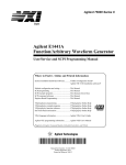
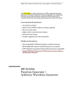
The five built-in arbitrary waveforms are shown below.
Sinc
Negative Ramp
Cardiac
Exponential Rise
Exponential Fall
175
Chapter 4 Remote Interface Reference
Arbitrary Waveform Commands
Arbitrary Waveform Commands
FUNCtion:USER {<arb name>|VOLATILE}
Select one of the five built-in arbitrary waveforms, one of four
user-defined waveforms, or the waveform currently downloaded to
VOLATILE memory.
The names of the five built-in arbitrary waveforms are:
“SINC”, “NEG_RAMP”, “EXP_RISE”, “EXP_FALL”, and “CARDIAC”.
To select the waveform currently stored in volatile memory, specify
the VOLATILE parameter. The keyword “VOLATILE” does not have a
short form. The correct syntax is: "FUNC:USER VOLATILE"
The FUNC:USER command does not output the selected waveform.
Use the FUNC:SHAP USER command to output the waveform.
If you select an arbitrary waveform name that is not currently
downloaded, a +785, “Specified arb waveform does not exist” error
is generated.
The arb name may contain up to 8 characters. The first character
must be a letter (A-Z), but the remaining characters can be
numbers (0-9) or the underscore character (“ _ ”). Blank spaces are
not allowed. If you specify a name with more than 8 characters,
a +783, “Arb waveform name too long” error is generated.
The function generator does not distinguish between upper- and
lower-case letters for the arbitrary waveform name. Therefore,
ARB_1 and arb_1 are the same name. All characters are converted
to upper case.
Use the DATA:CAT? command to list the names of the five built-in
waveforms (non-volatile), “VOLATILE” if a waveform is currently
downloaded to volatile memory, and the names of any user-defined
waveforms (non-volatile).
The following statement shows how to use the FUNC:USER command:
"FUNC:USER NEG_RAMP"
FUNCtion:USER?
Query the arbitrary waveform currently selected. Returns “SINC”,
“NEG_RAMP”, “EXP_RISE”, “EXP_FALL”, “CARDIAC”, “VOLATILE”,
or the name of any user-defined waveforms in non-volatile memory.
176
Chapter 4 Remote Interface Reference
Arbitrary Waveform Commands
FUNCtion:SHAPe USER
Select the function and output the selected arbitrary waveform. When
executed, this command outputs the arbitrary waveform currently selected
by the FUNC:USER command. The selected waveform is output using the
previously selected frequency, amplitude, and offset settings.
Use the FREQ, VOLT, and VOLT:OFFS commands to select the
frequency, amplitude, and offset of the waveform. Or, use the
APPLy command to select the function, frequency, amplitude, and
offset with a single command.
As shown in the following table, you can use the arbitrary waveform
function with all of the modulation modes. Each “X” indicates a valid
combination.
AM Carrier
AM Modulating Wave
FM Carrier
FM Modulating Wave
FSK Modulation
Burst Modulation
Frequency Sweep
Sine
Square
Triangle
Ramp
X
X
X
X
X
X
X
X
X
X
X
X
X
X
X
X
X
X
X
X
X
X
X
X
X
X
X
X
Noise
X
X
Arb
X
X
X
X
X
X
X
For arbitrary waveforms, the maximum amplitude will be limited if
the data points do not span the full range of the output DAC (Digitalto-Analog Converter). For example, the built-in “SINC” waveform does
not use the full range of values between 1 and therefore its
maximum amplitude is 6.084 Vpp (into 50 ohms).
For arbitrary waveforms, the Offset annunciator will turn on if the
waveform data has an inherent offset present (if the average is not
equal to zero). The function generator calculates the average of the
data points and compares the average to zero volts. If the average is
not within two DAC (Digital-to-Analog Converter) counts of zero volts,
the Offset annunciator turns on.
FUNCtion:SHAPe?
Query the output function. Returns “SIN”, “SQU”, “TRI”, “RAMP”, “NOIS”,
“DC”, or “USER”.
177
4
Chapter 4 Remote Interface Reference
Arbitrary Waveform Commands
DATA VOLATILE, <value>, <value>, . . .
Download floating-point values between -1 and +1 into volatile memory.
You can download between 8 and 16,000 points per waveform.
The values -1 and +1 correspond to the peak values of the waveform.
For example, if you set the amplitude to 10 Vpp, “-1” corresponds to
-5 volts and “+1” corresponds to +5 volts.
The maximum amplitude will be limited if the data points do not
span the full range of the output DAC (Digital-to-Analog Converter).
For example, the built-in “SINC” waveform does not use the full range
of values between 1 and therefore its maximum amplitude is
6.084 Vpp (into 50 ohms).
Downloading floating-point values (using DATA VOLATILE) is slower
than downloading binary values (using DATA:DAC VOLATILE) but is
more convenient when using trigonometric functions which return
values between -1 and +1.
The DATA VOLATILE command overwrites the previous waveform in
VOLATILE memory (no error is generated). Use the DATA:COPY
command to copy the waveform to non-volatile memory.
Up to four user-defined waveforms can be stored in non-volatile
memory. Use the DATA:DEL command to delete the waveform in
VOLATILE memory or any of the four user-defined waveforms in
non-volatile memory. Use the DATA:CAT? command to list all
waveforms currently stored in volatile and non-volatile memory
(and the built-in waveforms).
After downloading the waveform data to memory, use the FUNC:USER
command to choose the active waveform and the FUNC:SHAP USER
command to output it.
The following statement shows how to use the DATA VOLATILE
command to download nine points to volatile memory:
"DATA VOLATILE, 1,.75,.5,.25,0,-.25,-.5,-.75,-1"
178
Chapter 4 Remote Interface Reference
Arbitrary Waveform Commands
DATA:DAC VOLATILE, {<binary block>|<value>, <value>, . . . }
Download binary integer values between -2047 and +2047 into volatile
memory. You can download between 8 and 16,000 points per waveform
in IEEE-488.2 binary block format or as a list of values. The binary range
of values corresponds to the values available using internal 12-bit DAC
(Digital-to-Analog Converter) codes.
The values -2047 and +2047 correspond to the peak values of the
waveform. For example, if you have set the output amplitude to
10 Vpp, “-2047” corresponds to -5 volts and “+2047” corresponds to
+5 volts.
The maximum amplitude will be limited if the data points do not
span the full range of the output DAC (Digital-to-Analog Converter).
For example, the built-in “SINC” waveform does not use the full range
of values between 1 and therefore its maximum amplitude is
6.084 Vpp (into 50 ohms).
The DATA:DAC VOLATILE command overwrites the previous
waveform in VOLATILE memory (no error is generated). Use the
DATA:COPY command to copy the waveform to non-volatile memory.
Up to four user-defined waveforms can be stored in non-volatile
memory. Use the DATA:DEL command to delete the waveform in
VOLATILE memory or any of the four user-defined waveforms in
non-volatile memory. Use the DATA:CAT? command to list all
waveforms currently stored in volatile and non-volatile memory
(and the built-in waveforms).
After downloading the waveform data to memory, use the FUNC:USER
command to choose the active waveform and the FUNC:SHAP USER
command to output it.
179
4
Chapter 4 Remote Interface Reference
Arbitrary Waveform Commands
DATA:DAC VOLATILE
(continued)
To download binary data over the RS-232 interface, you must select
8 data bits with no parity. See “RS-232 Interface Configuration” on
page 195 for more information.
The following statement shows how to use the DATA:DAC VOLATILE
command to download eight integer points using the binary block
format (see also “Using the IEEE-488.2 Binary Block Format” below):
"DATA:DAC VOLATILE, #216
Binary Data
"
The following statement shows how to use the DATA:DAC VOLATILE
command to download eight integer points:
"DATA:DAC VOLATILE, 2047,1536,1024,512,0,-512,-1536,-2047"
Using the IEEE-488.2 Binary Block Format
In the binary block format, a block header precedes the waveform data.
The block header has the following format:
#
5
32000
Start of
Data Block
Even Number of Bytes to Follow
(32,000 bytes = 16,000 points)
Number of Digits
to Follow
The function generator represents binary data as 12-bit integers, which is sent
as two bytes. Therefore, the total number of bytes is always twice the number
of data points in the waveform (and must always be an even number ). For example,
32,000 bytes are required to download a waveform with 16,000 points.
Use the FORM:BORD command to select the byte order for binary transfers in
block mode. If you specify FORM:BORD NORM (default), the most-significant
byte (MSB) of each data point is sent first. If you specify FORM:BORD SWAP,
the least-significant byte (LSB) of each data point is sent first. Most PCs use
the “swapped” byte order.
180
Chapter 4 Remote Interface Reference
Arbitrary Waveform Commands
DATA:ATTRibute:AVERage? [<arb name>]
Query the arithmetic average of all data points for the specified
arbitrary waveform. The default arb name is the arbitrary waveform
currently active (selected with FUNC:USER command).
If you query a waveform that is not currently stored in memory,
a +785, “Specified arb waveform does not exist” error is generated.
DATA:ATTRibute:CFACtor? [<arb name>]
Query the crest factor of all data points for the specified arbitrary
waveform. Crest factor is the ratio of the peak value to the RMS value of
the waveform. The default arb name is the arbitrary waveform
currently active (selected with FUNC:USER command).
If you query a waveform that is not currently stored in memory,
a +785, “Specified arb waveform does not exist” error is generated.
DATA:ATTRibute:POINts? [<arb name>]
Query the number of points in the specified arbitrary waveform.
Returns a value between 8 and 16,000 points. The default arb name is
the arbitrary waveform currently active (selected with FUNC:USER
command).
If you query a waveform that is not currently stored in memory,
a +785, “Specified arb waveform does not exist” error is generated.
DATA:ATTRibute:PTPeak? [<arb name>]
Query the peak-to-peak value of all data points for the specified
arbitrary waveform. The default arb name is the arbitrary waveform
currently active (selected with FUNC:USER command).
This command returns a value between “0” and “+1.0”, with “+1.0”
indicating full amplitude available (100%).
The maximum peak-to-peak amplitude will be limited if the data
points do not span the full range of the output DAC (Digital-to-Analog
Converter). For example, the built-in “SINC” waveform does not use
the full range of values between 1 and therefore its maximum
peak-to-peak amplitude is 6.084 Vpp (into 50 ohms).
If you query a waveform that is not currently stored in memory,
a +785, “Specified arb waveform does not exist” error is generated.
181
4
Chapter 4 Remote Interface Reference
Arbitrary Waveform Commands
DATA:CATalog?
List the names of all waveforms currently downloaded to memory.
Returns the names of the five built-in waveforms (non-volatile memory),
“VOLATILE” if a waveform is currently downloaded to volatile memory,
and all user-defined waveforms downloaded to non-volatile memory.
A series of quoted strings separated with commas is returned:
"SINC","NEG_RAMP","EXP_RISE","EXP_FALL",
"CARDIAC","VOLATILE","ARB_1","ARB_2"
Use the DATA:DEL command to delete the waveform in VOLATILE
memory or any of the user-defined waveforms in non-volatile memory.
DATA:COPY <destination arb name> [,VOLATILE]
Copy the waveform from volatile memory to the specified name in
non-volatile memory. The source for the copy is always “VOLATILE”
(you cannot copy from any other name) and you cannot copy to
VOLATILE. The VOLATILE parameter is optional and can be omitted.
The arb name may contain up to 8 characters. The first character
must be a letter (A-Z), but the remaining characters can be
numbers (0-9) or the underscore character (“ _ ”). Blank spaces are
not allowed. If you specify a name with more than 8 characters,
a +783, “Arb waveform name too long” error is generated.
The following built-in waveform names are reserved and cannot be
used with the DATA:COPY command: SINC, NEG_RAMP, EXP_RISE,
EXP_FALL, and CARDIAC. If you specify one of the built-in waveforms,
a +782, “Cannot overwrite a built-in arb waveform” error is generated.
The function generator does not distinguish between upper- and
lower-case letters. Therefore, ARB_1 and arb_1 are the same name.
All characters are converted to upper case.
182
Chapter 4 Remote Interface Reference
Arbitrary Waveform Commands
If you copy to a waveform name that already exists, the previous
waveform is overwritten (no error is generated). However, you cannot
overwrite any of the five built-in waveforms.
Up to four user-defined waveforms can be stored in non-volatile
memory. If memory is full and you try to copy a new waveform to
non-volatile memory, a +781, “Not enough memory” error is
generated. Use the DATA:DEL command to delete the waveform in
VOLATILE memory or any of the four user-defined waveforms in
non-volatile memory. Use the DATA:CAT? command to list all
waveforms currently stored in volatile and non-volatile memory.
The following statement shows how to use the DATA:COPY command:
"DATA:COPY ARB_1, VOLATILE"
DATA:DELete <arb name>
Delete the specified arbitrary waveform from memory. You can delete
the waveform in volatile memory or any of the four user-defined
waveforms in non-volatile memory.
You cannot delete the arbitrary waveform that is currently being
output. If you attempt to delete the waveform being output, a
+787, “Cannot delete an active arb waveform” error is generated.
You cannot delete any of the five built-in arbitrary waveforms. If you
attempt to delete one of the built-in waveforms, a +786, “Cannot delete a
built-in arb waveform” error is generated.
Use the DATA:DEL:ALL command to delete the waveform in VOLATILE
memory and all user-defined non-volatile waveforms all at once.
If one of the waveforms is currently being output, a +787, “Cannot
delete an active arb waveform” error is generated. The active
waveform is not deleted but all of the other waveforms are deleted.
183
4
Chapter 4 Remote Interface Reference
Arbitrary Waveform Commands
DATA:DELete:ALL
Delete all user-defined arbitrary waveforms from memory. This command
deletes the waveform in VOLATILE memory and all user-defined
waveforms in non-volatile memory. The five built-in waveforms in
non-volatile memory are not deleted.
The colon before the ALL parameter is required.
DATA:DELete:ALL
If you insert a space instead of a colon, the function generator will
attempt to delete an arbitrary waveform with the name “ALL”. If no
such waveform is stored in memory, a +785, “Specified arb waveform
does not exist” error is generated.
You cannot delete the arbitrary waveform that is currently being
output. If you attempt to delete the waveform being output, a
+787, “Cannot delete an active arb waveform” error is generated.
You cannot delete any of the five built-in arbitrary waveforms. If you
attempt to delete one of the built-in waveforms, a +786, “Cannot delete a
built-in arb waveform” error is generated.
Use the DATA:DEL <arb name> command to delete stored waveforms
one at a time.
DATA:NVOLatile:CATalog?
List the names of all user-defined arbitrary waveforms currently
downloaded to non-volatile memory. Returns the names of up to four
waveforms in non-volatile memory.
A series of quoted strings separated with commas is returned
(see example below). If no user-defined waveforms are currently
downloaded to non-volatile memory, the command returns a null
string ( "" ).
"ARB_1","ARB_2","ARB_3","ARB_4"
Use the DATA:DEL command to delete the waveform in VOLATILE
memory or any of the user-defined waveforms in non-volatile memory.
184
Chapter 4 Remote Interface Reference
Arbitrary Waveform Commands
DATA:NVOLatile:FREE?
Query the number of non-volatile memory slots available to store
user-defined waveforms. Non-volatile waveform memory is divided into
four 16k-point slots. This command returns the number of memory slots
available to store user-defined waveforms: “0” (memory is full), “1”, “2”,
“3”, or “4”.
FORMat:BORDer {NORMal|SWAPped}
Used only for binary block transfers. Select the byte order for binary
transfers in the block mode using the DATA:DAC command. The default
is NORM.
In NORM byte order (default), the most-significant byte (MSB) of
each data point is sent first.
In SWAP byte order, the least-significant byte (LSB) of each data
point is sent first. Most PCs use the “swapped” byte order.
The function generator represents binary data as 12-bit integers,
which are sent as two bytes. Each data point in the waveform
requires 12 bits, which must be transferred as 16 bits (two bytes) on
the function generator’s 8-bit interface.
FORMat:BORDer?
Query the byte order configuration. Returns “NORM” or “SWAP”.
185
4
Chapter 4 Remote Interface Reference
Triggering
Triggering
See also “Triggering,” starting on page 98 in chapter 3.
First-time
SCPI users,
see page 211.
Applies only to burst modulation and frequency sweep. You can issue
triggers for bursts and sweeps using an immediate trigger, an external
trigger, or a bus trigger.
TRIGger:SOURce {IMMediate|EXTernal|BUS}
Select the source from which the function generator will accept a
trigger. The function generator will accept an immediate internal
trigger, a hardware trigger from the rear-panel Ext Trig terminal,
or a software (bus) trigger. The default is Immediate.
[ Stored in volatile memory ]
When the Immediate (internal) source is selected, the function
generator outputs continuously when the burst mode or sweep mode
is enabled. The APPLy command automatically sets the trigger source
to IMMediate.
When the External source is selected, the function generator will
accept a hardware trigger applied to the rear-panel Ext Trig terminal.
The function generator outputs one burst or initiates one sweep each
time each time Ext Trig receives the rising edge of a TTL pulse.
The Trig annunciator turns on when the function generator is waiting
for an external trigger.
When the Bus (software) source is selected, the function generator
outputs one burst or initiates one sweep each time a bus trigger
command is received. To trigger the function generator from the
remote interface (GPIB or RS-232), send the *TRG (trigger) command.
You can also trigger the function generator from the GPIB interface by
sending the IEEE-488 Group Execute Trigger (GET) message
(e.g., TRIGGER 710).
186
Chapter 4 Remote Interface Reference
Triggering
To ensure synchronization when the Bus source is selected, send the
*WAI (wait) command. When the *WAI command is executed, the
function generator waits for all pending operations to complete before
executing any additional commands. For example, the following
command string guarantees that the first trigger is accepted and
executed before the second trigger is recognized.
"TRIG:SOUR BUS;*TRG;*WAI;*TRG;*WAI"
You can use the *OPC? (operation complete query) command or the
*OPC (operation complete) command to signal when the burst or
sweep is complete. The *OPC? command returns “1” to the output
buffer when the burst or sweep is complete. The *OPC command sets
the “operation complete” bit (bit 0) in the Standard Event register
when the burst or sweep is complete.
TRIGger:SOURce?
Query the present trigger source. Returns “IMM”, “EXT”, or “BUS”.
4
TRIGger:SLOPe {POSitive|NEGative}
Select the polarity of the Ext Trig terminal. If you select “POS”, the
polarity of the Ext Trig terminal is the same as described on page 102.
If you select “NEG”, the polarity is the opposite of what is described.
The default is Positive. [ Stored in volatile memory ]
TRIGger:SLOPe?
Query the present polarity of the Ext Trig terminal. Returns “POS” or “NEG”.
*TRG
Trigger the function generator from the remote interface. For RS-232
operation, make sure the interface is in the remote mode by sending the
SYST:REM command.
187
Chapter 4 Remote Interface Reference
System-Related Commands
System-Related Commands
See also “System-Related Operations,” starting on page 109 in chapter 3.
DISPlay {OFF|ON}
Turn the front-panel display off or on. When the display is turned off,
output parameters are not sent to the display and all annunciators
except ERROR and Shift are disabled. Front-panel operation is otherwise
unaffected by turning off the display. [ Stored in volatile memory ]
Sending a message to the display from the remote interface overrides
the display state; this means that you can display a message even if
the display is turned off.
The display state is automatically turned on when you return to the
local (front panel) state. Press the Shift key or execute LOCAL 710
from the remote interface to return to the local state.
DISPlay?
Query the front-panel display setting. Returns “0” (OFF) or “1” (ON).
DISPlay:TEXT <quoted string>
Display a message containing up to 11 characters on the front panel;
any additional characters are truncated. Commas, periods, and
semicolons share a display space with the preceding character, and are
not considered individual characters. When a message is displayed,
information relating to the output waveform (such as frequency and
amplitude) is not sent to the display. [ Stored in volatile memory ]
The DISP:TEXT command is allowed only while the function generator
is in the remote mode. An error is generated if you attempt to execute the
command while in the local mode.
The following command string shows how to display a message on the
front panel.
"DISP:TEXT ’HELLO’"
188
Chapter 4 Remote Interface Reference
System-Related Commands
DISPlay:TEXT?
Query the message sent to the front panel and return a quoted string.
For example, the query returns a string such as "HELLO".
DISPlay:TEXT:CLEar
Clear the message displayed on the front panel.
SYSTem:BEEPer
Issue a single beep immediately.
SYSTem:ERRor?
Read one error from the error queue. When the front-panel ERROR
annunciator turns on, one or more command syntax or hardware errors
have been detected. A record of up to 20 errors can be stored in the
function generator’s error queue. See chapter 5, “Error Messages,” for a
complete listing of the errors.
Errors are retrieved in first-in-first-out (FIFO) order. The first error
returned is the first error that was stored. When you have read all
errors from the queue, the ERROR annunciator turns off. The function
generator beeps once each time an error is generated.
If more than 20 errors have occurred, the last error stored in the
queue (the most recent error) is replaced with -350, “Too many errors”.
No additional errors are stored until you remove errors from the
queue. If no errors have occurred when you read the error queue,
the function generator responds with +0, “No error”.
The error queue is cleared when power has been off or after a *CLS
(clear status) command has been executed. The *RST (reset)
command does not clear the error queue.
Errors have the following format (the error string may contain
up to 80 characters):
-113,"Undefined header"
189
4
Chapter 4 Remote Interface Reference
System-Related Commands
SYSTem:VERSion?
Query the function generator to determine the present SCPI version.
Returns a string in the form “YYYY.V” where the “Y’s” represent the
year of the version, and the “V” represents a version number for that
year (for example, 1993.0).
*IDN?
Read the function generator’s identification string. The function
generator returns four fields separated by commas. The first field is the
manufacturer’s name, the second field is the model number, the third
field is not used (always “0”), and the fourth field is a revision code
which contains three numbers. The first number is the firmware
revision number for the main generator processor; the second is for the
input/output processor; and the third is for the front-panel processor.
The command returns a string with the following format (be sure to
dimension a string variable with at least 40 characters):
HEWLETT-PACKARD,33120A,0,X.X-X.X-X.X
*RST
Reset the function generator to its default state (see “Power-On and
Reset State” on page 123) independent of the POWER ON command
setting in the front-panel SYS MENU.
In the sweep mode, the *RST command does not set the start and stop
frequencies to their default values. Instead, the reset operation sets the
start frequency to 10 mHz (minimum) and the stop frequency to 15 MHz
(maximum).
*TST?
Perform a complete self-test of the function generator. Returns “+0” if
the self-test passes or “+1” if it fails. If the self-test fails, an error
message is also generated with additional information on why the test
failed.
190
Chapter 4 Remote Interface Reference
System-Related Commands
*SAV {0|1|2|3}
Store up to four different instrument configurations.
[ Stored in non-volatile memory ]
Four memory locations (numbered 0, 1, 2, and 3) are available to store
instrument configurations. The state storage feature “remembers” the
function (including arbitrary waveforms), frequency, amplitude,
dc offset, duty cycle, as well as any modulation parameters. To recall
a stored state, you must use the same memory location used
previously to store the state.
From the remote interface only, you can use memory location “0” to
store a fourth instrument configuration (you cannot store to this
memory location from the front panel). However, keep in mind that
memory location “0” is automatically overwritten when the power is
turned off.
Any arbitrary waveforms downloaded to “VOLATILE” memory are not
remembered. However, if an arbitrary waveform is being output
from non-volatile memory when the state is stored, the waveform
data is stored. The stored waveform is output when the instrument
state is recalled.
If you delete an arbitrary waveform after storing the state, the
waveform data is lost and the function generator will not output the
waveform when the state is recalled. The “SINC” waveform is output
in place of the deleted waveform.
When power is turned off, the function generator automatically stores
its state in memory location “0”. You can configure the function
generator to automatically recall the power-down state when power is
restored. The recall mode is disabled when the function generator is
shipped from the factory.
Select the POWER ON LAST STATE command from the SYS MENU to
enable the power-down recall mode. Select POWER ON DEFAULT to
disable the power-down recall mode. See “Power-Down Recall Mode”
on page 109 for more information.
191
4
Chapter 4 Remote Interface Reference
System-Related Commands
*RCL {0|1|2|3}
Recall a previously stored state. To recall a stored state, you must use
the same memory location used previously to store the state.
You cannot recall the instrument state from a memory location that
was not previously specified as a storage location. For example, an
error is generated if you attempt to recall from memory location “2”
but have never stored to that location. From the remote interface, a
+810, “State has not been stored” error is generated if nothing is stored
in the specified memory location.
MEMory:STATe:DELete {0|1|2|3}
Delete a previously stored state and clear the memory location.
If nothing is stored in the specified memory location, a +810, “State has
not been stored” error is generated.
*OPC
Set the “operation complete” bit (bit 0) in the Standard Event register
after the previous commands have been executed. Used only in the
triggered burst mode and triggered sweep mode.
*OPC?
Return “1” to the output buffer after the previous commands have
been executed. Used only in the triggered burst mode and triggered
sweep mode.
*WAI
Wait for all pending operations to complete before executing any
additional commands over the interface. Used only in the triggered burst
mode and triggered sweep mode.
192
Chapter 4 Remote Interface Reference
Calibration Commands
Calibration Commands
See “Calibration Overview” starting on page 118 for an overview of the
calibration features of the function generator. For a more detailed
discussion of the calibration procedures, see chapter 4 in the Service Guide.
CALibration?
Perform a calibration using the specified calibration value
(CAL:VAL command). Before you can calibrate the function generator,
you must unsecure it by entering the correct security code.
CALibration:COUNt?
Query the function generator to determine the number of times it has
been calibrated. Your function generator was calibrated before it left the
factory. When you receive your function generator, read the count to
determine its initial value. [ Stored in non-volatile memory ]
The calibration count increments up to a maximum of 32,767 after
which it wraps-around to 0. Since the value increments by one for
each calibration point, a complete calibration will increase the value
by many counts.
CALibration:SECure:CODE <new code>
Enter a new security code. To change the security code, you must first
unsecure the function generator using the old security code, and then
enter a new code. The calibration code may contain up to 12 characters.
[ Stored in non-volatile memory ]
CALibration:SECure:STATe {OFF|ON},<code>
Unsecure or secure the function generator for calibration. The calibration
code may contain up to 12 characters. [ Stored in non-volatile memory ]
CALibration:SECure:STATe?
Query the secured state of the function generator. Returns “0” (OFF)
or “1” (ON).
193
4
Chapter 4 Remote Interface Reference
Calibration Commands
CALibration:SETup <0|1|2|3| . . . |84>
Configure the function generator’s internal state for each of the
calibration steps to be performed.
CALibration:SETup?
Query the calibration setup number. Returns a value between 0 and 84.
CALibration:STRing <quoted string>
Record calibration information about your function generator.
For example, you can store such information as the last calibration
date, the next calibration due date, the instrument serial number,
or even the name and phone number of the person to contact for a new
calibration. [ Stored in non-volatile memory ]
You can record information in the calibration message only from the
remote interface. However, you can read the message from either the
front-panel menu or the remote interface.
The calibration message may contain up to 40 characters. However,
the function generator can display only 11 characters of the message
on the front panel (additional characters are truncated).
CALibration:STRing?
Query the calibration message and return a quoted string.
CALibration:VALue <value>
Specify the value of the known calibration signal used by the calibration
procedure. Use the CAL:SET command to configure the function
generator’s internal state for each of the calibration steps to be performed.
CALibration:VALue?
Query the present calibration value.
194
Chapter 4 Remote Interface Reference
RS-232 Interface Configuration
RS-232 Interface Configuration
See also “Remote Interface Configuration,” on page 114 in chapter 3.
You connect the function generator to the RS-232 interface using the
9-pin (DB-9) serial connector on the rear panel. The function generator
is configured as a DTE (Data Terminal Equipment) device. For all
communications over the RS-232 interface, the function generator
uses two handshake lines: DTR (Data Terminal Ready) on pin 4 and
DSR (Data Set Ready) on pin 6.
The following sections contain information to help you use the function
generator over the RS-232 interface. The programming commands for
RS-232 are listed on page 200.
RS-232 Configuration Overview
Configure the RS-232 interface using the parameters shown below.
Use the front-panel I/O MENU to select the baud rate, parity, and
number of data bits (see also pages 219 and 220 for more information).
Baud Rate: 300, 600, 1200, 2400, 4800, or 9600 baud (factory setting)
Parity and Data Bits:
None / 8 data bits (factory setting)
Even / 7 data bits, or
Odd / 7 data bits
Number of Start Bits: 1 bit (fixed)
Number of Stop Bits:
2 bits (fixed)
To download binary data for arbitrary waveforms over the RS-232
interface, you must select 8 data bits with no parity.
195
4
Chapter 4 Remote Interface Reference
RS-232 Interface Configuration
RS-232 Data Frame Format
A character frame consists of all the transmitted bits that make up a
single character. The frame is defined as the characters from the start bit
to the last stop bit, inclusively. Within the frame, you can select the
baud rate, number of data bits, and parity type. The function generator
uses the following frame formats for seven and eight data bits.
Connection to a Computer or Terminal
To connect the function generator to a computer or terminal, you must
have the proper interface cable. Most computers and terminals are DTE
(Data Terminal Equipment) devices. Since the function generator is also
a DTE device, you must use a DTE-to-DTE interface cable. These cables
are also called null-modem, modem-eliminator, or crossover cables.
The interface cable must also have the proper connector on each end
and the internal wiring must be correct. Connectors typically have
9 pins (DB-9 connector) or 25 pins (DB-25 connector) with a “male”
or “female” pin configuration. A male connector has pins inside the
connector shell and a female connector has holes inside the connector shell.
If you cannot find the correct cable for your configuration, you may
have to use a wiring adapter. If you are using a DTE-to-DTE cable, make
sure the adapter is a “straight-through” type. Typical adapters include
gender changers, null-modem adapters, and DB-9 to DB-25 adapters.
Refer to the cable and adapter diagrams on the following page to
connect the function generator to most computers or terminals. If your
configuration is different than those described, order the 34399A
Adapter Kit. This kit contains adapters for connection to other
computers, terminals, and modems. Instructions and pin diagrams are
included with the adapter kit.
196
Chapter 4 Remote Interface Reference
RS-232 Interface Configuration
DB-9 Serial Connection If your computer or terminal has a 9-pin
serial port with a male connector, use the null-modem cable included
with the 34398A Cable Kit. This cable has a 9-pin female connector on
each end. The cable pin diagram is shown below.
4
DB-25 Serial Connection If your computer or terminal has a 25-pin
serial port with a male connector, use the null-modem cable and 25-pin
adapter included with the 34398A Cable Kit. The cable and adapter pin
diagram is shown below.
197
Chapter 4 Remote Interface Reference
RS-232 Interface Configuration
DTR / DSR Handshake Protocol
The function generator is configured as a DTE (Data Terminal Equipment)
device and uses the DTR (Data Terminal Ready) and DSR (Data Set Ready)
lines of the RS-232 interface to handshake. The function generator uses
the DTR line to send a hold-off signal. The DTR line must be TRUE
before the function generator will accept data from the interface. When
the function generator sets the DTR line FALSE, the data must cease
within 10 characters.
To disable the DTR/DSR handshake, do not connect the DTR line and tie
the DSR line to logic TRUE. If you disable the DTR/DSR handshake, also
select a slower baud rate (300, 600, or 1200 baud) to ensure that the
data is transmitted correctly.
The function generator sets the DTR line FALSE in the following cases:
1 When the function generator’s input buffer is full (when approximately
100 characters have been received), it sets the DTR line FALSE (pin 4 on
the RS-232 connector). When enough characters have been removed to
make space in the input buffer, the function generator sets the DTR line
TRUE, unless the second case (see below) prevents this.
2 When the function generator wants to “talk” over the interface (which
means that it has processed a query) and has received a <new line>
message terminator, it will set the DTR line FALSE. This implies that
once a query has been sent to the function generator, the controller
should read the response before attempting to send more data. It also
means that a <new line> must terminate the command string. After the
response has been output, the function generator sets the DTR line
TRUE again, unless the first case (see above) prevents this.
The function generator monitors the DSR line to determine when the
controller is ready to accept data over the interface. The function
generator monitors the DSR line (pin 6 on the RS-232 connector) before
each character is sent. The output is suspended if the DSR line is
FALSE. When the DSR line goes TRUE, transmission will resume.
198
Chapter 4 Remote Interface Reference
RS-232 Interface Configuration
The function generator holds the DTR line FALSE while output is
suspended. A form of interface deadlock exists until the controller
asserts the DSR line TRUE to allow the function generator to complete
the transmission. You can break the interface deadlock by sending the
<Ctrl-C> character, which clears the operation in progress and discards
pending output (this is equivalent to the IEEE-488 device clear action).
For the <Ctrl-C> character to be recognized reliably by the function
generator while it holds DTR FALSE, the controller must first set DSR
FALSE. When downloading binary data for an arbitrary waveform,
press the front-panel LOCAL key first and then send <Ctrl-C>.
RS-232 Troubleshooting
Here are a few things to check if you are having problems communicating
over the RS-232 interface. If you need additional help, refer to the
documentation that came with your computer.
Verify that the function generator and your computer are configured
for the same baud rate, parity, and number of data bits. Make sure
that your computer is set up for 1 start bit and 2 stop bits (these values
are fixed on the function generator).
Make sure to execute the SYSTEM:REMOTE command to place the
function generator in the REMOTE mode.
Verify that you have connected the correct interface cable and adapters.
Even if the cable has the proper connectors for your system, the
internal wiring may not be correct. The 34398A Cable Kit can be used
to connect the function generator to most computers or terminals.
Verify that you have connected the interface cable to the correct
serial port on your computer (COM1, COM2, etc).
199
4
Chapter 4 Remote Interface Reference
RS-232 Interface Commands
RS-232 Interface Commands
Use the front-panel I/O MENU to select the baud rate, parity, and
number of data bits (see pages 219 and 220 for more information).
SYSTem:LOCal
Place the function generator in the local mode for RS-232 operation.
All keys on the front panel are fully functional.
SYSTem:REMote
Place the function generator in the remote mode for RS-232 operation.
All keys on the front panel, except the LOCAL key, are disabled.
It is very important that you send the SYSTEM:REMOTE command
to place the function generator in the remote mode. Sending or receiving
data over the RS-232 interface when not configured for remote operation
can cause unpredictable results.
SYSTem:RWLock
Place the function generator in the remote mode for RS-232 operation.
This command is the same as the SYSTEM:REMOTE command except
that all keys on the front panel are disabled, including the LOCAL key.
Ctrl-C
Clear the operation in progress over the RS-232 interface and discard
any pending output data. This is equivalent to the IEEE-488 device clear
action over the GPIB interface.
200
Chapter 4 Remote Interface Reference
The SCPI Status Registers
The SCPI Status Registers
The function generator uses the Status Byte register group and the
Standard Event register group to record various instrument conditions.
A diagram of the SCPI status system is shown on the next page.
An example program is included in chapter 6, “Application Programs,”
which shows the use of the status registers. You may find it useful to
refer to the program after reading the following section in this chapter.
What is an Event Register?
An event register is a read-only register that reports defined conditions
within the function generator. Bits in an event register are latched.
When an event bit is set, subsequent state changes are ignored. Bits in
an event register are automatically cleared by a query of that register
or by sending the *CLS (clear status) command. The *RST (reset)
command or device clear will not clear bits in an event register.
Querying an event register returns a decimal value which corresponds
to the binary-weighted sum of all bits set in the register.
What is an Enable Register?
An enable register defines which bits in the corresponding event register
are logically ORed together to form a single summary bit. You can read
from, and write, to an enable register. Querying an enable register will not
clear it. The *CLS (clear status) command does not clear enable
registers but it does clear the bits in the event registers. To enable bits
in an enable register, you must write a decimal value which corresponds
to the binary-weighted sum of the bits you wish to enable in the register.
201
4
Chapter 4 Remote Interface Reference
The SCPI Status Registers
SCPI Status System
202
Chapter 4 Remote Interface Reference
The SCPI Status Registers
The Status Byte Register
The Status Byte summary register reports conditions from the other
status registers. Query data that is waiting in the function generator’s
output buffer is immediately reported through the “message available”
bit (bit 4). Bits in the summary register are not latched. Clearing an
event register will clear the corresponding bits in the Status Byte
summary register. Reading all messages in the output buffer, including
any pending queries, will clear the message available bit.
Bit Definitions – Status Byte Register
Bit
0
1
2
3
4
5
Not Used
Not Used
Not Used
Not Used
Message Available
Standard Event
6 Request Service
7 Not Used
Decimal
Value
1
2
4
8
16
32
64
128
Definition
Always set to 0.
Always set to 0.
Always set to 0.
Always set to 0.
Data is available in the output buffer.
One or more bits are set in the Standard Event
register (bits must be “enabled” in enable register).
Requesting service (serial poll).
Always set to 0.
The Status Byte Summary Register is cleared when:
You execute the *CLS (clear status) command.
Querying the Standard Event register (*ESR? command) will clear
only bit 4 in the Summary Register.
The Status Byte Enable Register (request service) is cleared when:
You execute the *SRE 0 command.
You turn on the power and have previously configured the function
generator using the *PSC 1 command.
The enable register will not be cleared at power-on if you have
previously configured the function generator using *PSC 0.
203
4
Chapter 4 Remote Interface Reference
The SCPI Status Registers
Using Service Request (SRQ) and Serial POLL
You must configure your bus controller to respond to the IEEE-488
service request (SRQ) interrupt to use this capability. Use the Status
Byte enable register (*SRE command) to select which summary bits will
set the low-level IEEE-488 service request signal. When bit 6 (request
service) is set in the Status Byte, an IEEE-488 service request interrupt
message is automatically sent to the bus controller. The bus controller
may then poll the instruments on the bus to identify which one
requested service (the instrument with bit 6 set in its Status Byte).
The request service bit is cleared only by reading the Status Byte using
an IEEE-488 serial poll or by reading the event register whose summary
bit is causing the service request.
To read the Status Byte summary register, send the IEEE-488 serial poll
message. Querying the summary register will return a decimal value
which corresponds to the binary-weighted sum of the bits set in the
register. Serial poll will automatically clear the “request service” bit in
the Status Byte summary register. No other bits are affected.
Performing a serial poll will not affect instrument throughput.
Caution
The IEEE-488.2 standard does not ensure synchronization between your
bus controller program and the instrument. Use the *OPC? command to
guarantee that commands previously sent to the instrument have
completed. Executing a serial poll before a *RST, *CLS, or other
commands have completed can cause previous conditions to be reported.
204
Chapter 4 Remote Interface Reference
The SCPI Status Registers
Using *STB? to Read the Status Byte
The *STB? (status byte query) command is similar to a serial poll but it
is processed like any other instrument command. The *STB? command
returns the same result as a serial poll but the “request service” bit
(bit 6) is not cleared if a serial poll has occurred.
The *STB? command is not handled automatically by the IEEE-488 bus
interface hardware and will be executed only after previous commands
have completed. Polling is not possible using the *STB? command.
Executing the *STB? command does not clear the Status Byte summary
register.
Using the Message Available Bit (MAV)
You can use the Status Byte “message available” bit (bit 4) to determine
when data is available to read into your bus controller. The function
generator subsequently clears bit 4 only after all messages have been read
from the output buffer.
To Interrupt Your Bus Controller Using SRQ
1 Send a device clear message to clear the function generator’s
output buffer (e.g., CLEAR 710).
2 Clear the event registers with the *CLS (clear status) command.
3 Set up the enable register masks. Execute the *ESE command to set up
the Standard Event register and the *SRE command for the Status Byte.
4 Send the *OPC? (operation complete query) command and enter the
result to ensure synchronization.
5 Enable your bus controller’s IEEE-488 SRQ interrupt.
205
4
Chapter 4 Remote Interface Reference
The SCPI Status Registers
To Determine When a Command Sequence is Completed
1 Send a device clear message to clear the function generator’s
output buffer (e.g., CLEAR 710).
2 Clear the event registers with the *CLS (clear status) command.
3 Enable the “operation complete” bit (bit 0) in the Standard Event
register by executing the *ESE 1 command.
4 Send the *OPC? (operation complete query) command and enter the
result to ensure synchronization.
5 Execute your command string to program the desired configuration,
and then execute the *OPC (operation complete) command as the last
command. When the command sequence is completed, the “operation
complete” bit (bit 0) is set in the Standard Event register.
6 Use a serial poll to check to see when bit 5 (standard event) is set in the
Status Byte summary register. You could also configure the function
generator for an SRQ interrupt by sending *SRE 32 (Status Byte enable
register, bit 5).
206
Chapter 4 Remote Interface Reference
The SCPI Status Registers
The Standard Event Register
The Standard Event register reports the following types of instrument
events: power-on detected, command syntax errors, command execution
errors, self-test or calibration errors, query errors, or when an *OPC
command is executed. Any or all of these conditions can be reported in
the Standard Event summary bit through the enable register. To set the
enable register mask, you write a decimal value to the register using the
*ESE (event status enable) command.
An error condition (Standard Event register bits 2, 3, 4, or 5) will always
record one or more errors in the function generator’s error queue.
Read the error queue using the SYSTem:ERRor? command.
4
Bit Definitions – Standard Event Register
Bit
Decimal
Value
0 Operation Complete
1
1 Not Used
2 Query Error
2
4
3 Device Error
8
4 Execution Error
16
5 Command Error
32
6 Not Used
7 Power On
64
128
Definition
All commands prior to and including an *OPC
command have been executed.
Always set to 0.
The function generator tried to read the output buffer
but it was empty. Or, a new command line was
received before a previous query has been read.
Or, both the input and output buffers are full.
A self-test or calibration error occurred (see error
numbers 501 through 857 in chapter 5).
An execution error occurred (see error numbers
-211 through -224 in chapter 5).
A command syntax error occurred (see errors
-101 through -168 in chapter 5).
Always set to 0.
Power has been turned off and on since the last
time the event register was read or cleared.
207
Chapter 4 Remote Interface Reference
The SCPI Status Registers
The Standard Event register is cleared when:
You execute the *CLS (clear status) command.
You query the event register using the *ESR? (event status register)
command.
The Standard Event enable register is cleared when:
You execute the *ESE 0 command.
You turn on the power and have previously configured the function
generator using the *PSC 1 command.
The enable register will not be cleared at power-on if you have
previously configured the function generator using *PSC 0.
208
Chapter 4 Remote Interface Reference
Status Reporting Commands
Status Reporting Commands
SYSTem:ERRor?
Read one error from the error queue. When the front-panel ERROR
annunciator turns on, one or more command syntax or hardware errors
have been detected. A record of up to 20 errors can be stored in the
function generator’s error queue. See chapter 5, “Error Messages,” for a
complete listing of the errors.
Errors are retrieved in first-in-first-out (FIFO) order. The first error
returned is the first error that was stored. When you have read all
errors from the queue, the ERROR annunciator turns off. The function
generator beeps once each time an error is generated.
If more than 20 errors have occurred, the last error stored in the
queue (the most recent error) is replaced with -350, “Too many errors”.
No additional errors are stored until you remove errors from the
queue. If no errors have occurred when you read the error queue,
the function generator responds with +0, “No error”.
The error queue is cleared when power has been off or after a *CLS
(clear status) command has been executed. The *RST (reset)
command does not clear the error queue.
*CLS
Clear the Status Byte summary register and all event registers.
*ESE <enable value>
Enable bits in the Standard Event enable register. The selected bits are
then reported to the Status Byte.
*ESE?
Query the Standard Event enable register. The function generator
returns a decimal value which corresponds to the binary-weighted sum
of all bits set in the register.
*ESR?
Query the Standard event register. The function generator returns a
decimal value which corresponds to the binary-weighted sum of all bits
set in the register.
209
4
Chapter 4 Remote Interface Reference
Status Reporting Commands
*OPC
Set the “operation complete” bit (bit 0) in the Standard Event register
after the previous commands have been executed. Used only in the
triggered burst mode and triggered sweep mode.
*OPC?
Return “1” to the output buffer after the previous commands have
been executed. Used only in the triggered burst mode and triggered
sweep mode.
*PSC {0|1}
Power-on status clear. Clear the Status Byte and Standard Event
register enable masks when power is turned on (*PSC 1). When
*PSC 0 is in effect, the Status Byte and Standard Event register enable
masks are not cleared when power is turned on. The factory setting is
“1” (enabled). [ Stored in non-volatile memory ]
*PSC?
Query the power-on status clear setting. Returns “0” (*PSC 0) or “1”
(*PSC 1).
*SRE <enable value>
Enable bits in the Status Byte enable register.
*SRE?
Query the Status Byte enable register. The function generator returns
a decimal value which corresponds to the binary-weighted sum of all
bits set in the register.
*STB?
Query the Status Byte summary register. The *STB? command is
similar to a serial poll but it is processed like any other instrument
command. The *STB? command returns the same result as a serial poll
but the “request service” bit (bit 6) is not cleared if a serial poll has
occurred.
*WAI
Wait for all pending operations to complete before executing any
additional commands over the interface. Used only in the triggered burst
mode and triggered sweep mode.
210
Chapter 4 Remote Interface Reference
An Introduction to the SCPI Language
An Introduction to the SCPI Language
SCPI (Standard Commands for Programmable Instruments) is an
ASCII-based instrument command language designed for test and
measurement instruments. Refer to “Simplified Programming Overview,”
starting on page 136, for an introduction to the basic techniques used to
program the function generator over the remote interface.
SCPI commands are based on a hierarchical structure, also known as a
tree system. In this system, associated commands are grouped together
under a common node or root, thus forming subsystems. A portion of the
SOURCE subsystem is shown below to illustrate the tree system.
SOURce:
FREQuency:
STARt {<frequency>|MINimum|MAXimum}
FREQuency:
STARt? [MINimum|MAXimum]
FREQuency:
STOP {<frequency>|MINimum|MAXimum}
FREQuency:
STOP? [MINimum|MAXimum]
4
SWEep:
SPACing {LINear|LOGarithmic}
SWEep:
SPACing?
SWEep:
TIME {<seconds>|MINimum|MAXimum}
SWEep:
TIME? [MINimum|MAXimum]
SWEep:
STATe {OFF|ON}
SWEep:
STATe?
SOURce is the root keyword of the command, FREQuency and SWEep are
second-level keywords, and STARt and STOP are third-level keywords.
A colon ( : ) separates a command keyword from a lower-level keyword.
211
Chapter 4 Remote Interface Reference
An Introduction to the SCPI Language
Command Format Used in This Manual
The format used to show commands in this manual is shown below:
FREQuency {<frequency>|MINimum|MAXimum}
The command syntax shows most commands (and some parameters)
as a mixture of upper- and lower-case letters. The upper-case letters
indicate the abbreviated spelling for the command. For shorter program
lines, send the abbreviated form. For better program readability, send
the long form.
For example, in the above syntax statement, FREQ and FREQUENCY
are both acceptable forms. You can use upper- or lower-case letters.
Therefore, FREQUENCY, freq, and Freq are all acceptable. Other forms,
such as FRE and FREQUEN, will generate an error.
Braces ( { } ) enclose the parameter choices for a given command string.
The braces are not sent with the command string.
A vertical bar ( | ) separates multiple parameter choices for a given
command string.
Triangle brackets ( < > ) indicate that you must specify a value for the
enclosed parameter. For example, the above syntax statement shows
the frequency parameter enclosed in triangle brackets. The brackets are
not sent with the command string. You must specify a value for the
parameter (such as "FREQ 5000").
Some parameters are enclosed in square brackets ( [ ] ). The brackets
indicate that the parameter is optional and can be omitted. The brackets
are not sent with the command string. If you do not specify a value for
an optional parameter, the function generator chooses a default value.
212
Chapter 4 Remote Interface Reference
An Introduction to the SCPI Language
Command Separators
A colon ( : ) is used to separate a command keyword from a lower-level
keyword. You must insert a blank space to separate a parameter from a
command keyword. If a command requires more than one parameter,
you must separate adjacent parameters using a comma as shown below:
"APPL:SIN
5 KHZ, 3.0 VPP, -2.5 V"
A semicolon ( ; ) is used to separate commands within the same
subsystem, and can also minimize typing. For example, sending the
following command string:
"FREQ:START 10; STOP 1000; MODE SWEEP"
... is the same as sending the following three commands:
"FREQ:START 10"
"FREQ:STOP 1000"
"FREQ:MODE SWEEP"
4
Use a colon and a semicolon to link commands from different subsystems.
For example, in the following command string, an error is generated if
you do not use both the colon and semicolon:
"SWE:STAT ON;:TRIG:SOUR EXT"
Using the MIN and MAX Parameters
You can substitute MINimum or MAXimum in place of a parameter for
many commands. For example, consider the following command:
FREQuency {<frequency>|MINimum|MAXimum}
Instead of selecting a specific frequency, you can substitute MIN to set
the frequency to its minimum value or MAX to set the frequency to its
maximum value.
213
Chapter 4 Remote Interface Reference
An Introduction to the SCPI Language
Querying Parameter Settings
You can query the current value of most parameters by adding a
question mark ( ? ) to the command. For example, the following
command sets the output frequency to 5 kHz:
"FREQ 5000"
You can query the frequency value by executing:
"FREQ?"
You can also query the minimum or maximum frequency allowed with
the present function as follows:
"FREQ? MIN"
"FREQ? MAX"
SCPI Command Terminators
A command string sent to the function generator must terminate with
a <new line> character. The IEEE-488 EOI (end-or-identify) message is
interpreted as a <new line> character and can be used to terminate a
command string in place of a <new line> character. A <carriage return>
followed by a <new line> is also accepted. Command string termination
will always reset the current SCPI command path to the root level.
IEEE-488.2 Common Commands
The IEEE-488.2 standard defines a set of common commands that
perform functions like reset, self-test, and status operations. Common
commands always begin with an asterisk ( * ), are four to five characters
in length, and may include one or more parameters. The command
keyword is separated from the first parameter by a blank space. Use a
semicolon ( ; ) to separate multiple commands as shown below:
"*RST; *CLS; *ESE 32; *OPC?"
214
Chapter 4 Remote Interface Reference
An Introduction to the SCPI Language
SCPI Parameter Types
The SCPI language defines several different data formats to be used in
program messages and response messages.
Numeric Parameters Commands that require numeric parameters
will accept all commonly used decimal representations of numbers
including optional signs, decimal points, and scientific notation. Special
values for numeric parameters like MINimum, MAXimum, and DEFault
are also accepted. You can also send engineering unit suffixes with
numeric parameters (e.g., Mhz or Khz). If only specific numeric values
are accepted, the function generator will automatically round the input
numeric parameters. The following command uses a numeric parameter:
FREQuency {<frequency>|MINimum|MAXimum}
Discrete Parameters Discrete parameters are used to program
settings that have a limited number of values (like BUS, IMMediate,
EXTernal). They have a short form and a long form just like command
keywords. You can mix upper- and lower-case letters. Query responses
will always return the short form in all upper-case letters. The following
command uses discrete parameters:
SWEep:SPACing {LINear|LOGarithmic}
Boolean Parameters Boolean parameters represent a single binary
condition that is either true or false. For a false condition, the function
generator will accept “OFF” or “0”. For a true condition, the function
generator will accept “ON” or “1”. When you query a boolean setting, the
instrument will always return “0” or “1”. The following command uses a
boolean parameter:
AM:STATe {OFF|ON}
String Parameters String parameters can contain virtually any set of
ASCII characters. A string must begin and end with matching quotes;
either with a single quote or with a double quote. You can include the
quote delimiter as part of the string by typing it twice without any
characters in between. The following command uses a string parameter:
DISPlay:TEXT <quoted string>
215
4
Chapter 4 Remote Interface Reference
Halting an Output in Progress
Halting an Output in Progress
You can send a device clear at any time to stop an output in progress
over the GPIB interface. The status registers, the error queue, and all
configuration states are left unchanged when a device clear message is
received. Device clear performs the following actions:
The function generator’s input and output buffers are cleared.
The function generator is prepared to accept a new command string.
The following statement shows how to send a device clear over the
GPIB interface:
CLEAR 710
IEEE-488 Device Clear
The following statement shows how to send a device clear over the
GPIB interface using the GPIB Command Library for C or QuickBASIC:
IOCLEAR (710)
For RS-232 operation, sending the <Ctrl-C> character will perform the
same operation as the IEEE-488 device clear message. The function
generator’s DTR (data terminal ready) handshake line is set “true”
following a device clear message. See “DTR/DSR Handshake Protocol,”
on page 198 for further details.
216
Chapter 4 Remote Interface Reference
To set the GPIB address
To set the GPIB address
Each device on the GPIB (IEEE-488) interface must have a unique
address. You can set the function generator’s address to any value
between 0 and 30. The address is set to 10 when the function generator is
shipped from the factory. The current address is displayed momentarily
on the front panel when you turn on the function generator. See also
“GPIB Address,” on page 114.
Shift
1 Turn on the menu.
Menu On/Off
A: MOD MENU
<
<
2 Move across to the I /O MENU choice on this level.
4
E: I/O MENU
¿
3 Move down a level to the HPIB ADDR command.
1: HPIB ADDR
¿
4 Move down to the “PARAMETER” level to set the address.
Use the left/right and down/up arrow keys to change the address.
¾10
Enter
ADDR
5 Save the change and turn off the menu.
The address is stored in non-volatile memory, and does not change when
power has been off or after a remote interface reset.
217
Chapter 4 Remote Interface Reference
To select the remote interface
To select the remote interface
The function generator is shipped with both an GPIB (IEEE-488)
interface and an RS-232 interface. Only one interface can be enabled at
a time. The GPIB interface is selected when the function generator is
shipped from the factory. See also “Remote Interface Selection,” on page 115.
Shift
1 Turn on the menu.
Menu On/Off
A: MOD MENU
<
<
2 Move across to the I /O MENU choice on this level.
E: I/O MENU
¿
>
3 Move down a level and then across to the INTERFACE choice.
2: INTERFACE
¿
4 Move down to the “PARAMETER” level to select the interface.
Use the left/right arrow keys to see the interface choices. Choose from
the following: HPIB / 488 or RS-232.
HPIB / 488
Enter
5 Save the change and turn off the menu.
The interface selection is stored in non-volatile memory, and does not
change when power has been off or after a remote interface reset.
218
Chapter 4 Remote Interface Reference
To set the baud rate
To set the baud rate
You can select one of six baud rates for RS-232 operation. The rate is set
to 9600 baud when the function generator is shipped from the factory.
See also “Baud Rate Selection,” on page 116.
1 Turn on the menu.
Shift
Menu On/Off
A: MOD MENU
<
2 Move across to the I /O MENU choice on this level.
<
E: I/O MENU
¿
>
>
4
3 Move down a level and then across to the BAUD RATE choice.
3: BAUD RATE
¿
4 Move down to the “PARAMETER” level to select the baud rate.
Use the left/right arrow keys to see the baud rate choices. Choose from
one of the following: 300, 600, 1200, 2400, 4800, or 9600 baud.
9600
Enter
BAUD
5 Save the change and exit the menu.
The baud rate selection is stored in non-volatile memory, and does not
change when power has been off or after a remote interface reset.
219
Chapter 4 Remote Interface Reference
To set the parity
To set the parity
You can select the parity for RS-232 operation. The function generator is
configured for 8 data bits with no parity when shipped from the factory.
See also “Parity Selection,” on page 116.
Shift
1 Turn on the menu.
Menu On/Off
A: MOD MENU
<
<
2 Move across to the I /O MENU choice on this level.
E: I/O MENU
¿
<
<
3 Move down a level and then across to the PARITY choice.
4: PARITY
¿
4 Move down to the “PARAMETER” level to select the parity.
Use the left/right arrow keys to see the parity choices. Choose from one
of the following: None: 8 Bits, Odd: 7 Bits, or Even: 7 bits. When you
set parity, you are indirectly setting the number of data bits.
NONE: 8 BITS
Enter
5 Save the change and turn off the menu.
The parity selection is stored in non-volatile memory, and does not
change when power has been off or after a remote interface reset.
220
Chapter 4 Remote Interface Reference
SCPI Conformance Information
SCPI Conformance Information
The Agilent 33120A Function Generator/Arbitrary Waveform Generator
conforms to the 1993.0 version of the SCPI standard. Many of the
commands required by the standard are accepted by the function
generator but are not described in this manual for simplicity or clarity.
Most of these non-documented commands duplicate the functionality
of a command already described in this manual.
SCPI Confirmed Commands The following table lists the
SCPI-approved commands that are used by the function generator.
SCPI Confirmed Commands
CALibration
[:ALL]?
:VALue <value>
:VALue?
4
DATA
:CATalog?
:COPY <destination arb name> [,VOLATILE]
[:DATA] VOLATILE, <value>,<value>, . . .
:DELete:ALL
:DELete[:NAME] <arb name>
DISPlay
[WINDow][:STATe] {OFF|ON}
[WINDow][:STATe]?
[WINDow]:TEXT:CLEar
[WINDow]:TEXT[:DATA] <quoted string>
[WINDow]:TEXT[:DATA]?
FORMat
:BORDer {NORMal|SWAPped}
:BORDer?
[SOURce]
:AM:DEPTh {<depth in percent>|MINimum|MAXimum}
:AM:DEPTh? [MINimum|MAXimum]
:AM:INTernal:FREQuency {<frequency>|MINimum|MAXimum}
:AM:INTernal:FREQuency? [MINimum|MAXimum]
:AM:SOURce EXTernal
:AM:SOURce?
221
Chapter 4 Remote Interface Reference
SCPI Conformance Information
SCPI Confirmed Commands (continued)
[SOURce]
:AM:STATe {OFF|ON}
:AM:STATe?
:FM:DEViation {<peak deviation in Hz>|MINimum|MAXimum}
:FM:DEViation? [MINimum|MAXimum]
:FM:INTernal:FREQuency {<frequency>|MINimum|MAXimum}
:FM:INTernal:FREQuency? [MINimum|MAXimum]
:FM:STATe {OFF|ON}
:FM:STATe?
:FREQuency {<frequency>|MINimum|MAXimum}
:FREQuency? [MINimum|MAXimum]
:FREQuency:CENTer
:FREQuency:MODE
:FREQuency:SPAN
:FREQuency:STARt {<frequency>|MINimum|MAXimum}
:FREQuency:STARt? [MINimum|MAXimum]
:FREQuency:STOP {<frequency>|MINimum|MAXimum}
:FREQuency:STOP? [MINimum|MAXimum]
:FUNCtion:SHAPe {SINusoid|SQUare|TRIangle|RAMP|NOISe|DC|USER}
:FUNCtion:SHAPe?
:PULSe:DCYCle {<percent>|MINimum|MAXimum}
:PULSe:DCYCle? [MINimum|MAXimum]
:SWEep:SPACing {LINear|LOGarithmic}
:SWEep:SPACing?
:SWEep:TIME {<seconds>|MINimum|MAXimum}
:SWEep:TIME? [MINimum|MAXimum]
:VOLTage[:LEVel][:IMMediate]...
[:AMPLitude] {<amplitude>|MINimum|MAXimum}
:VOLTage[:LEVel][:IMMediate][:AMPLitude]? [MINimum|MAXimum]
:VOLTage[:LEVel][:IMMediate]:OFFSet {<offset>|MINimum|MAXimum}
:VOLTage[:LEVel][:IMMediate]:OFFSet? [MINimum|MAXimum]
:VOLTage:UNIT {VPP|VRMS|DBM|DEFault}
:VOLTage:UNIT?
SYSTem
:BEEPer[IMMediate]
:ERRor?
:VERSion?
TRIGger
[SEQuence]:SOURce {IMMediate|EXTernal|BUS}
[SEQuence]:SOURce?
222
Chapter 4 Remote Interface Reference
SCPI Conformance Information
Device-Specific Commands The following commands are designed
specifically for the 33120A. They are not included in the 1993.0 version
of the SCPI standard. However, these commands are designed with the
SCPI standard in mind and they follow all of the command syntax rules
defined by the standard.
Non-SCPI Commands
CALibration
:COUNt?
:SECure:CODE <new code>
:SECure:STATe {OFF|ON},<code>
:SECure:STATe?
:SETup <0|1|2|3| . . . |84>
:SETup?
:STRing <quoted string>
:STRing?
4
DATA
:ATTRibute:AVERage? <arb name>
:ATTRibute:CFACtor? <arb name>
:ATTRibute:POINts? <arb name>
:ATTRibute:PTPeak? <arb name>
:DAC VOLATILE, {<binary block>|<value>,<value>, . . .}
:NVOLatile:CATalog?
:NVOLatile:FREE?
OUTPut
:LOAD {50|INFinity|MINimum|MAXimum}
:LOAD? [MINimum|MAXimum]
:SYNC {OFF|ON}
:SYNC?
MEMory:STATe:DELete {0|1|2|3}
[SOURce]
:AM:INTernal:FUNCtion {SINusoid|SQUare|TRIangle|RAMP|NOISe|USER}
:AM:INTernal:FUNCtion?
:APPLy:SINusoid [<frequency> [,<amplitude> [,<offset>] ]]
:APPLy:SQUare [<frequency> [,<amplitude> [,<offset>] ]]
:APPLy:TRIangle [<frequency> [,<amplitude> [,<offset>] ]]
:APPLy:RAMP [<frequency> [,<amplitude> [,<offset>] ]]
:APPLy:NOISe [<frequency|DEFault> [,<amplitude> [,<offset>] ]]
:APPLy:DC [<frequency|DEFault> [,<amplitude|DEFault> [,<offset>] ]]
:APPLy:USER [<frequency> [,<amplitude> [,<offset>] ]]
:APPLy?
223
Chapter 4 Remote Interface Reference
SCPI Conformance Information
Non-SCPI Commands (continued)
[SOURce]
:BM:INTernal:RATE {<frequency>|MINimum|MAXimum}
:BM:INTernal:RATE? [MINimum|MAXimum]
:BM:NCYCles {<# cycles>|INFinity|MINimum|MAXimum}
:BM:NCYCles? [MINimum|MAXimum]
:BM:PHASe {<degrees>|MINimum|MAXimum}
:BM:PHASe? [MINimum|MAXimum]
:BM:SOURce {INTernal|EXTernal}
:BM:SOURce?
:BM:STATe {OFF|ON}
:BM:STATe?
:FM:INTernal:FUNCtion {SINusoid|SQUare|TRIangle|RAMP|NOISe|USER}
:FM:INTernal:FUNCtion?
:FSKey:FREQuency {<frequency>|MINimum|MAXimum}
:FSKey:FREQuency? [MINimum|MAXimum]
:FSKey:INTernal:RATE {<rate in Hz>|MINimum|MAXimum}
:FSKey:INTernal:RATE? [MINimum|MAXimum]
:FSKey:SOURce {INTernal|EXTernal}
:FSKey:SOURce?
:FSKey:STATe {OFF|ON}
:FSKey:STATe?
:FUNCtion:USER {<arb name>|VOLATILE}
:FUNCtion:USER?
:SWEep:STATe {OFF|ON}
:SWEep:STATe?
SYSTem:
:LOCal
:REMote
:RWLock
224
Chapter 4 Remote Interface Reference
IEEE-488 Conformance Information
IEEE-488 Conformance Information
Dedicated Hardware Lines
ATN
IFC
REN
SRQ
Attention
Interface Clear
Remote Enable
Service Request Enable
Addressed Commands
DCL
EOI
GET
GTL
LLO
SDC
SPD
SPE
Device Clear
End or Identify Terminator
Group Execute Trigger
Go To Local
Local Lockout
Selected Device Clear
Serial Poll Disable
Serial Poll Enable
IEEE-488.2 Common Commands
*CLS
*ESE <enable value>
*ESE?
*ESR?
*IDN?
*OPC
*OPC?
*PSC {0|1}
*PSC?
*RST
*SAV {0|1|2|3}
*RCL {0|1|2|3}
*SRE <enable value>
*SRE?
*STB?
*TRG
*TST?
*WAI
4
Capability Identification Codes
SH1, AH1, T6, L4, SR1, RL1,
PP0, DC1, DT1, C0, E2
225
226