1
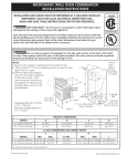
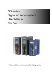
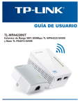
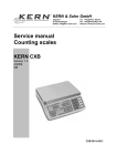
DIGIVIEW USER'S GUIDE
V2.6
TABLE OF CONTENTS
INTRODUCTION ................................................................................................................. 1
PREPARING DIGIVIEW ................................................................................................... 2
Getting started, LOGIN ................................................................................................... 2
Customizing plan drawing .............................................................................................. 3
Customizing labels ............................................................................................................ 6
Setting up the software users .......................................................................................... 7
PREPARING PLANS – EDIT WINDOW ..................................................................... 9
USING THE DIGIVIEW ................................................................................................... 11
Surveillance window ....................................................................................................... 11
Watching the floor plan.................................................................................................... 11
Partition toolbar................................................................................................................ 12
Log window...................................................................................................................... 12
Manage users window .................................................................................................... 12
Log query window ........................................................................................................... 14
The menu............................................................................................................................ 15
File.................................................................................................................................... 15
Tools................................................................................................................................. 15
Errors................................................................................................................................ 15
Setup................................................................................................................................. 15
Windows........................................................................................................................... 15
About................................................................................................................................ 15
INTRODUCTION
DIGIVIEW is an surveillance software for online monitoring and management of
DIGIPLEXNE security systems. The software is developed by Pragma Informatics Ltd. especially for
DIGIPLEXNE security panels and accessories. The purpose of DIGIVIEW is to provide the end-user
direct and full control over several security systems by a single computer.
The software is designed to operate on Microsoft Windows operating system. DIGIVIEW
displays control panel settings and security systems in a graphical, user-friendly environment. The enduser can manage the entire system simply clicking the mouse.
Simple, user-friendly and easy to navigate security systems.
1
PREPARING DIGIVIEW
The DIGIVIEW software offers a complete supervision of security systems to the users. The software
displays the system events in graphic mode and stores them in database. The users can manage these
systems depending on their authority.
After purchasing the CD the user has a software which runs in „demo” mode after installation. This
mode means full access to the software features (including 4 DigiplexNE control panels) and operation
of maximum 15 minutes. In order to use the software without limitation you have to register the
software. For the registration process, see document „DigiView registration process, disabling the
time limit”.
Getting started, LOGIN
At the start of the program the login window appears. In this window username and password must be
given. By default, master authority username and password are: demo/demo.
In order to launch the Digiview software, the SQL server must be running on some computer in the
network. If You have used the “Check Digiview_4” software, the checked server with password were
entered in these fields, so You do not need to change anything in the Login window, just type the
username/password. If You want to change (or check) database server settings manually, click in the
Details checkbox and required information will become visible.
Login
Into the server field, the name of the computer which has the SQL server must be given. (If the server
is running on the user's computer on the Windows tray at the bottom right hand corner move the mouse
onto the SQL server icon, leave it on, the name of the server computer will appear. This name must be
entered into the server field.)
2
The name of the Database: digiview_4
The server username and password are depending on the server's settings.
Click on the OK button to log in.
Customizing plan drawing
At first the software will try to connect to the systems through the configured COM ports (default: 1, 2,
3, 4) There is the communication status field in the bottom left hand corner. These four tetragon
indicate the communication status of the four systems (1, 2, 3, 4) by color. The colors are:
Green:
Communication ok
Red:
There is no DGP-NE panel on the configured COM port
Yellow:
System exists, connection failure (panel ID, PC password, registration code not
acceptable)
The next window appearing is the log window, containing text format information (time, event) of
events occurred.
Starting window
Click on the Configuration icon on the toolbar, Configuration window will appear. In the Module tab,
select the desired COM ports (see Appendix) and give the Panel ID and PC password. Click on the OK
button to exit and save.
After all the floorplan (*.dxf) must be imported. Click on the DXF icon. A notice will appear to close
the open floorplan. Click on the OK button then close the floorplan window.
3
Default floorplan closing
Click on the OK button to confirm. Click again on the DXF icon, a textbox will appear. Click on the
Browse (…) button and select the correct *.dxf file. To activate the changes restart the software.
If there is no green square in the communicaton status field, change the configuration settings.
The software is running in demo mode now. It means, the software establishes communication to
each systems but after 15 minutes it will shut down. To run the full program a registration code
must be given. To complete registration restart the software.
A toolbar appears with the partitions of the successfully connected control panels with the imported
floorplan in background.
4
Floorplan with the successfully connected Panels
You can toggle on/of the log window and partition buttons with the two icons on the right side end of
the icon line .
Buttons for toggling Log window and partition buttons
5
Customizing labels
Click on the Configuration icon, a configuration window will appear. You can set up the
Partition/Zone/User names in appropriate tab, by clicking the “Import names” button for each labels
group. The program reads the names from panels at about 2 labels/second speed. In case of importing
user names, the procedure can take up to one hour (3996 user names).The imported labels appear in a
separate window.
Label import window
In this window, You can select each line by double click, or use the “Select all” button. The selected
names get blue background. After selecting those labels You want to use in Digiview software, click
on the “Accept” button to overwrite the labels in Digiview database and close this window. You can
also edit each label in the Configuration window to change the label of every Partition, Zone, Door and
User in Digiview program.
Under the Current heading in the Events, Commands and Errors tabs You can change labels that will
be stored in the event list. In the same table, there is a “Soundfile” column that presents a path of the
.wav file that will be played when the mentioned event, command or error happens.
6
Sound import for Events
Selecting a file can be done by clicking in the “Soundfile” column next to the event/Command/Error
we want to set up, and after that on the binocular icon on top of the table. A browse window will
open, and You can find and open the desired audio (.wav) file.
The software will play the selected audio when the specific event, command or error occurs.
To activate changes restart the software.
Setting up the software users
Click on the Setup in the toolbar, select User groups. In this panel user can define user groups with
permissions.
Managing users
7
Click on the „+” button in the Group heading on the left side to create a group.
To delete selected group use „-” button.
To change the name of the group use the third buttton.
The black triangle and the blue color shown next to the name of the group indicates the currently
selected group. To add, delete or modify users that are in the selected group (have the same
permissions), use the buttons under “Users” tab. When You add new or edit an existing user, a new
window will appear, with more information about the selected user (Full name, User name and
password).
Configuring Permissions
You can configure the selected group's permissions in the right side window, under “Permissions” tab.
Click in the checkboxes on the right side window to add the described right to every user in the
selected group.
After the modification, click Close in the bottom right hand corner to quit settings.
To activate changes restart the software.
8
PREPARING PLANS – EDIT WINDOW
Switching to Edit mode (selecting the “pencil icon” can be done only if the logged user has the
permission to edit (see “setting up the software users” section)
Click on the Edit („pencil”) icon. The Partition toolbar disappears, only the header of the window is
visible. You can toggle on/of the log window and partition buttons with the last two icons (see page5).
The floor plan can be “grabbed” and moved with the left mouse button. To zoom in and out use the
mouse roll or use the two buttons in the bottom left corner.
After setting the right view, click the right mouse button onto the place where the item would be
placed. A menu appears, providing a choice to Add device (zone), Add door or Add text.
Placing a device
Click on Add text to put a new label in the floorplan.
Click on Add device and a new window appears. In this window, in the roll-down list You can choose
one from the four systems and after that, select the zone You would like to place on drawing.
Adding a device
The software automatically selects the right partition the zone belongs to.
9
In the Description field user may type a text such as the name of the zone, which will appear in the
floor plan. Select the desired icon that will present tis zone on the floorplan, and confirm all settings by
clicking on the OK button.
If You select the “Add door from the menu, similar window will appear, where You can select the
parameters (panel, door and a description)of the door You would like to place on the plan as a new
icon. This icon will present the door’s state with it’s colour.
Repeat these procedures to insert another device/Door /Label until You have added all zones/doors
and labels You would like to see in graphical presentation of the system.
Adding a door
To grab and move the Device/Door/Text use the left mouse button. To move the whole floorplan click
the left mouse button outside the devices.
Click the right mouse button on the device and a menu appears.
Device modification
In this menu, You can choose to delete the selected item from the plan, to modify the settings (zone,
label, shape) or to set the view „as default zoom for this device”.
Click on the Set as default zoom for this device and the program will save the current position and
zoom, to be displayed as default view for the selected zone. When You click on some event in the log
window that was affecting some concrete zone, the screen will jump to the saved “Default zoom” view
for that device.
After these operations, the default settings have been configured, the software is ready to use
10
.
USING THE DIGIVIEW
Surveillance window
Watching the floor plan
The colours of the detector's icon indicate the status of the detectors:
Zone closed – normal state, icon presented only
Zone opened - a green corner is blinking
armed - red background is added to the icon
bypassed – a yellow corner is blinking
in alarm – a red corner is blinking
trouble – a blue corner is blinking
Using the mouse or the “Zoom buttons” (left bottom of screen), You can change the change the area of
the plan that is presented. You can also change the presented area of the plan, using a left mouse
button anywhere on the plan- “grab and move” the whole plan in any direction. You can toggle On/Off
the Partition toolbar and the log window using the icon buttons, to use the whole screen for plan
viewing.
Buttons for toggling Log window and Partition buttons
6
In case of alarm, a new textbox appears, containing all alarm events. This box wil dissapear when the
alarm was acknowledged, by clicking on the button on bottom of the box.
Alarm events window
11
Partition toolbar
Each on-line panel has a row of buttons, so does up to 4 x 8 buttons. Each button has label as defined
in the configuration window. The colour of the button indicates the status of the partition.
Disarmed – normal state, grey colour
Armed - red
In alarm – black-red blinking
trouble – light blue
Click the left mouse button on the partition button to select all zones on floorplan that are assigned to
that partition. To deselect all click the left mouse button again on the name.
Click the right mouse button on the partition label. A menu appears. In this menu user can monitor the
status of the partition (Full Arm, Stay Arm, Instant Arm, Force Arm, Disarm).
Log window
The events appear right away as they occur. User can scroll, search among events. If the last event has
been selected the new events will scroll the event list and the last event that happened will be always
placed in the last visible line of the log window. If not the last event has been selected, the event list
window will not scroll when new event is added to the list. Only the events that happened since the last
starting of the DigiView will be available in this log screen. Events that happened before, can be
reached only with the “Log query window”.
If You double click (left mouse button) on some event in this window, a floor plan will jump to default
view for the affected zone (this view can be saved in Edit mode (pencil icon in toolbar), with the right
click on the desired zone/door. If the event was nat affecting just one zone, but a whole partition
(armed, ready,…), double click on the event will cause the floor plan would jump to position so all
zones in floor plan that are assigned to the affected partition will be visible on screen, and each zone
icon will be marked and connected to other zones with blue line (same as left click on partition button
in partition toolbar). You can disable this marking with a left click on affected partition button in
partition toolbar.
Manage users window
The Window that provides comfortable handling of all users in the system can be reached from a
menu (Tools/Manage users), or by clicking on the icon in toolbar.
On the left side, there is a list of all users in the system. The second row of the table is the label that is
used in DigiView for this user. All labels can be imported from the configuration window. On the right
side of the screen, all parameters of the selected user (from the table on the left) are presented. Boxes
that are grey mean that settings and User name that are valid for this user were not uploaded yet, and
You should double click the user in the table (on left), or use the buttons marked on the picture:
Upload buttons for user settings and names
12
Although their default name in Digiview is a simple count from 1 to 3996, physically each user is
present in only one of four systems. This means users from 1- 999 are users that are set in Control
panel 1 (Digiplex NE system 1), users from 1000-1998 are users in System 2, etc. If You select a user
from a table on the left side, You can see it’s location in Digiplex systems on top of the right half of
the Manage User window.
Manage users window
After the user’s settings were uploaded, You can edit the settings, or change the name (label) for this
user. Each setting in this field corresponds to “User options” in Digiplex NE system. For explanations,
please check the “System manager manual” for Digiplex NE systems.
In order to these (changed) settings and labels become valid, You must download all to the live
systems. Naturally, the settings and label are treated separately, so You must download both (same as
for upload), using two buttons next to “Upload buttons” for name and for settings.
To change the name of the user in DigiView software (used in the event list), use the “Store in DB”
button (next to user name field). When You click on it, the label that was entered in the “User name”
field will be stored in database, and this name will be used from that moment for all events that contain
this user. At the same moment, this name will replace the previous one in the “Current” row of the
table on left side of User manage window.
13
Log query window
Click on the „magnifier” icon and a new window appears. Use the checkboxes and roll-down menus to
configure the Log filter. When all checkboxes are empty and You click on the “Start” button, all
logged events will be displayed. The listed events can be filtered by three limitations:
1. Time interval,
2. Affected object (Panel, Partition, Zone, Door, or User)
3. Type of desired event ( Event, Command or Error)
To activate flitering, click in the checkboxes of the desired filtering, select the limits and use the
“Start” button to list all events from database that fulfill selected criteria.
You can also use multi-layer filtering, for example: Check when did the User 33 (John Smith)
approached Door 33 during last week (time interval 2006.04.10 – 2006.04.16). Or check the Errors in
Partition 28, that belongs to Panel 3. A Partition or zone can be selected ONLY after the
corresponding Control panel has been selected.
Event filter setup
ATTENTION: Using Empty log button will erase the whole event database!
Use the Export to txt file button to save the displayed events in txt format.
To exit the window, click the Close window.
14
The menu
File
Import DXF file: An exists .dxf file may be imported as floorplan.
Exit: Quit the software.
Tools
Login: The software tries to connect to the configured panels through the configured COM ports.
Logout: All of the communication to the panels will be stopped.
Configuration: Switch to “Configuration” window
Manage users: Switch to “Manage users” window
Surveillance: Switch to Surveillance window
Edit devices: The floorplan editor window appears.
Show log: (Latched) If ticked, the Log displayed in the bottom of the screen. If not ticked, no log will
be displayed.
Log query: The log filter setup window appears.
Errors
To display the troubles that are present in some system, select the appropriate sub-menu line. If there
is an error in some system the relating icon will be activ, and You will be aqble to click on it and see
the error. You can change the presented system in the menu, and only those errors that are active in the
selected system will be highlighted with red.
Setup
- Login as different User: A different user may log in.
- Change user password: Change current user's username and password.
-User groups: See above.
Windows
Contains tools for arranging opened windows.
About
Provides DigiView version number and information about the software creators.
15