1
EF
User Guide
FXM5
Part Number: 0410-0011-05
Issue Number: 5
www.controltechniques.com
Safety Information
Persons supervising and performing the electrical installation or maintenance of a
Drive and/or its external Option Unit must be suitably qualified and competent in
these duties. They should be given the opportunity to study and if necessary to discuss this User Guide before work is started.
The voltages present in the Drive and external Option Units are capable of inflicting
a severe electric shock and may be lethal.
The Stop function of the Drive does not remove dangerous voltages from the terminals of the Drive and external Option Unit. Mains supplies should be removed before
any servicing work is performed.
The installation instructions should be adhered to. Any questions or doubt should be
referred to the supplier of the equipment. It is the responsibility of the owner or user
to ensure that the installation of the Drive and external Option Unit, and the way in
which they are operated and maintained complies with the requirements of the
Health and Safety at Work Act in the United Kingdom and applicable legislation and
regulations and codes of practice in the UK or elsewhere.
The Drive software may incorporate an optional Auto-start facility. In order to prevent the risk of injury to personnel working on or near the motor or its driven equipment and to prevent potential damage to equipment, users and operators, all
necessary precautions must be taken if operating the Drive in this mode.
The Stop and Start inputs of the Drive should not be relied upon to ensure safety of
personnel. If a safety hazard could exist from unexpected starting of the Drive, an
interlock should be installed to prevent the motor being inadvertently started.
General Information
The manufacturer accepts no liability for any consequences resulting from inappropriate, negligent or incorrect installation or adjustment of the optional operating parameters of the equipment or from mismatching the Drive with the motor.
The contents of this User Guide are believed to be correct at the time of printing. In
the interests of a commitment to a policy of continuous development and improvement, the manufacturer reserves the right to change the specification of the product
or its performance, or the contents of the User Guide, without notice.
All rights reserved. No part of this User Guide may be reproduced or transmitted in
any form or by any means, electrical or mechanical including photocopying, recording or by any information storage or retrieval system, without permission in writing
from the publisher.
Copyright
© Septemaber 2002 Control Techniques Drives Ltd
Issue Code: 5
Contents
1
Introduction
1
1.1
1.2
1.3
Purpose of the FXM5 field-current controller
System control modes
Main features
1
1
1
2
Data
3
3
Installation
4
3.1
3.2
3.3
3.4
3.5
3.6
3.7
3.8
3.9
Hazardous areas
Environment
Mounting instructions
Cables and fuses
Access to the power and signal connectors
Power connections
Armature connections and fuses
EMC recommendations
Signal connections
4
Setting Up
4.1
4.2
4.3
4.4
4.5
4.6
4.7
4.8
Control-system description
Control-circuit description
Setting the thyristor control mode
Setting the value of IFmax
Changing the DCCT primary winding turns
Setting the armature-voltage range
Setting the maximum and minimum field current
Adjusting the armature-voltage threshold
5
Fault Finding
FXM5 User Guide
Issue Number: 5
4
4
4
5
6
7
8
9
11
15
www.controltechniques.com
15
16
17
19
21
22
22
24
25
Declaration of Conformity
Control Techniques, The Gro, Newtown, Powys, UK. SY16 3BE
The AC variable speed drive product FXM5, current range 2A to 20A has been
designed and manufactured in accordance with the following European harmonised,
national and international standards:
EN60249
Base materials for printed circuits
IEC326-1
Printed boards: general information for the specification writer
IEC326-5
Printed boards: specification for single- and double-sided printed boards
with plated-through holes
IEC326-6
Printed boards: specification for multilayer printed boards
IEC664-1
Insulation co-ordination for equipment within low-voltage systems:
principles, requirements and tests
EN60529
Degrees of protection provided by enclosures (IP code)
UL94
Flammability rating of plastic materials
This product complies with the Low Voltage Directive 73/23/EEC and the CE Marking
Directive 93/68/EEC.
W. Drury
Executive VP Technology
Date: 9 December 1996
This electronic drive product is intended to be used with an appropriate motor,
controller, electrical protection components and other equipment to form a
complete end product or system. It must only be installed by a professional
assembler who is familiar with requirements for safety and electromagnetic
compatibility ("EMC"). The assembler is responsible for ensuring that the end
product or system complies with all the relevant laws in the country where it is to
be used. Refer to the product manual or EMC data sheet for further information
on EMC standards complied with by the product, and guidelines for installation.
www.controltechniques.com
FXM5 User Guide
Issue Number: 5
1
Introduction
1.1
Purpose of the FXM5 field-current controller
The FXM5 field-current controller allows wound-field DC motors to be run at speeds
above base-speed. This is achieved by automatically reducing the field current which
reduces the magnetic flux. This, in turn, reduces the back-emf in the armature windings.
The result is an increase in armature current, and a consequent increase in speed.
When a motor is operated under these conditions above base-speed, power output from
the motor remains constant since the available torque reduces in inverse proportion to
increases in speed.
The motor is normally controlled in a closed-loop system by a variable speed drive
(such as a Control Techniques Mentor II Drive).
1.2
System control modes
The FXM5 controller can be used in the following system control modes:
1.2.1
Analog control
The motor speed is controlled by a variable speed drive which varies the armature
voltage. The FXM5 controller monitors the armature voltage. When this has reached a
preset level (usually the level for base-speed), the controller reduces the field current.
This gives automatic field weakening resulting in constant power above base-speed.
A suitable speed feedback device must be fitted to the motor shaft and used by the
Drive.
1.2.2
Digital control
The motor speed is controlled by a Control Techniques Mentor II Drive which varies the
armature voltage, and controls the field current using the FXM5 controller.
Basic PI loop gain adjustments can be made in the Mentor II Drive. Highly precise
control of motor speed above base-speed can be obtained.
The FXM5 controller can be controlled by the Mentor II Drive to give automatic field
weakening (see Analog control above), or to reduce the field current to a preset level
when a specified speed has been reached.
A suitable speed feedback device must be fitted to the motor shaft and used by the
Drive.
1.2.3
External control of the field current
An external source can be used for either of the following:
•
•
1.2.4
Field weakening by applying a variable field-current reference signal (e.g. from a
system controller such as a PLC). A suitable speed feedback device must be fitted
to the motor shaft and used by the system controller.
Fixed level of field current (e.g. using an external preset potentiometer).
Internal control of the field current
The field current is set at a fixed level using a preset potentiometer in the FXM5
controller. The motor can then be run with a reduced field current at fixed or varying
speed.
1.3
1.3.1
Main features
AC supply requirements
The FXM5 controller operates on a single-phase AC supply. The AC supply is rectified
and controlled by thyristors which can be used to give half-control or full-control as
required.
FXM5 User Guide
Issue Number: 5
1
www.controltechniques.com
The AC supply to the FXM5 controller must be isolated externally.
1.3.2
Field economy
Control of the field current can be over-ridden to a field-economy level using an external
switch. This can be used for the following purposes:
•
•
1.3.3
Over-ride the normal field current when the motor is stationary in order to prevent
over-heating of the motor
By keeping the motor warm, prevent atmospheric condensation in the motor when it
is not in use
Mounting arrangement
The FXM5 controller is contained in a module which must be mounted on a vertical
surface. Heat generated in the thyristors is dissipated to the air by a finned heatsink.
Ingress protection conforms to IP10.
1.3.4
Controls and indicators
Recessed preset potentiometers and LED indicators on the front panel of the module
are used for setting up and monitoring the FXM5 controller.
1.3.5
Protection
Change-over relay contacts are operated when the field current reduces to the minimum
field current set by the user. The relay contacts can be used to disconnect the motor to
prevent run-away in the event of loss of field current.
2
www.controltechniques.com
FXM5 User Guide
Issue Number: 5
2
WARNING
Data
The voltages present in the FXM5 controller are capable of inflicting a severe
electric shock and may be lethal. The Stop function of the Drive does not remove
dangerous voltages from the FXM5 controller or the driven machine.
AC supplies to the FXM5 controller must be disconnected at least 5 minutes
before any cover is removed or servicing work is performed.
Electrical
Permissible AC supply voltage for the controller
power supply
220 ~ 254V ±10%
380 ~ 440V ±10%
AC supply frequency
48Hz ~ 62Hz
Permissible AC supply voltage for the thyristor
bridge
0 ~ 480V ±10%
Number of AC supply phases
1 (or across 2 phases)
Range of control of the field-winding voltage
(depending on AC supply voltage)
0V ~ 430V
Field current
20A maximum
Armature voltage
220V ~ 600VDC
Field failure relay contact ratings
250V, 3.5A DC maximum
1000VA, 200W maximum
Environmental
Ingress protection
IP10 in accordance with IEC539
Operating temperature range
0°C ~ +50°C (32°F ~ 122°F)
Storage temperature range
-40°C ~ +70°C (-40°F ~ 128°F)
Humidity
85% maximum, non-condensing
Derating for altitude
Maximum altitude without derating is 1000m
(3200ft). De-rate maximum field current by 1%
for each additional l00m (320ft), up to a
maximum of 4000m
Heat dissipation
75W maximum
Electromagnetic compatibility (EMC) emissions
When all the following conditions are met, the
installation can meet the requirements for
conducted emissions of EN50081-2:
The specified RFI filter (or ferrite absorber ring
and capacitor network) is used
The recommendations for the wiring
arrangements are as follows
RFI filter
Steatite P2E/025/M7/Physical
Overall dimensions (when installed)
Width: 250mm (9.843in)
Height: 187mm (7.362in)
Depth: 112mm (4.409in)
Weight
2.5 kg (6 lb)
FXM5 User Guide
Issue Number: 5
3
www.controltechniques.com
3
WARNING
WARNING
Installation
The equipment enclosure is rated at IP10 in accordance with IEC539. It is
designed for installation within a protective enclosure which prevents
unauthorised access except for trained service personnel, and prevents
contamination with conductive dust and condensation.
The voltages present in the FXM5 controller are capable of inflicting a severe
electric shock and may be lethal. The Stop function of the Drive does not remove
dangerous voltages from the FXM5 controller or the driven machine. AC supplies
to theFXM5 controller must be disconnected using an approved isolation device
before any cover is removed or service work is performed.
Electric shock risk
WARNING
If the FXM5 controller has been energized, the supply must be isolated for at least
five minutes. This allows the internal capacitors to discharge fully before work
may continue.
Ground connections
WARNING
3.1
The ground connections should be inspected and tested at appropriate and
regular intervals.
Hazardous areas
Approval and certification for hazardous areas should be obtained for the complete
installation of the motor, Drive and FXM5 controller.
3.2
Environment
In accordance with the IP10 rating of the FXM5, the FXM5 must be located in an
environment that is free from dust, corrosive vapors, gases and all liquids, including
condensation of atmospheric moisture (i.e. pollution degree 2 as required by UL840 and
IEC664-1).
If condensation is likely to occur when the FXM5 is not in use, install an anticondensation heater. This heater must be switched off when the FXM5 is in use;
automatic switching is recommended.
Install the FXM5 vertically for best flow of cooling air. When the FXM5 is installed in an
enclosure, install the FXM5 as low as possible (without contravening EMC
requirements).
Observe the requirements for ambient temperature if the FXM5 is to be mounted directly
above any heat generating equipment (such as a Drive).
3.3
Mounting instructions
Refer to section 3.8 EMC recommendations on page 9. Install the FXM5 controller on a
vertical surface (enclosure back-plate) with the heatsink fins vertical. Use the fixing
holes in the mounting brackets.
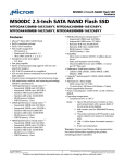
Allow at least 100mm (3.937in) clearance above and below the FXM5 controller to allow
free air-flow through the heatsink. Allow at least 3mm (0.118in) clearance each side of
the FXM5 controller.
4
www.controltechniques.com
FXM5 User Guide
Issue Number: 5
26mm (1.024in)
7mm (0.276in)
150mm (5.906in)
112.5mm (4.429in)
187mm (7.362in)
176mm (6.929in)
225mm (8.858in)
Figure 3-1 Mounting details
3.4
WARNING
Cables and fuses
The AC supply inputs in the FXM5 controller are fitted with fuses for protection
against overload and short circuits in the FXM5 controller and field-winding of the
motor. These fuses will not protect the supply cables to the FXM5 controller. The
table shows recommended cable sizes and fuse ratings for a number of current
levels. Failure to observe this recommendation will cause a risk of fire.
Wiring must be in accordance with local regulations and codes of practice. The
table shows typical cable sizes for power input and output wiring. In the event of
a conflict, local regulations prevail.
WARNING
For the following power connections...
• AC supply to the isolator and fuses
• Isolator and fuses to the Drive
• Drive to the motor
• External braking resistor to the Drive (when required)
...use the following:
•
•
3-core and 4-core pvc-insulated cable with copper conductors having a temperature
rating not less than 60/75°C and laid in accordance with defined conditions. Refer to
EMC recommendations later in this chapter for shielding requirements.
The wiring must conform to local regulations and codes of practice. Refer to the
following table for the size of the AC supply and field-winding cables. In the event of
conflicting data, local regulations prevail.
FXM5 User Guide
Issue Number: 5
5
www.controltechniques.com
Cable size
Maximum current
and fuse rating
mm 2
AWG
A
1.0
18
2
1.5
16
5
2.5
14
10
4.0
10
20
4.0
10
20
Fuses fitted to the FXM5 controller printed-circuit board are as follows:
3.5
Fuse
Rating
Type
Protects...
CT Part number
FS1
FS2
500mA
30mm
Control-circuits power supply
3537-3251
FS3
FS4
20A
HRC
Thyristor bridge and field
weakening
3537-3252
Access to the power and signal connectors
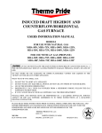
Remove the four corner screws and the front cover. The connectors are mounted on the
printed-circuit board which is now exposed.
Figure 3-2 Locations of the ground, power and signal connectors, fuses and
jumpers
6
www.controltechniques.com
FXM5 User Guide
Issue Number: 5
3.6
Power connections
Terminal
A1
A2
3.6.1
Function
Notes
Armature-voltage input
A1 - Positive
A2 - Negative
(With forward rotation)
F1
F2
Field-winding output
F1 - Positive
F2 - Negative
L1
L3
AC supply
See AC supply connections
E1
E3
Alternative AC supply
See AC supply connections
AC supply connections
Using an alternative AC supply
The AC supply applied to terminals L1 and L3 supplies the following:
•
Field winding of the motor (through the thyristor bridge)
•
Power supply for the control-circuits
The AC supply voltage must be in the range specified in Data on page 3 for the controlcircuits power supply. If the voltage is less than 220V ±10%, the control-circuits power
supply must be supplied by an alternative AC supply having an acceptable voltage. Use
the following procedure:
NOTE
1. Remove fuses FS1 and FS2 from the printed-circuit board in order to ensure
isolation between the alternative AC supply and the field-winding AC supply.
2. Connect the alternative AC supply to terminals E1 and E3. Ensure that the
alternative supply is connected so that the voltage applied to E1 is in phase with the
voltage applied to L1.
3. Ensure that both connections of the alternative supply are protected with 500mA
fuses.
If the voltage rating of the field is much lower than the supply voltage it is
advisable to use a transformer to reduce the supply voltage. This maximises the
resolution of the controller and prevents the possibility of excessive voltage being
applied to the field winding.
Figure 3-3 Connecting an alternative AC supply in phase with the field-winding
supply
FXM5 User Guide
Issue Number: 5
7
www.controltechniques.com
Using a Mentor II Drive
When using the FXM5 controller with a Mentor II Drive, ensure that terminals L1 and L3
of the controller are connected to the same phases as L1 and L3 in the Drive.
3.6.2
AC supply voltage
Figure 3-4 Locations of jumpers LK5 and LK6
Set jumpers LK5 and LK6 for the AC supply voltage. (This may be the voltage applied to
terminals L1 and L3, or E1 and E3 (see Using an alternative AC supply on page 7). Both
jumpers must be set for the same voltage.
3.7
Armature connections and fuses
Connections
Make armature connections to terminals A1 and A2 as follows:
System control mode
Analog control
Connect...
Yes
Digital control
No
External control of field current
No
Internal control of field current
No
Fuses
Protect each armature connection with a 2ADC fuse.
8
www.controltechniques.com
FXM5 User Guide
Issue Number: 5
3.8
EMC recommendations
Figure 3-5 EMC wiring recommendations
To minimize radio-frequency emissions, it is necessary to install the FXM5 in a steel
enclosure and pay attention to the arrangement of the wiring inside the enclosure. Any
number of FXM5 controllers may be installed in an enclosure.
FXM5 User Guide
Issue Number: 5
9
www.controltechniques.com
Figure 3-5 shows an example of wiring arrangements for minimum radio-frequency
emissions. The actual arrangement used will have to be adapted to individual
requirements.
The following conditions must be met:
•
•
•
•
3.8.1
The environment is acceptable (see section 3.2 Environment on page 4)
The maximum permissible ambient temperature is not exceeded
The EMC requirements are met
The electrical installation meets safety requirements
Motor cable
In order to meet the EMC emissions requirements, it is preferable that one of the
following conditions applies for the motor cable:
•
•
•
•
3.8.2
If the cable is to be entirely enclosed in grounded metal ducting, the cable does not
need to be shielded or armoured.
If the FXM5 is to be mounted in a machine that has a grounded metal case, and the
motor cable is to be contained inside the case, the cable does not need to be
shielded or armoured.
If the cable is to be exposed, it should be armoured or shielded. Alternatively,
unshielded cable could be used if an RFI filter is included in the output circuit of the
FXM5.
If the length of the motor cable does not exceed 50 metres, very little radiation
should be produced. In this case, unshielded cable may be used on condition that
the EMC emissions requirements of the installation are considered.
RFI filter
An RFI filter type P2E/025/M7/- must be connected as shown in the AC supply circuit to
the FXM5. Mount the RFI filter beneath the FXM5 with a clearance of 300mm (12in).
Use the same type of filter if an RFI filter is to be included in the output circuit of the
FXM5.
CAUTION
3.8.3
The filter must be used in conjunction with a suitable RFI filter for the armature
supply. The filter input must obtain its supply from the input of the armature filter
and line chokes, otherwise it may be over-heated and possibly damaged by the
armature voltage notching.
Ground connections
The ground stud on the heatsink of the FXM5 must be connected to the power ground
bus-bar. This bus-bar must be connected to the enclosure ground by a safety ground
connection. It is essential that these connections are permanently installed, and cannot
be inadvertently disconnected.
The size of external grounding terminals should be appropriate to the size of the
grounding cables.
Ground loop impedance must conform to the requirements of local industrial safety
regulations.
Do not connect the signal 0V common connections to ground at the FXM5. Connect
them to ground at the isolated 0V bus-bar.
10
www.controltechniques.com
FXM5 User Guide
Issue Number: 5
3.9
3.9.1
Signal connections
Analog control
Figure 3-6 Power and signal connections for analog control
Make signal connections to terminal block TB1, as follows:
TB1
Function
1
Field economy contact
2
0V common
3
Field-current amplifier input
Do not connect
4
-15V, 10mA max. output
Use to supply external devices
5
+15V, 10mA max. output
Use to supply external devices
6
Field-current output signal
0 to 10V represents 0 to IF max.
Armature-voltage output signal
0 to ±10V represents 0 to ±600V armature
voltage
7
8
9
Common contact
Field-current failure relay
10
3.9.2
Connect to terminal 2 for normal
operation
Disconnect for field economy
Contact closed when field current is
normal
Contact open when field current is normal
Digital control
Figure 3-7 Power and signal connections for digital control
FXM5 User Guide
Issue Number: 5
11
www.controltechniques.com
Digital control can be obtained only by connecting a Control Techniques Mentor II Drive
to PL1 of the FXM5 controller using the 10-way ribbon cable supplied with the controller.
When the cable is connected, the FXM5 control circuits are automatically disconnected
from the thyristor bridge driver N5; The Mentor II Drive then controls the bridge driver
directly.
Use Menu-6 parameters in the Mentor II Drive to set up and control the FXM5 controller.
Remove the following jumpers from the power boards of the Mentor II Drive:
3.9.3
3.9.4
Model
Jumper
M25 to M210
LK1 and LK2
M350 to M1850
LK1
Connections to the Mentor Drive
Model
Mentor Power Board
M25-M75
MDA75
Connector Designation
PL6
M25R-M75R
MDA75R
PL6
M105-M210
MDA210
PL6
M105R-M210R
MDA210R
PL6
M350-M1850
MDA6
PL16
M350R-M1850R
MDA6
PL16
External control of the field current (variable or fixed levels)
Figure 3-8 Power and signal connections for external control of the field current
12
www.controltechniques.com
FXM5 User Guide
Issue Number: 5
Make signal connections to terminal block TB1, as follows:
TB1
Function
1
Field economy contact
2
0V common
3
Not used
Field-current amplifier input
Apply an external field-current reference signal (0
to -10V)
Remove jumper LK4
-15V, 10mA max. output
Use to supply external devices
(e.g. external field-current reference potentiometer)
5
+15V, 10mA max. output
Use to supply external devices
6
Field-current output signal
0-10V represents 0 to I F max
7
Armature-voltage output signal
Not used
4
8
9
10
Common contact
Field-current failure relay
Contact closed when field current is normal
Contact open when field current is normal
The field current must not be allowed to become zero while the motor is running.
CAUTION
Cut the wire jumper LK4 since stages N1, N2 and N3 are not used and must not affect
the system (see section 4.2 Control-circuit description on page 16).
Figure 3-9 Location of wire jumper LK4
FXM5 User Guide
Issue Number: 5
13
www.controltechniques.com
3.9.5
Internal control of the field current (fixed level)
Figure 3-10 Power and signal connections for internal control of the field current
Make signal connections to terminal block TB1, as follows:
TB1
1
Function
Field economy contact
2
0V common
3
Field-current amplifier input
Do not connect
4
-15V, 10mA max. output
Use to supply external devices
5
+15V, 10mA max. output
Use to supply external devices
6
Field-current output signal
0-10V represents 0 to I F max
7
Armature-voltage output signal
Not used
8
9
Common contact
Field-current failure relay
10
3.9.6
Connect to terminal 2 for normal operation. Open
circuit for field economy.
Contact closed when field current is normal
Contact open when field current is normal
Field economy
When the FXM5 controller is in normal use, connect TB1 terminal 1 to terminal 2. This
can be achieved using external contacts. When field economy is required, the contacts
should be opened. The field current is reduced to the minimum value set using RV2.
When the FXM5 is being controlled from the Mentor using Menu 6 the field current can
be reduced by controlling parameter 6.14. The field can be automatically reduced if the
armature is disabled. This function is controlled by parameter 6.12, 6.15.
14
www.controltechniques.com
FXM5 User Guide
Issue Number: 5
4
Setting Up
4.1
Control-system description
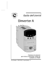
Figure 4-1 Control of armature voltage and field current with varying motor speed
Refer to Figure 4-1. The FXM5 controller maintains the field current IF at a fixed value
until base speed n is reached (detected by the armature voltage VA reaching a
maximum value). Attempts by the Drive to increase the speed by further increasing the
armature voltage causes the controller to reduce the field current. Because the Drive,
FXM5 controller and motor operate in a closed loop, the armature voltage remains
constant when the speed is varied above base-speed, but the field current is reduced in
inverse proportion to increases in speed. For example, to allow the motor speed to
reach double the base-speed, the field current must be halved.
FXM5 User Guide
Issue Number: 5
15
www.controltechniques.com
4.2
Control-circuit description
Figure 4-2 Main elements of the control circuit
Refer to Figure 4-2. The control circuit comprises four main elements, as follows:
• Armature-voltage monitor (N1, N2)
• Field-current limiter (N3)
• Field-current amplifier (N4)
• Thyristor-bridge driver (N5)
The elements that are used depend on the system control mode that is in operation.
4.2.1
Main elements
The armature-voltage is applied to amplifier N1. The output is compared with a voltage
reference N2. Preset potentiometer RV1 (MAX ARM V) and jumper LK2 are used to
adjust the threshold level. When a Mentor II Drive is used parameter 6.07 sets the
threshold. When the threshold level is not reached, the resulting signal causes the fieldcurrent limiter (N4) and thyristor-bridge driver (N5) to apply full voltage to the field
winding of the motor. When the threshold is reached, the field-current limiter (N4) and
thyristor-bridge driver (N5) cause the field-winding voltage to be reduced.
A direct-current current-transducer (DCCT) in the field-winding circuit monitors the field
current. The output of the DCCT is applied to a negative feedback loop so that, by
varying the field-winding voltage, the FXM5 controller is in control of the field current.
The setting of jumper LK1 and the number of primary-winding turns through the DCCT
define the absolute maximum current (IFmax) that can be produced by the controller
16
www.controltechniques.com
FXM5 User Guide
Issue Number: 5
(see section 4.5 Changing the DCCT primary winding turns on page 21). This value
should be set at the nearest value above the required maximum field current.
Preset potentiometer RV2 (SET MAX FIELD) is used to set the required maximum field
current as a proportion of IFmax. This current level occurs when the armature voltage is
below the preset threshold. LED2 indicates when the field current is at the maximum
level set using RV2. When a Mentor II Drive is used, the required maximum current can
be set using parameter 6.08.
Preset potentiometer RV3 (SET MIN FIELD) and switch SW1 are used to adjust the
minimum level of field current as a proportion of the current set using RV2. When SW1
is pressed, the LED bar indicator indicates proportion of the maximum current set using
RV2. The minimum level should be set for maximum required motor speed. When a
Mentor II Drive is used, the required minimum current can be set using parameter 6.10.
LED3 indicates when the field current is at or below the minimum level set using RV3.
The field-current feedback signal is monitored by an LED bar indicator, (LED1) and N6.
The LED bar indicates proportion of absolute maximum current (IF max) in steps of 0.1
(10%).
When the FXM5 controller is operating normally, field-failure relay RL1 is energized by
N6. When the field current is detected by N6 to be below the setting of RV2 (or the
minimum current set by a Mentor II Drive), the relay is de-energized. The contacts can
be used to break the AC supply to the armature.
4.3
Setting the thyristor control mode
All system control modes
4.3.1
Description
The thyristors are arranged as a full-wave bridge rectifier. The thyristors can be
controlled so that the bridge gives half-control or full-control. In both cases, full-wave
rectification is obtained. The results are as follows:
Half-control
Figure 4-3 Waveforms resulting from half-control
FXM5 User Guide
Issue Number: 5
17
www.controltechniques.com
Full-control
Figure 4-4 Waveforms resulting from full-control
4.3.2
Recommendations
Half-control
Normally use half-control, since this generally produces a lower amplitude of current
ripple. This results in lower torque ripple in the motor.
Full-control
Full control causes the thyristor bridge to force the field current more rapidly towards
zero at each half cycle. This increases the amplitude of the ripple current, but gives
faster control of the field-current level. Use full-control under the following conditions:
18
•
When very rapid field-weakening is required
•
L
Motors that have an unusually long electrical time-constant æ ----ö
è Rø
www.controltechniques.com
FXM5 User Guide
Issue Number: 5
4.3.3
Procedure
Figure 4-5 Location of jumper LK3
Set the required thyristor control mode using jumper LK3.
Key to symbols
Half-control position
Full-control position
4.4
Setting the value of IFmax
All system control modes
4.4.1
Description
The maximum field current (IFmax) that can be delivered by the FXM5 controller
depends on the following:
•
•
Number of primary-winding turns through the DCCT
Setting of jumper LK1
Refer to the following table.
FXM5 User Guide
Issue Number: 5
19
www.controltechniques.com
Maximum field Number of primary
current
turns
1
10
2
10
3
5
4
5
5
4
6
3
7
2
8
2
9
2
10
2
11
1
12
1
13
1
14
1
15
1
16
1
17
1
18
1
19
1
20
1
LK1 setting
15/Np
ü
ü
ü
ü
ü
ü
ü
20/Np
ü
ü
ü
ü
ü
ü
ü
ü
Setting of
parameter 6.11
1
2
3
4
5
6
7
8
9
10
11
12
13
14
ü
ü
ü
ü
ü
15
16
17
18
19
20
The maximum field current is derived as follows:
20 15
IF max = ------- or ------NP N P
When the FXM5 controller is used with a Mentor II Drive, parameter 6.11 must be set at
the value stated in the table.
The FXM5 controller is supplied having two turns through the DCCT. (The number of
turns is defined by the number of times the wire passes through the hole in the DCCT).
4.4.2
Procedure
Set the value of IFmax at the nearest value above the maximum required field current.
At a later stage, you can set the maximum field current at the required value using the
SET MAX FIELD potentiometer or parameter 6.08.
20
www.controltechniques.com
FXM5 User Guide
Issue Number: 5
Figure 4-6 Location of the DCCT and wire loop
4.5
Changing the DCCT primary winding turns
Use the following procedure to change the number of turns:
1. Disconnect the loop of wire from the spade connectors on the printed-circuit board
and remove the wire from the DCCT.
2. Use insulated wire of sufficient length for the required number of turns and ensure
the wire is of the correct size for the maximum field current. (Refer to Cables and
fuses on page 5)
3. Loop the wire through the DCCT in the same direction as the original wire.
4. Fit a 6.25mm (0.276in) spade receptacle to each end of the wire.
5. Connect the wire to the spade connectors on the board.
6. Set jumper LK1 at the setting given in the table.
Figure 4-7 Location of jumper LK1
FXM5 User Guide
Issue Number: 5
21
www.controltechniques.com
4.6
Setting the armature-voltage range
Analog control mode
Digital control mode
4.6.1
Procedure
Figure 4-8 Location of jumper LK2
Set jumper LK2 as follows:
Maximum armature voltage
4.7
Setting
0 ~ ±470V
<470
>±470V
>470
Setting the maximum and minimum field current
Analog control mode
External control of the field-current
Internal control of the field-current
During the following procedures, you will be required to apply AC power to the
FXM5 controller and the motor. Before applying AC power, ensure the following:
WARNING
The controller is correctly connected
The controller cover is securely fitted
22
www.controltechniques.com
FXM5 User Guide
Issue Number: 5
IF max
TEST
IF min
IF max
1.0
0.8
0.6
0.4
SET
MAX
FIELD
SET
MAX
ARM V
SET
MIN
FIELD
0.2
0
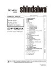
Figure 4-9 Locations of the controls and indicators on the front panel
4.7.1
Maximum current
Apply AC power to the FXM5 controller. Do not start the motor running.
Monitor the LED bar indicator and adjust the SET MAX FIELD potentiometer to set the
current at the required proportion of IFmax. Check that the IF max LED is lit.
Note that the LED bar indicator relates to the absolute maximum current that can be
produced by the controller as determined by the setting of jumper LK1 and the number
of primary-winding turns in the DCCT. The absolute maximum current is defined as
IF max. The title IFmax on the LED above the SET MAX FIELD potentiometer relates to
the maximum required current set using the potentiometer, not the absolute maximum
current of the FXM5 controller.
4.7.2
Minimum current
1. Press the TEST switch continuously. The LED bar indicator now shows the
proportion of current set using the SET MAX FIELD potentiometer.
2. Monitor the LED bar indicator and adjust the SET MIN FIELD potentiometer to set
the current at the required proportion of the maximum level. Check that the IF min
LED is lit.
The value of minimum field current that can be set is between 0.1 and 0.9 of the
maximum. The minimum current should be set to either of the following:
•
To just below the field current required for the maximum speed (e.g. for double
the base-speed, set the SET MIN FIELD potentiometer for just below half the
current set using the SET MAX FIELD potentiometer. The field-failure relay
will be de-energized when the field current reduces to the level set using the
SET MIN FIELD potentiometer.
•
To define a level for the field-failure relay to be de-energized, independently of
the minimum required field current.
3. Release the TEST switch.
4. Remove AC power from the FXM5 controller and from the field winding of the motor.
4.7.3
Fixed field current
Use the procedure given above to set the maximum field current. Set the minimum field
current at a level for the field-failure relay to be de-energized.
Set the MAX ARM V potentiometer at the fully clockwise position.
FXM5 User Guide
Issue Number: 5
23
www.controltechniques.com
4.8
Adjusting the armature-voltage threshold
Analog control mode
During the following procedure, you will be required to apply AC power to the
FXM5 controller and to run the motor. Before applying AC power, ensure the
following:
WARNING
The controller is correctly connected
The controller cover is securely fitted
The motor can be run safely
Use the following procedure to adjust the FXM5 controller to begin field-weakening at
the required armature voltage:
1. Set the SET MAX ARM V potentiometer at the fully clockwise position.
2. Apply AC power to the Drive and FXM5 controller.
3. Set the Drive to run the motor at base-speed, (or at the required speed if fieldweakening is to start at a lower speed).
4. Slowly turn SET MAX ARM V potentiometer anti-clockwise until the highest
illuminated segment of the LED bar indicator becomes extinguished.
5. Stop the motor and remove AC power from the system.
24
www.controltechniques.com
FXM5 User Guide
Issue Number: 5
5
Fault Finding
Users must not attempt to repair the FXM5 if it is faulty, nor carry out fault
diagnosis other than through the use of the diagnostic features described in this
section.
WARNING
Under no circumstances must the casing of the FXM5 be opened when the AC
supply is connected.
If the FXM5 is faulty, it must be returned to an authorized Control Techniques
distributor for repair.
Electric shock risk
WARNING
If the FXM5 controller has been energized, the supply must be isolated for at least
five minutes. This allows the internal capacitors to discharge fully before work
may continue. Refer to Safety information on the inside front cover of this user
guide.
Fault
Possible cause
Action
The AC supply isolator does
not close
The field current is low, causing
the field-failure relay to be deenergized.
LED bar indicator indicates
zero
Check the field winding
Faulty field-winding connections.
connections.
The SET MIN FIELD
Check and, if necessary, adjust
potentiometer is set at the fully
the SET MIN FIELD
anti-clockwise position.
potentiometer.
LED bar indicator indicates
maximum
No armature voltage signal
applied to the FXM5 controller.
Check fuses FS1 and FS2.
The motor does not attain
maximum speed
The SET MAX ARM V
potentiometer is set too high or
6.07 is not set.
Adjust the potentiometer RV1 or
parameter 6.07
Remove the cover and check all
the fuses.
Adjust the potentiometer RV1 or
set parameter 6.07
The motor lacks torque
and / or
The field-failure relay trips
when the motor is at high
speed
The SET MAX ARM V
potentiometer is set too low or
6.07 is too low
or
The SET MAX FIELD
potentiometer or parameter 6.08
is too low.
The Drive trips on current
over-load when the motor is
normally loaded.
Adjust the SET MAX FIELD
The maximum field current is set
potentiometer RV2 or parameter
too low
6.08
The field-failure relay trips
when the motor is under
rapid acceleration
The minimum field current is set
too low
FXM5 User Guide
Issue Number: 5
Adjust RV2 or set parameter 6.08
Adjust the SET MIN FIELD
potentiometer RV3 or parameter
6.10
25
www.controltechniques.com