1
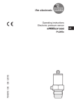
Operating instructions
Electronic pressure sensor
UK
704639 / 01 09 / 2010
PI16xx Contents
1 Preliminary note���������������������������������������������������������������������������������������������������3
1.1 Symbols used������������������������������������������������������������������������������������������������3
2 Safety instructions�����������������������������������������������������������������������������������������������3
3 Functions and features����������������������������������������������������������������������������������������4
3.1 Applications���������������������������������������������������������������������������������������������������4
4 Function���������������������������������������������������������������������������������������������������������������4
4.1 Processing of the measured signals��������������������������������������������������������������4
4.2 Pressure monitoring/ analogue function��������������������������������������������������������4
5 Installation�����������������������������������������������������������������������������������������������������������6
6 Electrical connection��������������������������������������������������������������������������������������������8
7 Operating and display elements��������������������������������������������������������������������������9
8 Menu������������������������������������������������������������������������������������������������������������������10
8.1 Menu structure���������������������������������������������������������������������������������������������10
8.2 Menu explanation ��������������������������������������������������������������������������������������� 11
9 Parameter setting����������������������������������������������������������������������������������������������12
9.1 Parameter setting general���������������������������������������������������������������������������12
9.2 Configuring the display (optional)����������������������������������������������������������������14
9.3 Setting the output signal������������������������������������������������������������������������������14
9.3.1 Setting the output function������������������������������������������������������������������14
9.3.2 Scaling the analogue value����������������������������������������������������������������15
9.4 User settings (optional)��������������������������������������������������������������������������������16
9.4.1 Zero-point calibration��������������������������������������������������������������������������16
9.4.2 Setting the damping for the analogue signal��������������������������������������16
9.5 Service functions�����������������������������������������������������������������������������������������16
9.5.1 Reading the min./max. values for the system pressure����������������������16
9.5.2 Reset all parameters to the factory setting�����������������������������������������16
10 Operation���������������������������������������������������������������������������������������������������������17
10.1 Read the set parameter values�����������������������������������������������������������������17
10.2 Fault indication������������������������������������������������������������������������������������������17
10.3 Cleaning of the filter cover�������������������������������������������������������������������������17
11 Scale drawing �������������������������������������������������������������������������������������������������18
2
12 Technical data��������������������������������������������������������������������������������������������������18
12.1 Setting ranges�������������������������������������������������������������������������������������������20
13 Factory setting�������������������������������������������������������������������������������������������������21
UK
1 Preliminary note
1.1 Symbols used
►
>
[…]
→
Instruction
Reaction, result
Designation of buttons, switches or indications
Cross-reference
Important note
Non-compliance can result in malfunctions or interference.
2 Safety instructions
• Read this ducument before installing the unit. Ensure that the product is suitable for your application without any restrictions.
• Non-adherence to the operating instructions or technical data can lead to
personal injury and/or damage to property.
• In all applications check compliance of the product materials (→ chapter 12
Technical data) with the media to be measured.
• For units with cULus approval and the scope of validity cULus → chapter 6
Electrical connection.
3
3 Functions and features
The pressure sensor detects the system pressure of machines and installations.
3.1 Applications
Type of pressure: relative pressure
Order no.
PI1693
PI1694
PI1695
PI1696
PI1689
PI1697
PI1698
PI1699
Measuring range
bar
-1...25
-1...10
-1...4
-0.124...2.5
mbar
5...100
-50...1 000
-12.4...250
-1 000...1 000
PSI
-14.4...362.7
-14.5...145
-14.5...58
-1.8...36.24
PSI
-0.073...1.45
-0.73...14.5
-0.18...3.62
-14.5...14.5
Permissible Bursting pressure
overload pressure
bar
PSI
bar
PSI
100
1 450
350
5 070
50
725
150
2 175
30
435
100
1 450
20
290
50
725
bar
PSI
bar
PSI
4
58
30
435
10
145
30
435
10
145
30
435
10
145
30
435
MPa = bar ÷ 10 / kPa = bar × 100
Static and dynamic overpressures exceeding the indicated overload pressure are to be avoided by taking appropriate measures.
The indicated bursting pressure must not be exceeded. Even if the bursting pressure is exceeded only for a short time, the unit can be destroyed.
NOTE: Risk of injury!
4 Function
4.1 Processing of the measured signals
• The unit displays the current system pressure.
• It generates 1 output signal according to the parameter setting.
OUT
analogue signal 4...20 mA (20...4 mA)
4.2 Pressure monitoring/ analogue function
The analogue signal can be set.
• [OU2] defines whether the set measuring range is provided as a 4...20 mA
signal ([OU2] = [I]) or a 20...4 mA signal ([OU2] = [InEG]).
4
Scaling can also be set by means of the teaching process or by entering a value
for the ASP and AEP parameters.
• By teaching the analogue start point (tASP) or setting the parameter ASP you
define the measured value at which the output signal is 4 mA (20 mA at [InEG]).
• By teaching the analogue end point (tAEP) or setting the parameter AEP you
define the measured value at which the output signal is 20 mA (4 mA at [InEG]).
Minimum distance between [ASP] and [AEP] = 25 % of the final value of the measuring range (turn down 1:4).
Factory setting
Measuring range scaled
UK
P = system pressure, MAW = initial value of the measuring range, MEW = final value of
the measuring range
1 : [OU2] = [I]; 2 : [OU2] = [InEG]
The output signal is between 4 and 20 mA ([OU2] = [I]) or between 20 and 4 mA
([OU2] = [InEG]). It is also indicated:
• System pressure above the measuring range:
-- output signal > 20 mA if [OU2] = [I].
-- output signal between 4 and 3.8 mA if [OU2] = [InEG].
• System pressure below the measuring range:
-- output signal between 4 and 3,8 mA if [OU2] = [I].
-- output signal > 20 mA if [OU2] = [InEG].
5
5 Installation
Ensure that no pressure is applied to the installation while mounting or
removing the sensor. Please note: Display „0%“ does not mean that the
system is free of pressure!
Horizontal mounting recommended for high medium temperatures.
►► Screw the sensor into a G 1 process fitting.
►► Tighten the sensor with a spanner.
Tightening torque: 20 Nm.
A = freely rotatable housing
The unit is adaptable for various G 1 process fittings. G 1 process adapters to be
ordered separately as accessories.
6
Mounting
1
3
UK
2
►► Screw the unit into the adapter (A) until it is hand-tight (fig. 1). Do not damage
the sealing chamfers.
►► Clamp sensor and adapter into a clamping device (B); (fig. 2). Tighten the
clamping device only slightly so that the adapter does not warp.
►► Tighten the sensor using a spanner .
Tightening torque: 20 Nm.
►► Fix the unit + adapter to the process connection by means of a coupling nut, a
clamp flange or the like (C); (fig 3).
NOTE: A guarantee for a long-term stable sealing of the metal seal is only valid for
once-only mounting.
Welding adapter
►► First weld the adapter, then mount the sensor. Follow the instructions included
with the adapter.
7
6 Electrical connection
The unit must be connected by a qualified electrician.
The national and international regulations for the installation of electrical
equipment must be adhered to.
Voltage supply to EN50178, SELV, PELV.
For units with cULus approval and the scope of validity cULus: The device shall
be supplied from an isolating transformer having a secondary Listed fuse rated as
noted in the following table.
Overcurrent protection
Control-circuit wire size
AWG
(mm2)
26
(0.13)
24
(0.20)
22
(0.32)
20
(0.52)
18
(0.82)
16
(1.3)
Maximum protective device rating
Ampere
1
2
3
5
7
10
The Sensor shall be connected only by using any R/C (CYJV2) cord, having
suitable ratings.
►► Disconnect power.
►► Connect the unit as follows:
Normal operation
Programming operation
Pin 1
Ub+
Pin 3
UbPin 4 (P)
P = communication via EPS / FDT interface
Pin 2 (OUT2) analogue output for system pressure
Core colours of ifm sockets:
1 = BN (brown), 2 = WH (white), 3 = BU (blue), 4 = BK (black)
8
7 Operating and display elements
UK
1 to 8: Indicator LEDs
-- LED 1 to LED 6 = system pressure in unit of measurement as indicated on the label.
LEDs 5 to 6 not used for units with 4 adjustable units of measurement.
-- LED 7 not used.
-- LED 8 not used.
9: Alphanumeric display, 4 digits
-- Indication of the current system pressure.
-- Indication of the parameters and parameter values.
10: Set pushbutton
-- Setting of the parameter values (scrolling by holding pressed, incremental by pressing
briefly).
11: Mode/Enter pushbutton
-- Selection of the parameters and acknowledgement of the parameter values.
9
8 Menu
8.1 Menu structure
10
8.2 Menu explanation
OU2
tCOF
tASP
tAEP
EF
Uni
SELd
ASP
AEP
HI
LO
COF
dAA
diS
rES
Output function for OUT2:
•Analogue signal for the current system pressure: 4...20 mA [I] or 20...4 mA
[InEG].
Teaching zero-point calibration.
Teaching analogue start point for the system pressure: set value at which
4 mA are output (20 mA on [OU2] = [InEG]).
Teaching analogue end point for the system pressure: set value at which
20 mA are output (4 mA on [OU2] = [InEG]).
UK
Extended functions / Opening menu level 2.
Standard unit of measurement for the system pressure.
Display mode:
•Pressure in the unit set in [Uni].
•Pressure in % of the set scaling of the analogue output.
Analogue start point for the system pressure: measured value at which 4 mA
are output (20 mA on [OU2] = [InEG]).
Analogue end point for the system pressure: measured value at which 20 mA
are output (4 mA on [OU2] = [InEG]).
Maximum value memory for the system pressure.
Minimum value memory for the system pressure.
Zero point calibration.
Damping for the analogue output.
Update rate and orientation of the display.
Restore the factory setting.
11
9 Parameter setting
During the parameter setting process the unit remains in the operating mode.
It continues its monitoring function with the existing parameters until parameter
setting has been terminated.
9.1 Parameter setting general
Each parameter setting requires 3 steps:
1
Selecting parameter
►► Press [Mode/Enter] until the requested parameter is displayed.
2
Setting the parameter value
►► Press [Set] and keep the buton
pressed.
>> Current setting value of the parameter bit flashes for 5 s.
>> After 5 s: Setting value is changed:
incremental by pressing briefly or
scrolling by holding pressed.
The numerical values are incremented continuously. If the value is to be reduced: Let
the display move to the maximum setting value. Then the cycle starts again at the
minimum setting value.
3 Acknowledge parameter value
►► Press [Mode/Enter] briefly.
>> The parameter is displayed again.
The new setting value is stored.
Set more parameters
►► Start again with step 1.
Finishing parameter setting
►► Press [Mode/Enter] several times until the current measured value is displayed or wait
for 15 s.
>> The unit returns to the operating mode.
12
• Changing from menu level 1 to menu level 2:
►► Press [Mode/Enter] until [EF] is
displayed.
►► Press [Set] briefly.
>> The first parameter of the submenu is
displayed (here: [Uni]).
If menu level 2 is protected by an access
code, „Cod1“ flashes in the display.
►► Press [Set] and keep it pressed until
the valid code no. is displayed.
►► Press [Mode/Enter] briefly.
Delivery by ifm electronic: no access
restriction.
UK
• Locking / unlocking
The unit can be locked electronically to prevent unintentional wrong settings.
►► Ensure that the unit is in the normal
operating mode.
►► Press [Mode/Enter] + [Set] for 10 s.
>> [Loc] is displayed.
During operation: [Loc] is displayed briefly when you try to change parameter values.
For unlocking:
►► Press [Mode/Enter] + [Set] for 10 s.
>> [uLoc] is displayed.
On delivery: Unlocked.
• Timeout:
If no button is pressed for 15 s while the parameters are being set, the unit returns to
the operating mode with unchanged values.
13
9.2 Configuring the display (optional)
►► Select [Uni] and set the unit of measurement:
-- [bAr], [mbAr],
-- [MPA], [kPA],
-- [PSI],
-- [InHO] (only PI1689, PI1696, PI1697, PI1698, PI1699),
-- [mWS] (only PI1696, PI1697, PI1699),
-- [mmWS] (only PI1689 and PI1698).
►► Select [SELd] and set the display mode:
-- [P]: Pressure in the unit set in Uni.
-- [P%]: percentage value (pressure in % of the set scaling of the
analogue output. The following applies: 0% = ASP value; 100% = AEP
value).
NOTE: Display „0%“ does not mean that the system is free of pressure.
►► Select [diS] and set update rate and orientation of the display:
-- [d1]: Update of the measured value every 50 ms.
-- [d2]: Update of the measured value every 200 ms.
-- [d3]: Update of the measured value every 600 ms.
-- [rd1], [rd2], [rd3]: Display like d1, d2, d3; rotated by 180°.
-- [OFF]: The display is deactivated in the operating mode. If one of the
buttons is pressed, the current measured value is displayed for 15 s.
Another press of the Mode/Enter button opens the Display mode. The
LEDs remain active even if the display is deactivated.
9.3 Setting the output signal
9.3.1 Setting the output function
►► Select [OU2] and set the anologue function:
-- [I] = current signal proportional to the pressure 4…20 mA,
-- [InEG] = current signal proportional to the pressure 20…4 mA.
14
9.3.2 Scaling the analogue value
►► Set the requested minimum pressure in the system.
►► Press [Mode/Enter] until [tASP] is displayed.
►► Press [Set] and keep the buton pressed.
>> The currently set value flashes.
►► Release [Set] when the display stops flashing.
>> The new set value is displayed.
►► Press [Mode/Enter] briefly.
>> The current system pressure is defined to be the start value for the
analogue signal.
►► Set the requested maximum pressure in the system.
UK
►► Press [Mode/Enter] until [tAEP] is displayed.
►► Press [Set] and keep the buton pressed.
>> The currently set value flashes.
►► Release [Set] when the display stops flashing.
>> The new set value is displayed.
►► Press [Mode/Enter] briefly.
>> The current system pressure is defined to be the end value for the
analogue signal.
ASP / AEP can only be taught within defined limits (→ 12.1 setting ranges). If the teaching
process is carried out at an invalid pressure, [UL] or [OL] is displayed. After acknowledgement by [Mode/Enter], [Err] flashes, the ASP value / AEP value is not changed.
As an alternative:
►► Select [ASP] and set measured value at which 4 mA are output (20 mA
at [OU2] = [InEG]).
►► Select [AEP] and set measured value at which 20 mA are output (4 mA
at [OU2] = [InEG]).
Minimum distance between ASP and AEP = 25 % of the final value of the
measuring range (scaling factor 1:4).
15
9.4 User settings (optional)
9.4.1 Zero-point calibration
►► Select [COF] and set a value between -5% and 5% of the final value of
the measuring range. The internal measured value “0” is shifted by this
amount.
As an alternative:
Automatic adaptation offset (setting range 0 bar ±5%); e.g. in the event of a
deviation of the mounting location of the sensor and the zero point level for
level measurement.
►► Make sure that no pressure is applied to the system.
►► Press [Mode/Enter] until [tCOF] is displayed.
►► Press [Set] and keep the buton pressed.
>> The current offset value (in %) briefly flashes, then the current system
pressure (in the selected display unit) is displayed.
►► Release [Set].
►► Press [Mode/Enter] briefly to confirm the new offset value.
9.4.2 Setting the damping for the analogue signal
►► Select [dAA] and set value between 0.1 and 100.0 s (at 0.0 = [dAA] is
not active).
dAA value = response time between pressure change and change of the
analogue signal in seconds.
9.5 Service functions
9.5.1 Reading the min./max. values for the system pressure
►► Select [HI] or [LO], press [Set] briefly.
[HI] = maximum value, [LO] = minimum value.
Delete memory:
►► Select [HI] or [LO].
►► Press [SET] until [----] is displayed.
►► Press [MODE/ENTER] briefly.
9.5.2 Reset all parameters to the factory setting
►► Select [rES]
►► Press [SET] until [----] is displayed.
►► Press [MODE/ENTER] briefly.
It makes sense to note down your own settings before executing the function (→ 13 Factory preset).
16
10 Operation
After power on of the supply voltage the unit is in the Run mode (= normal operation). It carries out its measurement and evaluation functions and generates output
signals according to the set parameters.
Operating indicators → chapter 7 Operating and display elements.
10.1 Read the set parameter values
►► Press [Mode/Enter] until the requested parameter is displayed.
►► Press [Set] briefly.
>> The unit displays the corresponding parameter value for about 15 s. After
another 15 s the unit returns to the Run mode.
UK
10.2 Fault indication
[OL]
[UL]
[Err]
Overload pressure (measuring range exceeded).
Underpressure range (measuring range below the minimum value).
Internal fault, invalid input (indicated even if the display is deactivated).
10.3 Cleaning of the filter cover
If viscous and residues producing
media clog the filter cover of the sensor (and thus reduce the measuring
accuracy slightly), you can clean it.
►► Unscrew the filter cover (B) (use a
pair of pliers with plastic-covered
jaws for this).
►► Clean the cover thoroughly.
The vent (A) should only be cleaned by skilled personnel and with utmost care.
Possible medium residues must not be compressed and pressed into the vent.
This could clog the filter system and reduce the measuring accuracy of the
sensor.
►► Screw the filter cover again tightly.
17
11 Scale drawing
Dimensions are in millimeters
1: display
2: LED’s
3: programming button
12 Technical data
Operating voltage [V]............................................................................................ 20...32 DC
Reverse polarity / overload protection, integrated watchdog
Power-on delay time [s].................................................................................................... 0.5
Analogue output ............................................................................... 4...20 mA / 20...4 mA
Max. load current output [Ω] ........................................................................................... 300
Switch-on peak current.................................................................................. 60 mA (30 ms)
Step response time analogue output [ms] ........................................................................ 40
18
Accuracy / deviation (in % of the span)1)
Characteristics deviation (linearity. incl. hysteresis and repeatability)2)
Linearity
Hysteresis
Repeatability (with temperature fluctuations < 10 K)
Long-term stability (in % of the span per year)
PI169x
PI1689
< ± 0.2
< ± 0.5
< ± 0.15
< ± 0.15
< ± 0.1
< ± 0.1
< ± 0.15
< ± 0.15
< ± 0.1
< ± 0.1
- Temperature coefficient (TC) in the compensated temperature range 0 ... 70°C (in % of
the span per 10 K)
PI169x
PI1689
Greatest TC of the zero point
< ± 0.05 < ± 0.1
Greatest TC of the span
< ± 0.15 < ± 0.2
UK
Material (wetted parts)
.................................... stainless steel 316L / 1.4435, surface characteristics: Ra 0.4 / Rz 4
ceramics (99.9 % Al2 O3); PTFE;
Housing materials
......... stainless steel 316L / 1.4404; PC (Makrolon); PBT (Pocan); PEI; FPM (Viton); PTFE
Protection ........................................................................................................IP 67 / IP 69K
Protection class...................................................................................................................III
Insulation resistance [MΩ]..........................................................................> 100 (500 V DC)
Shock resistance [g]................................................................ 50 (DIN / IEC 68-2-27, 11ms)
Vibration resistance [g].................................................. 20 (DIN / IEC 68-2-6, 10 - 2000 Hz)
Switching cycles min............................................................................................ 100 million
Operating temperature [°C]................................................................................... -25 ... +80
Medium temperature [°C]................................................................. -25...125 (145 max. 1h)
Storage temperature [°C]...................................................................................... -40...+100
EMCEN 61000-4-2 ESD:.........................................................................................4 / 8 KV
EN 61000-4-3 HF radiated:............................................................................... 10 V/m
EN 61000-4-4 Burst:.............................................................................................2 KV
EN 61000-4-5 Surge: ...................................................................................0.5 / 1 KV
EN 61000-4-6 HF conducted:............................................................................... 10 V
1)
all indications are referred to a turn down of 1:1
2)
limit value setting to DIN 16086
19
12.1 Setting ranges
PI1689
ASP
mbar
kPa
inH2O
PI1698
PI1697
PI1696
PI1695
PI1694
PI1693
mmWS
bar
PSI
MPa
bar
PSI
MPa
bar
PSI
kPa
bar
PSI
kPa
inH2O
mWS
mbar
PSI
kPa
inH2O
mWS
mbar
kPa
inH2O
mmWS
ΔP = increments
20
min
5.0
-0.50
-2.00
-51
-1.00
-14.4
-0.100
-1.00
-14.5
-0.100
-1.000
-14.50
-100.0
-0.124
-1.80
-12.4
-50
-1.26
-50
-0.73
-5.0
-20.0
-0.51
-12.4
-1.24
-5.0
-126
AEP
max
75.0
7.50
30.12
765
18.74
271.8
1.874
7.50
108.7
0.750
3.000
43.50
300.0
1.880
27.27
188.0
755
19.17
750
10.88
75.0
301.2
7.65
187.4
18.74
75.3
1912
min
20.0
2.00
8.04
204
5.24
76.2
0.524
1.50
21.8
0.150
0.000
0.00
0.0
0.500
7.26
50.0
201
5.10
200
2.90
20.0
80.4
2.04
50.0
5.00
20.1
510
max
100.0
10.00
40.16
1020
25.00
362.7
2.500
10.00
145.0
1.000
4.000
58.00
400.0
2.500
36.27
250.0
1004
25.49
1000
14.50
100.0
401.6
10.20
250.0
25.0
100.4
2250
ΔP
0.1
0.01
0.04
1
0.02
0.3
0.002
0.01
0.1
0.001
0.005
0.05
0.5
0.002
0.03
0.2
1
0.01
1
0.01
0.1
0.4
0.01
0.2
0.02
0.1
2
ASP
PI1699
mbar
PSI
kPa
inH2O
mWS
ΔP = increments
min
-1000
-14.50
-100.0
-401
-10.20
AEP
max
500
7.25
50.0
201
5.10
min
-500
-7.25
-50.0
-201
-5.10
max
1000
14.50
100.0
401
10.20
ΔP
1
0.05
0.1
1
0.01
UK
13 Factory setting
OU2
ASP / tASP
AEP / tAEP
COF / tCOF
dAA
Uni
SELd
dis
Factory setting
I
0% VMR*
100% VMR*
0.0
0.1
bAr / mbAr
P
d2
User setting
* = the indicated percentage of the final value of the measuring range (VMR) of the
corresponding sensor in bar / mbar is set.
More information at www.ifm.com
21