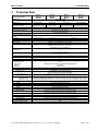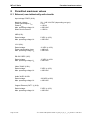
1
Operating instructions MT-xx7 Series Panel PC MT-4x7 Remote HMI Thin Client MT-5x7 Remote HMI KVM MT-6x7 R. STAHL HMI Systems GmbH Im Gewerbegebiet Pesch 14 D-50767 Köln HW-Rev. MT-xx7: Doc.No.: Operating Instructions Version: Issue date: 01.00.00 60000189 01.01.00 10.09.2012 MT-xx7 Serie Publisher Publisher Publisher and copyright holder: R. STAHL HMI Systems GmbH Im Gewerbegebiet Pesch 14 D-50767 Köln Registered place of business: Registration Court: USt.-Id.-Nr. / VAT number: Cologne AG Cologne, HRB 30512 DE 812 454 820 Telephone: (switchboard) (Hotline) Telefax: E-mail:[email protected] (Hotline) +49/(0)221/ 5 98 08 - 200 - 59 - 260 [email protected] All rights reserved. This document may not be reproduced in whole or in part except with the written consent of the publisher. We reserve the right to make technical changes without notice. This documentation has been produced and checked with due care. R. STAHL HMI Systems GmbH shall, however, not accept liability for any mistakes in this and all other documents. Any warranty claims are limited to the right to demand amendments. Liability for any damage that might result from the contents of these instructions or all other documentation is limited to clear cases of premeditation. We reserve the right to change our products and their specifications at any time, provided it is in the interest of technical progress. The information in the current manual (online or on CD) or in the operating instructions included with the operator interface applies. Trademarks The terms and names used in this document are registered trademarks and / or products of the companies in question. WINDOWS ® 95/98/2000/NT/ME/XP/Vista/7/Server are registered trademarks of MICROSOFT Corporation, USA. Copyright © 2012 by R.STAHL HMI Systems GmbH. Subject to alterations. Page 2 of 28 R. STAHL HMI Systems GmbH / OI_MT_xx7_en_V_1_01_00.docx / 10.09.2012 MT-xx7 Serie Table of contents Table of contents 1 1.1 1.2 2 2.1 2.2 2.3 3 4 5 5.1 6 7 7.1 8 8.1 8.2 8.3 9 9.1 9.2 9.3 10 10.1 10.2 10.3 10.4 11 11.1 11.2 12 12.1 12.2 13 14 14.1 15 15.1.1 16 17 17.1 17.1.1 Description Publisher Table of contents Preface General Notes Technical progress Device function Panel PC MT-4x7 Remote HMI Thin Client MT-5x7 Remote HMI KVM MT-6x7 Technical Data Conformity to standards Certificates ATEX Marking Power supply Operator interfaces Permitted maximum values External, non-intrinsically safe circuits External inherently safe optical interface External intrinsically safe circuits Type code Panel PC MT-4x7 Remote HMI Thin Client MT-5x7 Remote HMI KVM MT-6x7 Safety information General Safety Information Installation safety information Safety information for operation Special conditions Assembly and disassembly General information Cut-out MT-xx7 Operation General information Connections Maintenance Troubleshooting Repairs / hazardous substances Disposal ROHS directive 2002/95/EC Trademarks Front panel resistance Materials Material properties R. STAHL HMI Systems GmbH / OI_MT_xx7_en_V_1_01_00.docx / 10.09.2012 Page 2 3 5 5 5 6 6 6 6 7 8 9 9 9 9 9 10 10 11 11 12 12 13 14 15 15 15 17 17 18 18 18 18 18 19 21 21 21 21 21 21 22 22 22 Page 3 of 28 MT-xx7 Serie 17.1.2 18 19 Page 4 of 28 Table of contents Touch membrane (polyester) Declaration of EC conformity Release notes 22 25 26 R. STAHL HMI Systems GmbH / OI_MT_xx7_en_V_1_01_00.docx / 10.09.2012 MT-xx7 Serie 1 Preface Preface These Operating Instructions contain all aspects relevant to explosion protection for the MT-xx7 operator interfaces (Panel PC and Remote HMI series). They also contain information on the connection and installation of these devices. Please also refer to additional documentation included in the delivery, such as the EC type examination certificate and the hardware manual, which contain further important information. For the correct operation of all associated components please note, in addition to these operating instructions, all other operating instructions enclosed in this delivery as well as the operating instructions of the additional equipment to be connected. Please also note that all certificates for the operator interfaces are included in a separate document. 1.1 General Notes Please read the entire operating instructions before assembling the product. In case of doubt the German original shall apply. We assume no liability for any typographical errors in these operating instructions. In case of questions or suggestions, please don't hesitate to contact R. STAHL HMI Systems GmbH. 1.2 Technical progress Alterations require the written consent of R. STAHL HMI Systems GmbH. The manufacturer reserves the right to adjust technical data to be in line with technical progress without any specific announcements. R. STAHL HMI Systems GmbH / OI_MT_xx7_en_V_1_01_00.docx / 10.09.2012 Page 5 of 28 MT-xx7 Serie 2 Device function Device function The MT-xx7 operator interfaces are explosion-protected equipment for installation in hazardous areas and can be operated in zones 2 and 22 with interfaces for zones 0/1/2 and 20/21/22. The devices are connected to a communication system via the serial interfaces (RS-232, Ethernet) located in their connection box at the rear. The connection box also contains the USB interfaces for the connection of various peripheral devices. Furthermore, the interfaces for keyboard, mouse, video and audio signals are also located here. 2.1 Panel PC MT-4x7 The MT-4x7 operator interfaces are intelligent display and operating devices which can run any software and are thus easy to operate. The devices are fitted with powerful processors and are thus able to process even large applications on-site. The devices have a back-up and recovery system which can be used to save complete images and load them onto new Panel PCs without requiring specific IT skills. The X13 interface is provided for this purpose. 2.2 Remote HMI Thin Client MT-5x7 The Remote HMIs of the MT-5x7 series can be integrated into modern networks as Thin Clients or with a KVM box via KVM-over-IP. Digital Ethernet technology is used for the data transfer between KVM box and Remote System. Up to four Remote HMIs can access one KVM box with one software license, thus costeffectively communicating with several PCs - for example, when monitoring the production process and simultaneously applying Condition Monitoring. Multi-monitoring with several on-site terminals can as easily be implemented as the application as Thin Client in a server environment with virtual work stations. 2.3 Remote HMI KVM MT-6x7 The KVM Classic transfer technology is used for the point-to-point connection between a PC and an MT-6x7 Remote HMI terminal. There are two versions (DVI1 and DVI2) of this transfer technology that have slightly different functionality. Page 6 of 28 R. STAHL HMI Systems GmbH / OI_MT_xx7_en_V_1_01_00.docx / 10.09.2012 MT-xx7 Serie 3 Technical Data Technical Data Function / Equipment MT-457 MT-557 MT-657 MT-467 MT-567 MT-667 Display type Display size Resolution in pixels Format Display Touch Screen (optional) Backlight Service life (MTBF) of backlight at 20°C Brightness Contrast Additional keyboard (optional) Power supply Connections Voltage supply Power consumption [A] Power Recommended fuses Max. operating voltage Um only for MT-4x7 and MT-5x7 Real-time clock Data buffer Battery Capacitor Interfaces Ethernet Copper (Tx) Optical fibre (Fx) Cable type Optical fibre MM Optical fibre SM USB USB Serial Video Audio Data cable lengths Optical fibre MM Optical fibre SM Copper (Tx) for DVI1 CAT for DVI2 CAT Enclosure Enclosure protection type 48 cm (19") SXGA 1280 x 1024 5:4 MT-477 MT-577 MT-677 TFT Color display 16.7 million colours 56 cm (22") 61 cm (24") WSXGA+ Full HD 1920 x 1080 1680 x 1050 16:10 16:9 Glass Membrane or glass surface 5-wire analogue resistive LED background lighting MT-487 MT-587 MT-687 61 cm (24"WU) WUXGA 1920 x 1200 16:10 typically 50,000 h 350 cd/m² 250 cd/m² 300 cd/m² 1000 : 1 107 keys with integrated trackball / joystick / mouse pad or touch pad Directly in the integrated connection box via control spring terminals, green flexible cable up to 2.5 mm² (AWG 16) fixed cable up to 4 mm² (AWG 14) 24 VDC or 100 - 240 VAC, 50 - 60 Hz at 24 VDC = max. 3 A at 100 - 240 VAC = max. 1 A typically 35 W / max. 150 W (typically 119 BTU / max. 510 BTU) 5 AT 250 VAC Yes Lithium battery and capacitor buffered, maintenance-free > 5 years at least 4 days Either Tx or Fx 10/100BaseTx, 10/100 Mbit (Ex-nA) only for MT-6x7 direct connection Gigabit 100BaseFx, 100 Mbit, intrinsically safe (Ex op is) only for MT-6x7 direct connection Multi-mode optical fibre cable (50 µm core cross section and 125 µm external cross section) Single-mode optical fibre cable (9 µm core cross section and 125 µm external cross section) 2x Ex-ia; 1x Ex-nA For keyboard and mouse (Ex-ia) RS-232, (Ex-nA) FBAS (Ex-nA) Line In/Out interface (Ex-nA) up to 500 m (1,640 ft) via 50/125 μm optical fibre cable, up to 300 m (985 ft) via 62.5/125 μm optical fibre cable up to 10,000 m (33,000 ft) via 9/125 μm optical fibre cable up to 100 m (330 ft) via CAT7 installation cable AWG 22 up to 140 m (460 ft) via CAT7 installation cable AWG 22 up to 500 m (1,640 ft) via CAT7 installation cable AWG 22 Stahl IP66 R. STAHL HMI Systems GmbH / OI_MT_xx7_en_V_1_01_00.docx / 10.09.2012 Page 7 of 28 MT-xx7 Serie Conformity to standards Permitted ambient temperature - 30°C … + 60°C range Operating temperature range Cold start temperature - 10°C … + 50°C Operation - 20°C … + 60°C Permanent operation - 20°C … + 50°C Operation with heater * - 30°C … + 50°C Short-term operation - 30°C … + 60°C for a maximum of 5 h Storage temperature range - 30°C … + 70°C Operating temperature range for DVI1 Cold start temperature + 5°C … + 40°C Operation + 5°C … + 40°C Permanent operation + 5°C … + 40°C Operation with heater * + 5°C … + 40°C Storage temperature range - 20°C … + 70°C * Comment The heater used must be of such a design that the temperature inside the operator interface's housing does not fall below -20°C (-30°C only at the front)! Heat dissipation about 40% via the front plate and 60% via the enclosure Relative humidity 10 to 90% at +40°C, non-condensing for DVI1 20 to 80% at 40°C, non-condensing Dimensions [mm] (inch) Front (w x h) 660 x 475 (25.98” x 18.70”) Cut-out (w x h) (+/- 0.5) (0.002") 615 x 435 (24.21” x 17.13”) Depth of cut-out 110 (4.33") Wall thickness ≤ 5 (0.02") Mounting position: vertical or horizontal Weight [kg] (lb) Operator interface 16.00 (35.3 lb) 4 Conformity to standards The MT-xx7 operator interfaces comply with the following standards and directives: Standard Classification directive 94/9 EC Initial certification EN 60079-0 : 2009 General requirements EN 60079-11 : 2007 Intrinsic safety "i" EN 60079-15 : 2010 Type of protection "n" EN 60079-28 : 2007 Optical radiation EN 60079-31 : 2009 Protected by enclosures "tD" (dust) EN 61241-11 : 2006 Electromagnetic compatibility directive 2004/108 EC EN 61000-6-2 : 2006 Interference resistance EN 61000-6-4 : 2007 Interference emission Low voltage directive directive 2006/95 EC EN 50178 1997 : Fitting power plants with electronic equipment EN 61010-1 : 2001+ General requirements Page 8 of 28 R. STAHL HMI Systems GmbH / OI_MT_xx7_en_V_1_01_00.docx / 10.09.2012 MT-xx7 Serie 5 Certificates Certificates The MT-xx7 operator interfaces are certified for installation in the following areas: according to ATEX Directive 94/9/EC for installation in zones 2 and 22 5.1 ATEX The ATEX certificates are listed under the following certification numbers: Certificate number for MT-xx7: 6 BVS 12 ATEX E 033 X Marking Manufacturer R. STAHL HMI Systems GmbH Type code MT-xx7 CE classification: c 0158 Testing authority and certificate number: BVS 12 ATEX E 033 X Ex classification: ATEX guideline 94/9/EC 7 7.1 e II 3(1) G Ex nA nR [ia op is Ga] IIC T4 Gc II 3(1) D Ex tc IIIC [ia op is Da] IP66 T110°C Dc Power supply Operator interfaces Power supply: Power consumption: 24 VDC or 100 – 240 VAC, 50 – 60 Hz at 24 VDC max. 3 A at 100 - 240 VAC max. 1 A R. STAHL HMI Systems GmbH / OI_MT_xx7_en_V_1_01_00.docx / 10.09.2012 Page 9 of 28 MT-xx7 Serie 8 Permitted maximum values Permitted maximum values 8.1 External, non-intrinsically safe circuits Input voltage "PWR" (X10): Nominal voltage: Power consumption Imax Power Pmax Max. operating voltage Um Short-circuit current IK 20 ...240 V AC/DC (depending on type) ≤5A ≤ 150 W ≤ 250 VAC ≤ 1500 A USB (X13): Rated voltage Max. operating voltage Um 5 VDC (± 10%) ≤ 250 VAC 12 V (X14): Rated voltage Power consumption Imax Max. operating voltage Um 12 VDC (± 10%) ≤ 400 mA ≤ 250 VAC RS-232 "SER" (X97): Rated voltage Max. operating voltage Um 15 VDC (± 10%) ≤ 250 VAC Video "CAM" (X101): Rated voltage Max. operating voltage Um 5 VDC (± 10%) ≤ 250 VAC Audio "AUD" (X105): Rated voltage Max. operating voltage Um 100 VDC (±10%) ≤ 250 VAC Copper Ethernet (CAT7 1) (X16): Rated voltage Max. operating voltage Um Page 10 of 28 5 VDC (± 10%) ≤ 250 VAC R. STAHL HMI Systems GmbH / OI_MT_xx7_en_V_1_01_00.docx / 10.09.2012 MT-xx7 Serie 8.2 Permitted maximum values External inherently safe optical interface Ethernet optical fiber (FO 1) (X18) Multi-mode Wavelength Radiant power max. radiant power: 850 nm 0.22 mW 35 mW Single mode Wavelength Radiant power max. radiant power: 1310 nm 0.22 mW 35 mW 8.3 External intrinsically safe circuits Keyboard (X11) The maximum values are: Ui = 5.5 Ii = 3 Pi = 2 Ci = negligible Li = negligible C A W F mH Uo lo Po Co Lo = = = = = 5.5 309 629 50 40 C mA mW F H C A W F mH Uo lo Po Co Lo = = = = = 5.5 309 629 50 40 C mA mW F H C A W F mH Uo lo Po Co Lo = = = = = 5.5 309 629 50 40 C mA mW F H C A W F mH Uo lo Po Co Lo = = = = = 5.5 309 629 50 40 C mA mW F H Pointer device (X12): The maximum values are: Ui = 5.5 Ii = 3 Pi = 2 Ci = negligible Li = negligible USB1i (X24): The maximum values are: Ui = 5.5 Ii = 3 Pi = 2 Ci = negligible Li = negligible USB2i (X25): The maximum values are: Ui = 5.5 Ii = 3 Pi = 2 Ci = negligible Li = negligible R. STAHL HMI Systems GmbH / OI_MT_xx7_en_V_1_01_00.docx / 10.09.2012 Page 11 of 28 MT-xx7 Serie 9 9.1 Type code Type code Panel PC MT-4x7 MT-4x7-aa-bb-cc-dd-ee-ff-gg Front design Power supply Data memory Main memory Touch screen Display type Ethernet interface 457 / 467 / 477 / 487 Product type: Product key structure MT-4x7-FX-MM-bb-cc-dd-ee-ff-gg MT-4x7-TX-bb-cc-dd-ee-ff-gg MT-4x7-aa-TFT-cc-dd-ee-ff-gg MT-4x7-aa-bb-T-dd-ee-ff-gg MT-4x7-aa-bb-TG-dd-ee-ff-gg MT-4x7-aa-bb-cc-R1-ee-ff-gg MT-4x7-aa-bb-cc-R2-ee-ff-gg MT-4x7-aa-bb-cc-dd-4GB-ff-gg MT-4x7-aa-bb-cc-dd-16GB-ff-gg MT-4x7-aa-bb-cc-dd-100GB-ff-gg MT-4x7-aa-bb-cc-dd-ee-AC-gg MT-4x7-aa-bb-cc-dd-ee-DC-gg MT-4x7-aa-bb-cc-dd-ee-ff-AL MT-4x7-aa-bb-cc-dd-ee-ff-VA MT-4x7-aa-bb-cc-dd-ee-ff-RM Page 12 of 28 Description Type with Optical fiber Ethernet interface100BaseFx (Ex op is), multi-mode Copper Ethernet interface 10/100BaseTx (Ex-nA) TFT display (standard) Touch screen (foil) Touch screen glass Working memory 1 GB Working memory 2 GB 4 GB Solid State Drive 16 GB Solid State Drive 100 GB hard disk (internal) Power supply 100 - 240 VAC, 50 - 60 Hz Power supply 24 VDC Aluminium front plate Front plate stainless steel Rear end module R. STAHL HMI Systems GmbH / OI_MT_xx7_en_V_1_01_00.docx / 10.09.2012 MT-xx7 Serie 9.2 Type code Remote HMI Thin Client MT-5x7 MT-5x7-aa-bb-cc-dd-ee Front design Power supply Touch screen Display type Ethernet interface 557 / 567 / 577 / 587 Product type: Product key structure MT-5x7-FX-MM-bb-cc-dd-ee MT-5x7-TX-bb-cc-dd-ee MT-5x7-aa-TFT-cc-dd-ee MT-5x7-aa-bb-T-dd-ee MT-5x7-aa-bb-TG-dd-ee MT-5x7-aa-bb-cc-AC-ee MT-5x7-aa-bb-cc-DC-ee MT-5x7-aa-bb-cc-dd-AL MT-5x7-aa-bb-cc-dd-VA MT-5x7-aa-bb-cc-dd-RM Description Type with Optical fiber Ethernet interface100BaseFx (Ex op is), multi-mode Copper Ethernet interface 10/100BaseTx (Ex-nA) TFT display (standard) Touch screen (foil) Touch screen glass Power supply 100 - 240 VAC, 50 - 60 Hz Power supply 24 VDC Aluminium front plate Front plate stainless steel Rear end module R. STAHL HMI Systems GmbH / OI_MT_xx7_en_V_1_01_00.docx / 10.09.2012 Page 13 of 28 MT-xx7 Serie 9.3 Type code Remote HMI KVM MT-6x7 MT-6x7-aa-bb-cc-dd-ee Front design Power supply Touch screen Display type Transfer technology 657 / 667 / 677 / 687 Product type: Product key structure MT-6x7-DVI1-CAT-bb-cc-dd-ee MT-6x7-DVI1-MM-bb-cc-dd-ee MT-6x7-DVI1-SM-bb-cc-dd-ee MT-6x7-DVI2-CAT-bb-cc-dd-ee MT-6x7-aa-TFT-cc-dd-ee MT-6x7-aa-bb-T-dd-ee MT-6x7-aa-bb-TG-dd-ee MT-6x7-aa-bb-cc-AC-ee MT-6x7-aa-bb-cc-DC-ee MT-6x7-aa-bb-cc-dd-AL MT-6x7-aa-bb-cc-dd-VA MT-6x7-aa-bb-cc-dd-RM Page 14 of 28 Description Type with DVI1 KVM, with direct copper connection Gigabit (Ex-nA) DVI1 KVM, with direct optical fibre connection (Ex op is), multi-mode DVI1 KVM, with direct optical fibre connection (Ex op is), single-mode DVI2 DVI, with direct copper connection Gigabit (Ex-nA) TFT display (standard) Touch screen (foil) Touch screen glass Power supply 100 - 240 VAC, 50 - 60 Hz Power supply 24 VDC Aluminium front plate Front plate stainless steel Rear end module R. STAHL HMI Systems GmbH / OI_MT_xx7_en_V_1_01_00.docx / 10.09.2012 MT-xx7 Serie Safety information 10 Safety information 10.1 General Safety Information All relevant accident prevention regulations and the rules for electric installations have to be observed during installation, maintenace and operations. All persons involved in installation, commission, maintenance and repairs of this device and its accessories must be qualified accordingly and must have familiarised themselves with this manual and any associated documentation. In case of non-compliance or contravention of the above explosion-protection is no longer guaranteed and all warranty claims shall be null and void. National safety and accident prevention rules apply. Use the device for its intended purpose only. No changes to the device are permitted. The enclosure may only be opened by R. STAHL HMI Systems GmbH. The first four digits of the serial number on the type plate stand for the year of manufacture. 10.2 Installation safety information The national assembly and installation rules and the generally accepted technical rules must be observed. The device and its accessories must be connected and operated according to applicable standards, directives and installation guidelines. Only qualified personnel or personnel that has been instructed accordingly are allowed to install the device. Only appropriate tools must be used for the installation. The screws on the lid of the Ex-nA connection box must be fastened with a torque of 1 N. The cable connections of the connection box must be in line with country-specific regulations and may have to be adapted accordingly. Potential changes to the ambient parameters such as temperature must be taken into account. The cable entries in the connection box must have ingress protection IP 66 or may have to be adapted to meet country-specific requirements. The pre-assembled cable entry threads are size M16x1.5 and M20x1.5. The wall of the terminal box where the cable entries are mounted has a thickness of at least 4 mm. The cable connections must be tightened fast according to regulations. Unused cable connections must be sealed with appropriate blind plugs. Only permanently laid cables may be connected to the pre-mounted ATEX cable connections. The outer cable diameters must correspond to the cable connection specifications. Cable entry M16 for round cable, outer cable diameter 5...9 mm (0.2"...0.35") Cable entry M20 for round cable, outside cable cross-section 9...13 mm (0.35"...0.51"). R. STAHL HMI Systems GmbH / OI_MT_xx7_en_V_1_01_00.docx / 10.09.2012 Page 15 of 28 MT-xx7 Serie Safety information The device must not be opened, maintained or repaired in hazardous atmospheres (sole exception: the connection box) All circuits must be completely de-energised before the device is connected. Before opening the connection box ensure that all circuits are isolated. You must also ensure that the power supply circuit is isolated. The cable diameter must meet the terminal specifications. The connection box must be tightly sealed. The wire used for earthing must have a minimum cross section of 4mm² ! Make sure that there is equipotential bonding between the devices. We recommend you use screened cables with the device. Routing of the data cable may reduce performance. The cables used in intrinsically safe circuits must have been tested to AC 500 V / DC 750 V. If the cable properties are unknown, assume 200 pF/m and 1µH/m. If display types MT-xx7-DVI1-MM or MT-xx7-DVI1-SM are used, terminal X16 remains unused. To establish a secure earthed connection between device and plant and to prevent inadvertent loosening of the cables, each cable with its screen must be connected to the corresponding earthing bracket located in the Ex-nA connection box close to the associated terminal. At the place of installation voltage must not exceed 250 V and short-circuit current must not exceed 1500 A. A tick close to the X10 terminal indicates the voltage type (AC/DC). For the 24 VDC types the cable cross-sections depend on the cable length of the voltage supply cable, as follows: Cable length in metres (ft) Cable cross-section in mm² (AWG) max. 55 m (180 ft) 1.5 mm² (AWG 16) max. 90 m (295 ft) 2.5 mm² (AWG 14) max. 150 m (492 ft) 4 mm² (AWG 12) max. 225 m (738 ft) 6 mm² (AWG 10) max. 375 m (1230 ft) 10 mm² (AWG 8) max. 600 m (1968 ft) 16 mm² (AWG 6) If the cable's cross section is greater than the maximum possible for the terminals, the cable needs to be routed according to regulations via a smaller cable cross section before being inserted into the connection box (possibly using the Ex-e terminal box). If the intrinsically safe interfaces of an intrinsically safe device or a partially intrinsically safe device are or have been connected to a not intrinsically safe circuit, the certification ceases to apply and the device may no longer be operated as an intrinsically safe device. After the device has been operated as intrinsically safe with a low level of protection (e.g. an Ex-ia device at an Ex-ib interface), it may no longer be operated in applications for a higher level of protection (e.g. ia). Page 16 of 28 R. STAHL HMI Systems GmbH / OI_MT_xx7_en_V_1_01_00.docx / 10.09.2012 MT-xx7 Serie Safety information If the device is being used in a dust atmosphere and must be replaced, the device or the enclosure in which it is mounted must be disconnected from the mains first and then, according to regulations, be left to cool down. Before opening the device or its enclosure and whilst they are open, the environment must be kept dust-free so that no dust can intrude into the inside of the enclosure. When mounting new components please ensure that all seals are undamaged and fit tightly. Before starting up the device you must ensure that it has been installed according to regulations and that neither the device nor its cables are damaged. 10.3 Safety information for operation Operate the device only if it is clean and undamaged. If the device is in any way damaged, do not touch it to avoid injury. In the case of any damage that may compromise ingress protection (e.g. cracks, holes or broken components) the device must be taken out of commission immediately. Before the device is recommissioned the damaged components must be replaced. If you want to use the device in category 1D/2D/3D or EPL Da/Db/Dc, dust deposita of a thickness exceeding 5 mm must be removed and you have to ensure that no high-energy loading mechanisms at the operating surface of the unit (e.g. pneumatic particle transport) occur during operation. The device may not be used in environments where propagating brush discharges may occur. In general, and particularly when opening and closing enclosures, users must take care not to get injured by getting caught / trapped. In case of non-compliance or contravention of the above explosion-protection is no longer guaranteed and all warranty claims shall be null and void. 10.4 Special conditions Equipotential bonding must be established for the external intrinsically safe circuits of the accessories to be connected, e.g. display, keyboard or pointer device. R. STAHL HMI Systems GmbH / OI_MT_xx7_en_V_1_01_00.docx / 10.09.2012 Page 17 of 28 MT-xx7 Serie Assembly and disassembly 11 Assembly and disassembly 11.1 General information Assembly and disassembly are subject to general technical rules. Additional, specific safety regulations apply to electronic and pneumatic installations. In Germany, for example, these include the BG regulations (Government Safety Association) and the BetrSichVer (Betriebsicherheitsverodnung - Occupational Health and Safety). 11.2 Cut-out MT-xx7 Make a cut-out with the following dimensions: Width 615 ± 0.5 mm 24.21" ± 0.002" Height 435 ± 0.5 mm 17.13" ± 0.002" Depth of cut-out Material thickness 110 mm up to 5 mm 4.33" up to 0.02" 12 Operation 12.1 General information When operating the devices, particular care shall be taken that: the operator interface has been properly installed according to instructions, the device is undamaged, the terminal compartment is clean, all screws are tightened fast, before switching the operator interface on, its external PE terminal is properly connected to the equipotential bonding system at its place of use, the cover of the terminal compartment is completely closed. Page 18 of 28 R. STAHL HMI Systems GmbH / OI_MT_xx7_en_V_1_01_00.docx / 10.09.2012 MT-xx7 Serie 12.2 Operation Connections Terminal Pin Definition / typcial cable colour X10 1 Power supply operator interface +24 VDC or 100 - 240 VAC PWR 2 Power supply operator interface 0 VDC or 100 - 240 VAC 3 Earth operator interface X11 1 +UB Red KBi 2 DWhite 3 D+ Green 4 GND Black X12 1 +UB Red Mi 2 DWhite 3 D+ Green 4 GND Black X13 1 +UB Red 2 DWhite 3 D+ Green 4 GND Black X14 1 +12 V Red 2 GND Black X16 1 TRD0+ White / Orange CAT7 1 2 TRD0Orange Data 3 TRD1+ White / Green 4 TRD1Green 5 TRD2+ Blue / White 6 TRD2blue 7 TRD3+ White / Brown 8 TRD3Brown 9 SHLD Screen X18 optical fibre connection FO 1 type LC Data Duplex connector Tx X24 USB1i X25 USB2i X97 SER 1 2 3 4 1 2 3 4 1 2 3 4 5 +UB DD+ GND +UB DD+ GND TxD RxD RTS CTS GND Connection Power supply of the operator interface Ex-nA USB interface Ex ia for External keyboard USB interface Ex ia for Mouse USB Ex-nA 12 VDC Output Ex-nA Ethernet copper connection * Ex-nA Ethernet optical fibre interface * Ex op is Rx Red White Green Black Red White Green Black Blue / White blue White / Orange Orange Black R. STAHL HMI Systems GmbH / OI_MT_xx7_en_V_1_01_00.docx / 10.09.2012 USB interface Ex ia USB interface ** Ex ia Serial Ex-nA interface RS-232 Page 19 of 28 MT-xx7 Serie X101 CAM X105 AUD * ** 1 2 1 2 3 4 5 Operation FBAS GND CH1 / line out left CH2 / line out right CH3 / line in left CH4 / line in right GND White Black Red Black Red Black Black Video Ex-nA interface Audio Ex-nA interface The following applies to all terminals: 0.2 - 2.5 mm² / 24 AWG - 16 AWG for flexible cable 0.2 - 4 mm² / 24 AWG - 14 AWG for rigid cable Strip cable of 7 mm (0.28 in) insulation max. one cable per terminal recommended cable length for terminals X11, X12, X13, X14, X24, X25: max. 3 m (10 ft) Please note that the Ethernet connection is either for an optical fibre connection (X16) or for a copper connection (X18), depending on the version ordered ! If display types MT-xx7-DVI1-MM or MT-xx7-DVI1-SM (optical fibre versions) are used, terminal X16 remains unused. In the case of an optical fibre connection the following cable is recommended: Multi-mode optical fibre cable 50 µm core cross section and 125 µm external cross section Single-mode optical fibre cable 9 µm core cross section and 125 µm external cross section The USBi2 connection (X25) is NOT available for devices with touch screen and may NOT be connected. Page 20 of 28 R. STAHL HMI Systems GmbH / OI_MT_xx7_en_V_1_01_00.docx / 10.09.2012 MT-xx7 Serie Maintenance 13 Maintenance Because the transmission of the devices remains reliable and stable over long periods of time, regular adjustments are not required. Keep the units clean so that the enclosure locks and screws remain accessible. Maintenance may be required for the enclosure seal. System maintenance should focus on the following: a. Seal wear b. Display damage c. All screws are tightened fast d. All cables and lines are properly connected and undamaged 14 Troubleshooting Devices operated in hazardous areas must not be modified. Repairs may only be carried out by qualified, authorized staff specially trained for this purpose. Repairs may only be carried out by specially trained staff who are familiar with all basic conditions of the applicable user regulations and – if requested – have been authorized by the manufacturer. 14.1 Repairs / hazardous substances An error description must be enclosed with any units returned to R. STAHL HMI Systems GmbH for repairs. Remove all material residues. Please pay particular attention to the seal grooves and slits where material residues may be lodged. We have to ask you not to return a unit if you are unable to completely remove any hazardous substances. We shall bill you for any costs arising from insufficiently cleaned units, such as disposal or damage to persons (chemical burns, etc.). 15 Disposal Disposal of packaging and used parts is subject to regulations valid in whichever country the device has been installed. The disposal of devices sold after August 13th, 2005, and installed in countries under the jurisdiction of the EU is governed by directive 2002/96/EC on waste electrical and electronic equipment (WEEE). Under this directive, operator interfaces are listed in category 9 (monitoring and control instruments). We shall take back our devices according to our General Terms and Conditions. 15.1.1 ROHS directive 2002/95/EC The prohibition of hazardous substances as detailed in directive 2002/95/EC (ROHS) does not apply to electronic equipment of categories 8 and 9, and is therefore not applicable to the equipment described in these operating instructions. 16 Trademarks Any trademarks used and depicted in the text are the property of their respective owners and are recognised as protected. R. STAHL HMI Systems GmbH / OI_MT_xx7_en_V_1_01_00.docx / 10.09.2012 Page 21 of 28 MT-xx7 Serie Front panel resistance 17 Front panel resistance This section contains information on the resistance of the operator interfaces to various environmental factors. These have an impact on the mechanical, thermal and chemical stability of the operator interfaces. The resistance to chemicals was tested according to DIN 42115 Part 2, i.e. the stability over 24 hours without visible changes to the operator interfaces. 17.1 Materials Application Front plate Touch screen Enclosure Front panel seal 17.1.1 Material Aluminum Polyester Stainless steel Polyurethane Material properties The selection of chemicals listed here is not exhaustive. More comprehensive lists can be obtained for further information from R.-STAHL HMI Systems GmbH. Because of the numerous chemical substances available on the market, these lists can only represent a selection. 17.1.2 Touch membrane (polyester) Property Chemical Chemical resistance Chemical material class / group Alcohols Aldehydes Amines Esters Page 22 of 28 Chemical substances 1,3 Butanediol 1,4 Butanediol Cyclohexanol Diacetone alcohol Ethanol Glycol Glycerol Isopropyl alcohol Methanol Neopentyl glycol Octanol 1,2 Propylene glycol Triacetin Dowandol DRM/PM Acetaldehyde Formaldehyde 37-42% Ammonia <2% Amyl acetate Ethylacetate N-Butyl acetate Test method DIN 42115 DIN 53 461 or ASTM-F-1598-95 R. STAHL HMI Systems GmbH / OI_MT_xx7_en_V_1_01_00.docx / 10.09.2012 MT-xx7 Serie Front panel resistance Ethers 1.1.1. Trichloroethane Ether Dioxane Diethyl ether 2-Methyltetrahydrofuran (2-ME-THF) Aromatic hydrocarbons Benzene Toluene Xylene Paint thinner (white spirit) Ketones Acetone Methyl ethyl ketone Cyclohexanone Methyl isobutyl ketone (MIBK) Isophorone Diluted acids Formic acid <50% Acetic acid <5% Phosphoric acid <30% Hydrochloric acid <10% Nitric acid <10% Trichloroacetic acid <50% Sulfuric acid <30% Diluted alkaloids Caustic soda <40% (bases) Household chemicals Ajax Ariel Domestos Downey Fantastic Formula 409 Gumption Jet Dry Lenor Persil Tensides Top Jop Vim Vortex Washing powder Fabric conditioner Whis Windex Oils Petrol Drilling muds Braking fluid Decon foam Diesel oil Varnish Keroflux Paraffin oil Castor oil Silicone oil Solvent naphta Mineral turpentine Kerosene R. STAHL HMI Systems GmbH / OI_MT_xx7_en_V_1_01_00.docx / 10.09.2012 Page 23 of 28 MT-xx7 Serie Front panel resistance No specific material class Property Mechanic (keyboard) durability Action power MIT folding resistance Mechanic (touch screen) point activation Thermal Dimensional Dimension stability Page 24 of 28 Acetonitrile Alkali carbonate Dichromates Potassium dichromate Caustic soda <20% Dibutyl phthalate Dioctyl phthalate Iron II chloride (FeCl2) Iron II chloride (FeCl3) Haloalkanes Potassium soap Potassium hydroxide <30% Sodium bisulfate Tetrachloroethylene Salt water Trichloroethylene Water Hydrogen peroxide >25% Resistance Test method >1 million actions max. 50 N Autotype method ASTM D2176 >20000 folding operations 3M method 1 million activations at any single point Max. 0.2% at 120° longitudinal Typically 0.1% Autotype method R. STAHL HMI Systems GmbH / OI_MT_xx7_en_V_1_01_00.docx / 10.09.2012 MT-xx7 Serie Declaration of EC conformity 18 Declaration of EC conformity R. STAHL HMI Systems GmbH / OI_MT_xx7_en_V_1_01_00.docx / 10.09.2012 Page 25 of 28 MT-xx7 Serie Release notes 19 Release notes The chapter entitled "Release Notes" contains all the changes made in every version of the operating instructions. Version 1.01.00 Original version of the operating instructions Page 26 of 28 R. STAHL HMI Systems GmbH / OI_MT_xx7_en_V_1_01_00.docx / 10.09.2012 R. STAHL HMI Systems GmbH Im Gewerbegebiet Pesch 14 D-50767 Köln Phone: (switchboard) (hotline) Fax: E-mail: (switchboard) (hotline) www.stahl.de www.stahl-hmi.de +49/(0)221/ 5 98 08 - 200 - 59 - 260 [email protected] [email protected]