1
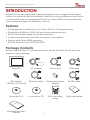
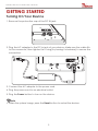
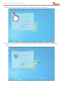
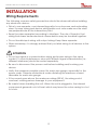
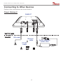
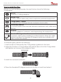
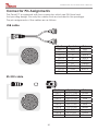
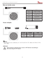
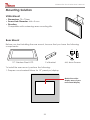
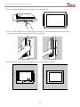
Full IP65 Stainless Flat Touch Series Class I Division II User Manual Version 1.0 Stainless Flat Touch Series User’s Manual FCC Statement This device complies with part 15 FCC rules. Operation is subject to the following two conditions: • This device may not cause harmful interference. • This device must accept any interference received including interference that may cause undesired operation. This equipment has been tested and found to comply with the limits for a class “a” digital device, pursuant to part 15 of the FCC rules. These limits are designed to provide reasonable protection against harmful interference when the equipment is operated in a commercial environment. This equipment generates, uses, and can radiate radio frequency energy and, if not installed and used in accordance with the instruction manual, may cause harmful interference to radio communications. Operation of this equipment in a residential area is likely to cause harmful interference in which case the user will be required to correct the interference at him own expense. Copyright Notice No part of this document may be reproduced, copied, translated, or transmitted in any form or by any means, electronic or mechanical, for any purpose, without the prior written permission of the original manufacturer. Trademark Acknowledgement Brand and product names are trademarks or registered trademarks of their respective owners. Disclaimer We reserves the right to make changes, without notice, to any product, including circuits and/or software described or contained in this manual in order to improve design and/or performance. We assume no responsibility or liability for the use of the described product(s), conveys no license or title under any patent, copyright, or masks work rights to these products, and makes no representations or warranties that these products are free from patent, copyright, or mask work right infringement, unless otherwise specified. Applications that are described in this manual are for illustration purposes only. We make no representation or warranty that such application will be suitable for the specified use without further testing or modification. 2 Stainless Flat Touch Series User’s Manual Warranty Our warranty that each of its products will be free from material and workmanship defects for a period of one year from the invoice date. If the customer discovers a defect, we will, at its option, repair or replace the defective product at no charge to the customer, provided it is returned during the warranty period of one year, with transportation charges prepaid. The returned product must be properly packaged in it’s original packaging to obtain warranty service. If the serial number and the product shipping data differ by over 30 days, the in-warranty service will be made according to the shipping date. In the serial numbers the third and fourth two digits give the year of manufacture, and the fifth digit means the month (e. g., with A for October, B for November and C for December). For example, the serial number 1W08Axxxxxxxx means October of year 2008. Customer Service We provide service guide for any problem as follow steps: First, visit the website of our distributor to find the update information about the product. Second, contact with your distributor, sales representative, or our customer service center for technical support if you need additional assistance. You may have the following information ready before you call: • Product serial number • Peripheral attachments • Software (OS, version, application software, etc.) • Description of complete problem • The exact wording of any error messages In addition, free technical support is available from our engineers every business day. We are always ready to give advice on application requirements or specific information on the installation and operation of any of our products. Please do not hesitate to call or e-mail us. 3 Stainless Flat Touch Series User’s Manual Safety Information WARNING! Caution! Always completely disconnect the power cord from your chassis whenever you work with the hardware. Do not make connections while the power is on. Sensitive electronic components can be damaged by sudden power surges. Only experienced electronics personnel should open the PC chassis. Always ground yourself to remove any static charge before touching the CPU card. Modern electronic devices are very sensitive to static electric charges. As a safety precaution, use a grounding wrist strap at all times. Place all electronic components in a static-dissipative surface or static-shielded bag when they are not in the chassis. Safety Precautions • Please read these safety instructions carefully. • Please keep this user’s manual for later reference. • Please disconnect this equipment from any AC outlet before cleaning. Do not use liquid or spray detergents for cleaning. Use a damp cloth. • Do not touch the LCD panel surface with sharp or hard objects. • For pluggable equipment, the power outlet must be installed near the equipment and must be easily accessible. • Keep this equipment away from humidity. • Place this equipment on a reliable surface during installation. Dropping it or letting it fall could cause damage. • The openings on the enclosure are for air convection. Protect the equipment from overheating. DO NOT COVER THE OPENINGS. • Make sure the voltage of the power source is correct before connecting the equipment to the power outlet. • Position the power cord so that people cannot step on it. Do not place anything over the power cord. • All cautions and warnings on the equipment should be noted. • If the equipment is not used for a long time, disconnect it from the power source to avoid damage by transient over-voltage. • Never pour any liquid into an opening. This could cause fire or electrical shock. • Never open the equipment. For safety reasons, only qualified service personnel should open the equipment. 4 Stainless Flat Touch Series User’s Manual • If any of the following situations arises, get the equipment checked by service personnel: The power cord or plug is damaged. Liquid has penetrated into the equipment. The equipment has been exposed to moisture. The equipment does not work well, or you cannot get it to work according to the user’s manual. The equipment has been dropped and damaged. The equipment has obvious signs of breakage. • Do not leave this equipment in an uncontrolled environment where the storage temperature is below -20°C (-4°F) or above 40°C (104°F). It may damage the equipment. • Caution – Use recommended mounting apparatus to avoid risk of injury. • WARNING – Only use the connection cords which comes along with the product, when in doubt, please contact the manufacturer. • Provision shall be made to provide transient protection device to be set at a level not exceeding 140% of the rated voltage at the power supply terminals of the apparatus. • WARNING – Explosion Hazard – Do not disconnect equipment unless power has been switched off or the area is known to be non-hazardous. • WARNING – Explosion Hazard – Substitution of components may impair suitability for Class I, Division 2. • WARNING – The equipment should be adequately protected from direct light when installed indoor or outdoor. 5 Stainless Flat Touch Series User’s Manual CONTENTS INTRODUCTION..........................................................................7 Features................................................................................................... 7 Package Contents................................................................................. 7 Product Overview.................................................................................. 8 GETTING STARTED......................................................................9 Turning On Your Device......................................................................... 9 Adjusting the LCD Display Brightness................................................. 10 Calibrating Touch Screen................................................................... 11 Turning Off Your Device....................................................................... 14 INSTALLATION..........................................................................15 Wiring Requirements............................................................................ 15 Connecting the Interface................................................................... 16 Connecting to Other Devices............................................................ 17 Connector Pin Assignments................................................................ 20 Mounting Solution................................................................................ 22 SPECIFICATIONS......................................................................24 Hardware Specifications..................................................................... 24 APPENDIX................................................................................26 Appendix A: Cleaning the Monitor.................................................... 26 Appendix B: Statement of Regulatory Approval.............................. 27 6 Stainless Flat Touch Series User’s Manual INTRODUCTION Winmate’s true-flat screen and stainless housing provide a rugged and elegant solution for industrial harsh environment. Resistive touch providing accurate touch control for the users. Accompanying Dual Core Atom N2600 processor provides user a stable and high cost efficiency solution. Features • This Equipment is suitable for use in Class I, Division 2, Hazardous area • Designed with NEMA 4 (IP65) dust poof and water protection • Robust and fanless design for reliable operation • Fanless Cooling System and Ultra Low power consumption • Support Intel Atom N2600 processor • ELO 5W Resistive Touch (R15ID3S-65FTE) Package Contents Before using this Panel PC, please make sure that all the items listed below are present in your package: Panel PC AC adapter Power cord USB cable USB adapter (USB Type A to Type B) Ethernet cable Ethernet extension adapter RS-232 cable uide ck G Qui Touch driver CD VESA mounting screws U se rM an ua l Recovery DVD Motherboard user’s manual 7 Quick start guide Stainless Flat Touch Series User’s Manual Product Overview Front View Touch Display Side and Rear Views Reset button Power button 100 VESA mounting holes M4 100 M4 M4 VESA mounting holes RESET GND DC Input USB 2.0 port GND DC IN (12V DC in) jack COM (RS232) port Ethernet port LED Indicators RESET LED Type Power ( Storage ( ) ) Status Description On Power is on. Off Power is off. Blinking Off Storage activity (data is being read or written). System is idle. 8 Stainless Flat Touch Series User’s Manual GETTING STARTED Turning On Your Device 1. Remove the protective cap of the DC IN jack. RESET GND DC Input 2. Plug the AC adapter to the DC-in jack of your device. Make sure the cable fits to the connector, then tighten the O-ring (by turning it clockwise) to secure the connection. RESET GND DC Input 3. Connect the AC adapter to the power cord. 4. Plug the power cord to an electrical outlet. 5. Plug the Power button to turn on the device. Note • When the system hangs, press the Reset button to restart the device. 9 Stainless Flat Touch Series User’s Manual Adjusting the LCD Display Brightness 1. Tap the arrow on the system tray to display the hidden icons. 2. Double-tap the menu. icon to display the brightness 3. Drag the brightness bar to adjust the brightness level according to your preference. 10 Stainless Flat Touch Series User’s Manual Calibrating Touch Screen When turning on the Panel PC for the first time, it is highly recommended to calibrate the touch screen to ensure touch accuracy. Five-wire resistive touchscreens The five-wire resistive touchscreens use a glass panel with a uniform resistive coating. A thick polyester coversheet is tightly suspended over the top of the glass, separated by small, transparent insulating dots. The coversheet has a hard, durable coating on the outer side and a conductive coating on the inner side. A B A C B D C D E F E F When the screen is touched, the conductive coating makes electrical contact with the coating on the glass. The voltages produced are the analog representation of the position touched. The controller digitizes these voltages and transmits them to the computer for processing. The five-wire technology utilizes the bottom substrate for both X and Y-axis measurements. The flexible coversheet acts only as a voltage-measuring probe. This means the touchscreen will continue working properly even with non-uniformity in the cover sheet’s conductive coating. The result is an accurate, durable and reliable touchscreen that offers drift free operation. The touchscreens are sealed against contamination and moisture. The coversheet is sealed to the glass substrate with an industrial grade caulk. This prevents wicking of fluid between the coversheet and glass. Also, the touchscreens are not air vented, thereby preventing fluid ingress through an air vent. Brief Specifications Subject Details Input Method Finger, gloved hand, or stylus activation Positional Accuracy Standard deviation error is less than 0.080 (2 mm) Resolution Touch point density is based on controller resolution of 4096 x 4096 Touch Activation Force Typically less than 4 ounces (113 grams) Light Transmission HL products: 80% +/–5% at 550 nm wavelength Enhanced products: 60% +/–5% at 550 nm wavelength Update touch-screen driver or new information. Go to www.elotouch.com. 11 Stainless Flat Touch Series User’s Manual Elo Touch Correction Winmate ELO Touch driver software provides a consistent software interface among all ELO touch screens and controllers. Go to http://www.elotouch.com/Support/dnld.asp for a complete list of available supports. After the driver installation is complete, do the following to perform touch screen calibration. 1. Tap the arrow on the system tray to display the hidden icons. 2. Double-tap the icon to display the Elo Touchscreen menu. 3. Double-tap the icon to proceed to next step. 12 Stainless Flat Touch Series User’s Manual 3. Follow the on-screen instructions to calibrate the touch screen. 4. Tap the utility. icon if the cursor follows your finger to finish and exit the calibration 13 Stainless Flat Touch Series User’s Manual Turning Off Your Device To shut down your device, do the following: Tap Start ( ) > Shut down. Wait for your Panel PC to completely turn off before disconnecting the power cord (if necessary). 14 Stainless Flat Touch Series User’s Manual INSTALLATION Wiring Requirements The following common safety precautions should be observed before installing any electronic device: • Strive to use separate, non-intersecting paths to route power and networking wires. If power wiring and device wiring paths must cross make sure the wires are perpendicular at the intersection point. • Keep the wires separated according to interface. The rule of thumb is that wiring that shares similar electrical characteristics may be bundled together. • Do not bundle input wiring with output wiring. Keep them separate. • When necessary, it is strongly advised that you label wiring to all devices in the system. ATTENTION • Do not run signal or communication wiring and power wiring in the same conduit. To avoid interference, wires with different signal characteristics (i.e., different interfaces) should be routed separately. • Be sure to disconnect the power cord before installing and/or wiring your device. • Verify the maximum possible current for each wire gauge, especially for the power cords. Observe all electrical codes dictating the maximum current allowable for each wire gauge. • If the current goes above the maximum ratings (80 W), the wiring could overheat, causing serious damage to your equipment. • Be careful when handling the unit. When the unit is plugged in, the internal components generate a lot of heat which may leave the outer casing too hot to touch. 15 Stainless Flat Touch Series User’s Manual Connecting the Interface This Panel PC comes with various interfaces located on the bottom panel. All of these connectors have been shipped with protective caps and tethers. If you wish to detach the tethers, the screws securing them to the bottom panel will need to be removed. To ensure the waterproof function can work properly, make sure that the protective caps and the tethers have been securely fastened whenever the connectors are not used. RESET GND DC Input IMPORTANT Please note that when reinstalling the protective cap, it must be fully tightened to ensure the unit is properly sealed to meet the IP65 enclosure rating. 16 Stainless Flat Touch Series User’s Manual Connecting to Other Devices Perform the connections as shown below. Class I, Division 2 PANEL PC RESET GND DC Input HAZARDOUS AREA SAFE AREA USB cable Ethernet cable RS-232 cable 17 Power adapter & power cord Stainless Flat Touch Series User’s Manual ATEX HAZARDOUS AREA SAFE AREA Ethernet cable SAFETY EARTH GROUND STUD ON BACK PANEL Connect to SUITABLE EARTH GROUND Power adapter & power cord RS-232 cable USB cable 18 Stainless Flat Touch Series User’s Manual How to install the Pipe Before you start installing the pipe, be sure that you have the following components: Slip Nut To secure “L” fitting adaptors. Stopper Plugs To close unused cable entry holes in explosion protected equipment. O-Ring Rubber / Gasket To maintain the IP Rating between equipment and cable. Conversion reducers To convert thread forms and size between equipment and cable entry devices. Locknuts To secure adaptors / reducers, and stopper plugs into equipment. Threaded 90-degree bends To protect cables when installed in confined spaces where the cable may be bending. This threaded 90-degree bends are available with male connection threads. To install the pipe, perform the following: 1. Insert the slip nut followed by the O-ring rubber/ gasket into the tube. 2. Adjust the location of O-ring rubber and pull the slip nut into the O-ring rubber and tighten up to ensure the waterproof seal. Pull it upwards 3. Install the conversion reducers. 4. Place the threaded 90-degree bends into the slip nut and then fasten it. 19 Stainless Flat Touch Series User’s Manual Connector Pin Assignments This Panel PC is equipped with four connectors which are IP65 level and fool-proofing design. Use only the cables that are included in the package. The pin assignments of the cables are as follows: USB cable 2 1 10 9 5 6 3 Pin No. CN1-1 CN1-2 CN1-3 CN1-4 CN1-5 CN1-6 CN1-7 CN1-8 CN1-9 8 4 7 Symbols Color VCC RED VCC RED DWHITE DWHITE D+ GREEN D+ GREEN GND BLACK GND BLACK Braid RS-232 cable 3 2 4 10 1 11 5 12 9 8 Pin No. CN2-1 CN2-2 CN2-3 CN2-4 CN2-5 CN2-6 CN2-7 CN2-8 CN2-9 7 6 20 Symbols DCD-CON2 DSR-CON2 RXD-CON2 RTS-CON2 TXD-CON2 CTS-CON2 DTR-CON2 RI-CON2 GND-CON2 Color Green Brown Red Orange Blue White Purple Yellow Black Stainless Flat Touch Series User’s Manual Ethernet (LAN) cable 3 2 4 10 1 11 5 12 9 8 Pin No. CN2-1 CN2-2 CN2-3 CN2-4 CN2-5 CN2-6 CN2-7 CN2-8 7 6 Color White/Orange Orange White/Green Blue White/Blue Green White/Brown Brown Power adapter 3 1 2 Pin No. CN2-1 CN2-2 CN2-3 Symbols VCC GND GND Color Follow Adapter Follow Adapter Follow Adapter Note • This adapter was certified by UL, CUL TUV/GS CE, FCC, BSMI, EK, DOIR+C-TICK, CCC, PSE. WARNING Ensure that the external power source is OFF before connecting or disconnecting the DC IN jack. 21 Stainless Flat Touch Series User’s Manual Mounting Solution VESA Mount • Dimensions: 75 x 75mm • Screw Hole Diameter: M4 x 5 mm • Direction: Compatible with swimming arms mounting kits. Rear Mount Before you start installing the rear mount, be sure that you have the following components: 9 4 M4 6 15” Stainless Steel LCD 2 x Bracket M4, 4mm Screws To install the rear mount, perform the following: 1. Prepare a customized fixture for 15” panel pc/display. Match the active display area of your rear mount display 22 Stainless Flat Touch Series User’s Manual 2. Screw the brackets on both sides of your device. RESET 3. Secure the display from the back side first, so the outer frame can be fully covered to ensure the safety of your display. RESET RESET 4. Make sure your screws are tight and on the right position. RESET GND DC Input 23 Stainless Flat Touch Series User’s Manual SPECIFICATIONS Hardware Specifications Item Specifications Computer CPU Intel Dual Core Atom N2600 1.6GHz processor OS Windows 7 embedded systems System Chipset Intel NM10 Bios AMI 16Mbit Flash System Memory 4GB capacity, 2GB pre-installed USB 2 x USB 2.0 Storage Storage Support Removable 32GB industrial grade SSD to store OS; support up to 256GB Display Panel Size 15-inch 1024 x 768, 600nit LED backlight LCD Contrast Ratio 700:1 Response Time 8ms View Angles • Horizontal: 160 degree (left to right) • Vertical: 140 degree (up to down) Max Colors 16.2M colors Touch ELO Flat Resistive single point touch, suitable for use outdoors around heavy equipment Ethernet Interface Hardware Interface Waterproof RJ45 connector Serial Interface Serial Standard 1x RS232/RS422/RS485 pre-selectable by jumper Connector Type Waterproof DB9 (male) Power Requirements Input Voltage Typical 12V DC (isolation 800V) 24 Stainless Flat Touch Series User’s Manual Item Specifications Physical Characteristics Housing Stainlesssteel Dimensions 396 x 310 x 49mm (W x H x D) Mounting MountingholeforVESA100x100,yokemounting Environment Limits Operating Temperature -20°C to 40°C StorageTemperature -40°C to 80°C AmbientRelativeHumidity 30 to 95% (non-condensing) StandardandCertification Hazardous Environments • UL Class 1 Division 2 • ISA12.12.01-2012 • CSAC22.2No.213-M1987 • CSA22.2No.60950-1-07 • FCC • CE 25 Stainless Flat Touch Series User’s Manual APPENDIX Appendix A: Cleaning the Monitor Before cleaning: • Make sure the device is turned off. • Disconnect the power cable from any AC outlet. When cleaning: • Never spray or pour any liquid directly on the screen or case. • Wipe the screen with a clean, soft, lint-free cloth. This removes dust and other particles. • The display area is highly prone to scratching. Do not use ketene type material (ex. Acetone), Ethyl alcohol, toluene, ethyl acid or Methyl chloride to clear the panel. It may permanently damage the panel and void the warranty. • If it is still not clean enough, apply a small amount of non-ammonia, non-alcohol based glass cleaner onto a clean, soft, lint-free cloth, and wipe the screen. • Don not use water or oil directly on the display screen. If droplets are allowed to drop on the screen, permanent staining or discoloration may occur. 26 Stainless Flat Touch Series User’s Manual Appendix B: Statement of Regulatory Approval Referthefollowingdescriptionsforvariousapprovalsandcertifications. N. A. Safety for Information Technology Equipment CertificationbyUnderwriter’sLaboratoriestoUL60950-1,2ndEdition standardandequivalentCSAC22.2No60950-1-07,2ndEdition Standard N. A. Safety for Hazardous Locations Class I, Div. 2, Groups A, B, C, D CertificationbyUnderwriter’sLaboratoriestoANSI/ISA12.12.01-2012standardandequivalentCAN/CSAC22.2No 213-M1987Standard Low Voltage Directive European Safety for Industrial Control Equipment Self-DeclarationinaccordancewithEuropeanLVDDirective 2006/95/EC;Independent3rdpartyassessment(AccreditedbyIEC 17025) Electromagnetic Compatibility Directive European EMC for Industrial Control Equipment Self-DeclarationinaccordancewithEMCDirective2004/108/EC; Independent3rdpartyassessment(AccreditedbyIEC17025) 27


![User Manual [ ] - American Industrial Systems, Inc.](http://vs1.manualzilla.com/store/data/005674734_2-58a82461c9fcf90cc8d42d376dad67a0-150x150.png)