1
Operating instructions, part 1
RDT 100 F001 / F002
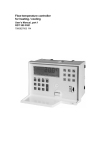
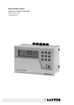
Controller for ventilation and
air-conditioning
7 000 835 003 M7
About these operating instructions
With the RDT 100 controller for ventilation and air-conditioning, you are in receipt of two
documents as follows:Part 1 (7 000 835) of these operating instructions contains all necessary information on
manual and automatic modes. It is intended primarily for the user.
Part 2 (7 000 836) of the operating instructions describes how to put the controller into
operation and is intended for the specialist. It also contains detailed information for project
engineers and interested users.
The operating procedures have been described in this manual with the aid of illustrations.
When entering numerical values, all positions must be filled, including preceding noughts.
Example: 20.5 °C
Enter: 0205
In manual and automatic modes, incomplete entries are aborted automatically after two
minutes. The value already entered remains unchanged. Entries are accepted only if in
the permissible range, or are restricted thereto.
The position requiring an input flashes in the display (user prompting) and is marked in
this manual by an arrow.
Follow the various input stations, press the corresponding keys and observe the result in
the display.
To make it easier to find a function group in any of the sections, some pages are marked
with the letters 'B', 'P' or 'E' and the appropriate page number.
B = Operation
P = Parameters
E = Setting
For details on parameters: see part - -, page
Settings: see part - -, page
Explanations on the parameters can be found in part 2, page 12.
Changes to the default values can be entered in part 2, page 62.
P 2-12
E 2-62
1-1
List of contents
General information .......................................................................................................... 3
Putting into operation .......................................................................................................... 3
Recommended procedure................................................................................................... 3
Reaction in the event of a power failure .............................................................................. 3
Front view of controller .................................................................................................... 4
The information centre ..................................................................................................... 5
Control deviation Xw ........................................................................................................... 6
Examples ............................................................................................................................ 7
Input method ..................................................................................................................... 8
Automatic mode
......................................................................................................... 9
View actual values ............................................................................................................ 10
View control deviation ....................................................................................................... 10
View and alter setpoints .................................................................................................... 11
View positioning signals and output variables ................................................................... 12
Models 0...14 ............................................................................................................................ 12
Models 15...18 .......................................................................................................................... 12
Models 20...29 .......................................................................................................................... 13
Models 30...35 .......................................................................................................................... 13
Manual mode
........................................................................................................ 15
View actual values ............................................................................................................ 16
View control deviation ....................................................................................................... 16
View and alter setpoints .................................................................................................... 16
View and alter positioning signals; view output variables .................................................. 17
Models 0...14 ............................................................................................................................ 17
Models 15...18 .......................................................................................................................... 18
Models 20...29 .......................................................................................................................... 19
Models 30...35 .......................................................................................................................... 20
View and alter control parameters..................................................................................... 21
Models 0...14 ............................................................................................................................ 21
Models 15...18 .......................................................................................................................... 22
Models 20...29 .......................................................................................................................... 23
Models 30...35 .......................................................................................................................... 24
1-2
1-3
General information
Putting into operation
As soon as it has been switched on, the RDT 100 controller for ventilation and airconditioning is ready for operation if a control model has been chosen and the power supply is connected.
Please observe the correct power supply for each model type as follows:F001 requires 230 V~
F002 requires 24 V~
The stored factory settings (default settings) for the parameters for each control model
permit immediate control operations. These default settings are highlighted (shaded grey)
in this manual, and are designed for normal temperature control loops. Some of the default settings of some control models differ from the highlighted values.
Recommended procedure
− Familiarise yourself with the controller's operating methods. Refer to the description of
the front and the ‘information centre’.
− Choose the appropriate control model in accordance with the technical remit, e.g. the
flow diagram. The configuration values need to be entered (once only) in the service
level.
− Enter the control model's number. This stipulates the function in accordance with the
block diagram on the wiring diagram. The data inputs must also be encoded by means
of the jumper. All other inputs are done via the keypad. In the service level, it is advisable to make the entries in the right order.
− Set the mode switch to ‘Automatic’. The controller starts with the default values for the
setpoints, P-band etc.
− Watch the plant; if necessary, match the parameters to the specific needs of the plant.
Reaction in the event of a power failure
All data and parameters are captive. In the event of a power failure, the continuous outputs drop to 0 Volt, the relay outputs cut out and the display goes blank. When power has
been restored, the controller re-starts with the stored parameters. This also applies for
long power failures.
1-4
Front view of controller
Mode switch
Flap holds instructions Memory (option)
Manual mode
Automatic
Service level
Service and adjustment keys
0 ... 9
Numerical keys
PAR
Control parameters
User keys with
function keys
Xs Setpoint
Xi Actual value
XW Control deviation
SERV
Service
Cl Clear
Information centre
Y Positioning signal
I
Input
Forwards
Backwards and
minus sign
B06968
1-5
The information centre
Value with preceding mathematical sign and unit
Parameters
Xw (see also next page)
Control action, min. or max. limitation,
open/close/on command
for switching outputs
Operating modes:- Control (Automatic)
- Manual
External setpoint
active
Service level
Enter control parameters
B06969a
1-6
Control deviation Xw
Definition:Control deviation = actual value – setpoint
Xw = Xi – Xs
For differential controllers:Control deviation = calculated action value – setpoint
Xw = cXi – Xs
B06970
Positive control deviation
Control deviation Xw
<
>
1,5
1,0
0,2
50
1,5
1,0
0,2
50
3,0
2,0
0,4
100
7,5 15,0
5,0 10,0
1,0 2,0
250 500
Negative control deviation
Unit of meas.
°C
%, % r.H., kJ/kg
g/kg
- 1)
Control deviation Xw
<
<
-1,5
-1,0
-0,2
-50
-1,5
-1,0
-0,2
-50
-3,0
-2,0
-0,4
-100
-7,5 -15,0
-5,0 -10,0
-1,0 -2,0
-250 -500
B06971a
1)
Free unit of measurement: with respect to displayed range 0...4999
1-7
Examples
−
−
−
−
Automatic mode
Actual value Xi3 with unit °C
Xw in display
External setpoint active
B06975
− Manual mode
− Input for control parameters
− Integral action time for
controller 1
B06976
− Service level
− Upper setpoint limit 50.0 °C
B06977
− Service level
− Minimum limitation Y2
ready for the input of the first
position
B06978
1-8
For details on parameters: see part - -, page
Input method
P ????
E ????
Settings: see part - -, page
Function key for positioning signals
Y
It is possible to choose
the function in this mode
On changing from
Auto
Manual,
the prevailing
positioning signal
is accepted.
4. When complete, the input is accepted
Input
Cl
Y_
3. Valid range
0 . . . 100 %
1. Delete display; the position
requiring an input flashes
2. Enter the value
List of possible
parameters
Positioning signal Y1
Y1
Positioning signal Y2
Y2
I
3. Press the 'I' key to have the entry accepted!
Input
Y. + 2%
I
Output variable Y3
Yc1
- Controller 2 (Pl 2)
Yc2
Input
Y. - 2%
Y3
Calculated pos. signals:- Controller 1 (Pl 1)
Y_
1. Delete display; the position
requiring an input flashed
2. Correction in steps
Certain values, e.g. actual values and calculated positioning signals,
can be viewed but not altered.
20,0°C
Factory settings (default values), where applicable, are shaded grey.
- This key is used to enter a negative sign.
Y1 - Y2 - Y3 - Yc1 - Yc2
Use the 'forwards' or 'backwards' keys to choose the desired parameter.
There are two input methods:- Begin with
Cl
- Begin with
I
to enter the value; it is accepted when complete.
for toggle entries; input is accepted after you have again pressed the
I
key.
B06979
Auto
Automatic mode
Control in accordance with the setpoint
1-9
1 - 10
Auto
View actual values
P
E
2-16
–
P
E
2-17
–
Xi
Actual values
Xi1
Xi2
Xi3
Xi4
B06980
View control deviation
Xw
Control deviation
- Controller 1 (PI 1)
Xw1
- Controller 2 (PI 2)
Xw2
Xw = Xi - Xs
For differential
controllers:
Xw = cXi - Xs
B06981
1 - 11
Auto
P
E
View and alter setpoints
Xs
I
2-11/17
2-63
Press button to change setpoint
Input
Setpoint for:
- Controller 1 (Pl 1)
Xs1
20,0°C
- Controller 2 (Pl 2)
Xs2
20,0°C
Xs. + . . .
I
_Xs_
Input
Xs. - . . .
Setpoint Xs external
(affects controller 1)
+/- 0,5 °C
+/- 1 %, % r.H.
+/- 0,2 g/kg
+/- 0,2 kJ/kg
XsE
Free unit restricted
to range
Calculated setpoint,
only on the modes
with command modul
- Controller 1 (Pl 1)
cXs1
- Controller 2 (Pl 2)
or aux. controller
of cascade
cXs2
B06982
1 - 12
Auto
View positioning signals and output variables
Models 0...14
P
E
2-18
–
P
E
2-18
–
Y
Positioning signal Y1
Y1
Positioning signal Y2
Y2
Output variable Y3
Y3
Calculated pos. signals:- Controller 1 (Pl 1)
Yc1
- Controller 2 (Pl 2)
Yc2
B06983
View positioning signals and output variables
Models 15...18
Y
Displayed:
2-point output
- On
- Off
Pos. signal Y1 (continuous)
Y1
Pos. signal Y2, Relay 2
(switching)
Y2
Output variable Y3
Y3
Calculated pos. signals:- Controller 1 (Pl 1)
Yc1
- Controller 2 (Pl 2)
Yc2
B06984
1 - 13
Auto
View positioning signals and output variables
Models 20...29
Y
P
E
2-18
–
P
E
2-18
–
Displayed:
2-point output
- On
- Off
Pos. signal Y1, Relay 1
Y1
Pos. signal Y2, Relay 2
Y2
Output variable Y3
Y3
Calculated pos. signals:- Controller 1 (Pt 1)
Yc1
- Controller 2 (Pt 2)
Yc2
B06985
View positioning signals and output variables
Models 30...35
Y
Displayed:
3-point output
- Open
- Stop
- Closed
Pos. signal Y1, Relays 1 + 2
Y1
Output variable Y3
Y3
Calculated pos. signals:- Controller 1 (Pl 1)
Yc1
- Controller 2 (Pl 2)
Yc2
B06986
1 - 14
Auto
Manual
Manual mode
In this mode, you can:– set the positioning signals between 0...100%
– alter the setpoints
– set the control parameters.
1 - 15
1 - 16
Manual
P
E
View actual values
2-11/17
–
Xi
Actual values
Xi1
Xi2
Xi3
Xi4
B06987
View control deviation
P
E
2-17
–
P
E
2-11
2-63
Xw
Control deviation
- Controller 1 (PI 1)
Xw1
- Controller 2 (PI 2)
Xw2
Xw = Xi - Xs
For differential
controllers:
Xw = cXi - Xs
B06988
View and alter setpoints
Xs
Setpoint for:
Input
- Controller 1 (Pl 1)
Xs1
20,0°C
- Controlelr 2 (Pl 2)
Xs2
20,0°C
Setpoint Xs external
(affects controller 1)
XsE
Calculated setpoint
- Controller 1 (Pl 1)
- Controller 2 (Pl 2),
or aux. controller
of cascade
cXs1
Cl
_Xs_
-30,0...150,0 °C
0,0...100,0 %, % r.H.
0,0...20,0 g/kg
0,0...100,0 kJ/kg
-4999...+4999
For diff. controller:
0,0...150,0 °C
cXs2
B06989
1 - 17
Manual
View and alter positioning signals; view output variables
P
E
Models 0...14
Y
On changing from
Auto
Manual,
the prevailing
positioning signal
is accepted
2-18
–
Input
Cl
Y_
0 . . . 100 %
Positioning signal Y1
Y1
Positioning signal Y2
Y2
I
Press button to change positioning signal
Input
Y. + 2%
I
Output variable Y3
Y3
Y_
Input
Y. - 2%
Calculated pos. signals:- Controller 1 (Pl 1)
Yc1
- Controller 2 (Pl 2)
Yc2
B06990
1 - 18
Manual
View and alter positioning signals; view output variables
P
E
Models 15...18
Y
2-18
–
On changing from
Auto
Manual,
the prevailing
positioning signal
is accepted
Displayed:
2-point output
- On
- Off
Cl
Pos. signal Y1 (continuous)
Input
Y_
Y1
0 . . . 100 %
I
Press button to change positioning signal
Input
Y. + 2%
I
Y_
Input
Y. - 2%
Pos. signal Y2, Relay 2
Y2
Input
Continuously on
I
Y_
Input
Continuously off
Output variable
Y3
Calculated pos. signals:- Controller 1 (Pl 1)
Yc1
- Controller 2 (Pl 2)
Yc2
B06991
1 - 19
Manual
View and alter positioning signals; view output variables
P
E
Models 20...29
Y
2-18
–
On changing from
Auto
Manual,
the prevailing
relay position is
accepted
Displayed:
2-point output
- On
- Off
I
Input
Pos. signal Y1, Relay 1
Continuously on
Y1
I
Pos. signal Y2, Relay 2
Y2
Y_
Input
Continuously off
Output variable Y3
Y3
Calculated pos. signals:- Controller 1 (Pt 1)
Yc1
- Controller 2 (Pt 2)
Yc2
B06992
1 - 20
Manual
View and alter positioning signals; view output variables
P
E
Models 30...35
Y
2-18
–
Displayed:
3-point output
- Open
- Stop
- Closed
I
Input
Pos. signal Y1, Relay 1 + 2
'Open' pulse 1)
Y1
I
Y_
Input
'Close' pulse 1)
Output variable Y3
Y3
Calculated pos. signals:- Controller 1 (PI 1)
Yc1
- Controller 2 (PI 2)
Yc2
1) Pulse duration is 2% of motor's running time Tm.
B06993
1 - 21
Manual
View and alter control parameters
P
E
Models 0...14
2-12/13/15/21
2-62/63
PAR
6
Input
Cl
Controller 1 (Pl 1)
- Proportional band
Xp1
- Integral action time
Tn1
10,0°C
Xp.:
0,1...250,0 °C
0,1...200,0 %
0,1...100,0 % r.H.
0,1...20,0 g/kg
0,1...100 kJ/kg
1...4999
0
Tn:
0...9990 s
Command module:
- Start of shift
FP
-30,0°C
- End of shift
F1
150,0°C
- Amount of shift
Ws
0,0°C
Cascade, aux. control. (Pl 2)
- Upper setpoint limit
rXSc
28,0°C
- Lower setpoint limit
rXSc
18,0°C
Input
Cl
FP, F1, rXSc:
-30,0...150,0 °C
0,0...200,0 %
0,0...100,0 % r.H.
0,0...20,0 g/kg
0,0...100,0 kJ/kg
-4999...+4999
Ws:
0,0...150,0 °C
0,0...200,0 °C
0,0...100,0 % r.H.
0,0...20,0 g/kg
0,0...100,0 kJ/kg
Controller 2 (Pl 2)
- Proportional band
Xp2
- Integral action time
Tn2
10,0°C
0
Software version
VER
_._
Type of device
R-
---
Input
Cl
Xp.:
0,1...250,0 °C
0,1...200,0 %
0,1...100,0 % r.H.
0,1...20,0 g/kg
0,0...100,0 kJ/kg
1...4999
Tn:
0...9990 s
B06994
1 - 22
Manual
View and alter control parameters
P
E
Models 15...18
2-12/13/15/21/22
2-62/63
PAR
6
Input
Cl
Switching difference of
Relay output 2
XSd
20%
XSd
0,0 . . . 100,0 %
Controller 1 (Pl 1)
- Proportional band
Xp1
- Integral action time
Tn1
1)
10,0°C
0
Input
Cl
Xp.:
0,1...250,0 °C
0,1...200,0 %
0,1...100,0 % r.H.
0,1...20,0 g/kg
0,1...100 kJ/kg
1...4999
Tn:
0...9990 s
Command module:
- Start of shift
FP
-30,0°C
- End of shift
F1
150,0°C
Input
- Amount of shift
Ws
0,0°C
Cascade, aux. control. (Pl 2)
- Upper setpoint limit
rXSc
28,0°C
- Lower setpoint limit
rXSc
18,0°C
Cl
FP, F1, rXSc:
-30,0...150,0 °C
0,0...200,0 %
0,0...100,0 % r.H.
0,0...20,0 g/kg
0,0...100,0 kJ/kg
-4999...+4999
Ws:
0,0...150,0 °C
0,0...200,0 °C
0,0...100,0 % r.H.
0,0...20,0 g/kg
0,0...100,0 kJ/kg
Controller 2 (Pl 2)
- Proportional band
Xp2
- Integral action time
Tn2
10,0°C
0
Software version
VER
_._
Type of device
R-
---
Input
Cl
Xp.:
0,1...250,0 °C
0,1...200,0 %
0,1...100,0 % r.H.
0,1...20,0 g/kg
0,1...100 kJ/kg
1...4999
Tn:
0...9990 s
1) The input range is restricted by the value bY2.
B06995
1 - 23
Manual
View and alter control parameters
P
E
Models 20...29
2-12/12/15/17/21/22
2-62/63
PAR
6
Input
Cl
Controller 1 (2Pt), Relay 1
- Switching difference
XSd1
1
XSd
2,0°C
XSd1:
0,1...250,0 °C
0,1...200,0 %
0,1...100,0 % r.H.
0,1...20,0 g/kg
0,1...100 kJ/kg
1...4999
Command module:
- Start of shift
FP
-30,0°C
- End of shift
F1
150,0°C
- Amount of shift
Ws
0,0°C
Input
Cl
FP, F1:
-30,0...150,0 °C
0,0...200,0 %
0,0...100,0 % r.H.
0,0...20,0 g/kg
0,0...100,0 kJ/kg
-4999...+4999
Ws:
0,0...150,0 °C
0,0...200,0 °C
0,0...100,0 % r.H.
0,0...20,0 g/kg
0,0...100,0 kJ/kg
Controller 2 (2Pt), Relay 2
- Switching difference
XSd2
2,0°C
Input
Cl
Software version
VER
_._
Type of device
R-
---
2
XSd
XSd2:
0,1...250,0 °C
0,1...200,0 %
0,1...100,0 % r.H.
0,1...20,0 g/kg
0,1...100 kJ/kg
1...4999
B06996
1 - 24
Manual
View and alter control parameters
P
E
Models 30...35
2-12/13/15/17/21/22
2-62/63
PAR
6
Input
Cl
Controller 1 (Pl 1)
- Proportional band
Xp1
- Integral action time
Tn1
- Switching range
Xsh
10,0°C
Xp., Xsh:
0,1...250,0 °C
0,1...200,0 %
0,1...100,0 % r.H.
0,1...20,0 g/kg
0,1...100,0 kJ/kg
1...4999
0
2,5°C
Tn:
0...9990 s
Command module:
- Start of shift
FP
-30,0°C
- End of shift
F1
150,0°C
- Amount of shift
Ws
0,0°C
Cascade, aux. control. (Pl 2)
- Upper setpoint limit
rXSc
28,0°C
- Lower setpoint limit
rXSc
18,0°C
Input
Cl
FP, F1, rXSc:
-30,0...150,0 °C
0,0...200,0 %
0,0...100,0 % r.H.
0,0...20,0 g/kg
0,0...100,0 kJ/kg
-4999...+4999
Ws:
0,0...150,0 °C
0,0...200,0 °C
0,0...100,0 % r.H.
0,0...20,0 g/kg
0,0...100,0 kJ/kg
Controller 2 (PI2)
- Proportional band
Xp2
10,0°C
- Integral action time
Tn2
0
Software version
VER
_._
Type of device
R-
---
Input
Cl
Xp.:
0,1...250,0 °C
0,1...200,0 %
0,1...100,0 % r.H.
0,1...20,0 g/kg
0,1...100,0 kJ/kg
1...4999
Tn:
0...9990 s
B06997
1 - 25
1 - 26
Printed in Switzerland
Right of amendment reserved
N.B.: A comma between cardinal
numbers denotes a decimal point
Fr. Sauter AG, CH-4016 Basle
7 000 835 003 M7