1
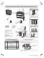
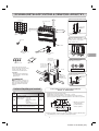
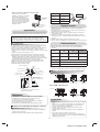
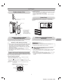
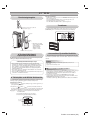
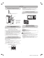
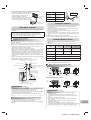
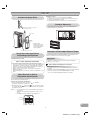
2. Put water in the drain pan and make sure that the water is drained out of
doors.
3. When connecting extension drain hose, insulate the connecting part of
extension drain hose with shield pipe.
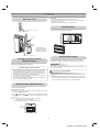
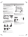
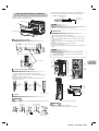
How to Install Indoor Unit
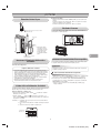
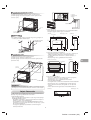
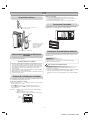
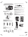
1. Remove the air inlet grille. Open the air inlet grille and remove the strap.
2. Remove the front panel (Remove the 4 screws).
Shield pipe
Extension drain hose
Front panel
Drain hose
Hook
Inside the room
CAUTION
Arrange the drain pipe for proper drainage from the unit.
Improper drainage can result in dew-dropping.
Air inlet grille
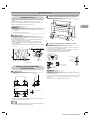
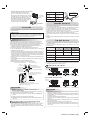
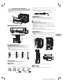
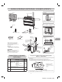
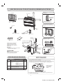
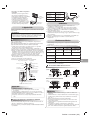
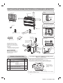
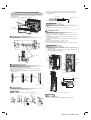
Wiring connection
Wiring of the connection cable is necessary to remove the front panel.
1. Remove the terminal cover and cord clamp.
2. Insert the connecting cable (according to the local rule) into the pipe hole
on the wall.
3. Take out the connecting cable through the cable slot on the rear panel so
that it protrudes about 50 cm from the front.
4. Insert the connecting cable fully into the terminal block and secure it
tightly with screws.
5. Tightening torque : 1.2 N·m (0.12 kgf·m)
6. Secure the connecting cable with the cord clamp.
7. Fix the terminal cover, install the front panel and grille inlet.
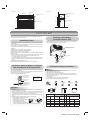
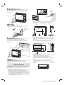
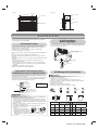
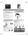
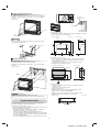
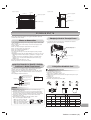
Layout of connection piping
100
542
58
85
6
112
148
64
40
85
49
40
R45
29
6
108
12
CAUTION
0
• Be sure to refer to the wiring system diagram labeled inside the front
panel.
• Check local electrical cords and also any specific wiring instructions or
limitations.
Hook
47
Terminal cover
210
163
Connection piping
49
Terminal
block
Screw
Earth line
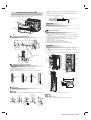
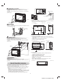
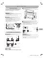
Treatment of piping connection
1) Check the flare nut connections for the gas leak with a gas leak detector
or soap water.
2) To prevent gap in slit, fasten top and bottom with tape.
3) Slit is covered with tape.
4) Fasten with supplied Insulate sheet to prevent gap on the top of slit.
Screw
Cord clamp
Earth screw
Gas leak check
Tape
Tape
110 mm
Earth line
20 mm
Slit
430 mm
9 Insulation sheet
10 mm
50 mm
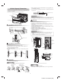
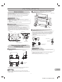
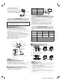
Drainage
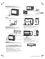
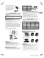
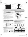
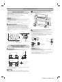
1. Run the drain hose sloped downwards.
NOTE
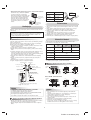
Stripping length of the connecting cable
• The hole should be made at a slight downward slant on the outdoor side.
Do not form the
drain hose into
a wavy shape.
Do not rise the
drain hose.
Do not put the
drain hose end
into water.
NOTE
• Use stranded wire only.
• Wire type : H07RN-F or 60245 IEC66 (1.0 mm2 or more)
Do not put the
drain hose end in
the drainage ditch.
5
Toshiba 1112150201 (EN)