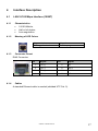
1
ONE200
Installation Manual
Version A
April 2005
http://www.oneaccess-net.com
ONE200 - Installation Manual
1
1
OneAccess
28 rue de la Redoute
92260 Fontenay aux Roses
France
The law of 11 March 1957, paragraphs 2 and 3 of article 41, only authorizes, firstly,
’copies and reproductions strictly reserved for use by copyists and not for general
use and, secondly, analyses and short quotations for the purpose of example and
illustration. Therefore, ’any representation or reproduction, entire or partial, made
without the consent of the author or his representatives is illegal’ (paragraph 1 of
article 40).
Any such representation or reproduction, made in any manner whatsoever, would
therefore constitute an infringement of the law as sanctioned by articles 425 and in
accordance with the penal code.
Information contained in this document is subject to change without prior notice and
does not constitute any form of obligation on the part of OneAccess.
OneAccess and the distributors can in no case be held responsible for direct or
indirect damage of any kind incurred as a result of any error in the software or
guide.
Every care has been taken to ensure the exactitude of information in this manual. If
however you discover an error, please contact OneAccess After Sales Service
division.
April 2005 Issue
1000 00 N 4022 844 C 00 ind. B
2
ONE200 - Installation Manual
How to Read this Manual
The present document is broken down into 7 chapters.
Chapter 1 – Safety Instructions
This chapter provides the safety instructions for use and installation of the router.
Chapter 2 – Directives and Standards
This chapter details the list of standards, which the device complies with.
Chapter 3 – Device Description
This section describes the router front and rear panels and the associated technical
characteristics.
Chapter 4 – Interface Description
This section describes the router interfaces.
Chapter 5 – Technical Characteristics
This section describes technical characteristics such as operating conditions.
Chapter 6 - Installation
This chapter describes how to mount a daughter-board and gives instructions to
connect the router.
Chapter 7 – Power-up
This chapter describes the device power-up and how to monitor the self-test
progress.
Appendix – Connection description
These chapters provide the pin-out of cables that are compatible with the router.
ONE200 - Installation Manual
3
Table of Contents
1
1.1
1.3
SAFETY INSTRUCTION ..............................................................................................................5
Connection to Power Supply ...................................................................................................5
Safety Level Interface..............................................................................................................6
2.1
2.2
2.3
DIRECTIVES AND STANDARDS................................................................................................8
Declaration of Conformity........................................................................................................8
Standards ................................................................................................................................9
FCC Startement (USA)..........................................................................................................10
3.1
3.2
3.3
3.4
3.5
DEVICE DESCRIPTION .............................................................................................................11
Hardware Description............................................................................................................11
Front Panel ............................................................................................................................12
Rear Panel ............................................................................................................................14
Mother Board.........................................................................................................................15
Configuration Identification....................................................................................................16
2
3
4
INTERFACE DESCRIPTION......................................................................................................17
4.1
LAN 10/100 Mbps Interface (100BT).....................................................................................17
4.2
Serial Interface (Vxx) .............................................................................................................18
4.3
Debug Interface (CONSOLE)................................................................................................19
4.4
ADSL Interface (UPLINK)......................................................................................................20
4.5
G.SHDSL/SDSL Interface (UPLINK).....................................................................................21
4.6
E1/T1 Interface (UPLINK) .....................................................................................................22
4.7
Ethernet Switch Interface (SWITCH).....................................................................................23
4.8
S0 Interface (ISDN) ...............................................................................................................24
4.9
PSTN Modem Interface (PSTN) ............................................................................................25
4.10 RS 232 Interface ...................................................................................................................26
4.11 FXS Analog Interface ............................................................................................................28
4.12 T0/S0 Interface ......................................................................................................................30
4.13 T2 Interface ...........................................................................................................................33
4.14 DSP 400 Module ...................................................................................................................34
5
5.1
5.2
5.3
TECHNICALS CHARACTERISTICS .........................................................................................35
Climatic Environment ............................................................................................................35
Power Supply ........................................................................................................................35
Dimensions............................................................................................................................35
6.1
6.2
6.3
6.4
6.5
INSTALLATION .........................................................................................................................36
Opening the Chassis .............................................................................................................36
Extension Board ....................................................................................................................37
Installation of a DSP Module .................................................................................................38
Voice Extension Module........................................................................................................39
Connections ..........................................................................................................................41
6
7
POWER UP ................................................................................................................................42
APPENDIX A SERIAL INTERFACE CABLE ......................................................................................43
APPENDIX B - CONSOLE CORD .......................................................................................................51
APPENDIX C - RS 232 INTERFACE CORD .......................................................................................52
4
ONE200 - Installation Manual
1
Safety Instruction
The following symbol instructs the user to consult the manual before any
connection:
1.1
Connection to Power Supply
To connect the power supply, always follow these steps:
•
•
Connect the DC input jack from the power supply to the DC 5V power input
on the rear panel of the router,
Connect the power supply to an AC electrical outlet (100-240 VAC). Plugging
in the power supply turns on the router.
Unplug the AC input before mounting/unmounting any part on the device.
The AC input is the part you must disconnect first. For safety reasons, you
shall be able to easily access this part.
1.2
Overcurrent Protection
The product requires that the building’s electrical installation is designed for
protection against short-circuit (over current) protection. A fuse or circuit breaker no
larger than 240 VAC, 10A must be used on the phase conductors.
ONE200 - Installation Manual
5
1.3
Safety Level Interface
The add-on modules and daughter boards must be installed only in the
products authorized by OneAccess and only by qualified personnel as
recommended in the installation manual.
1.4
LAN Interface 10/100 Mbps (100BT)
The Ethernet 10/100 Mbps auto-sense has a ’SELV’ (Safety Extra Low Voltage)
interface. They must be used only for indoor applications, connected to a 10/100
Mbps interface, which has also the ’SELV’ characteristics.
1.5
Serial Interface (Vxx)
The router has a serial line interface supporting V.11, V.28, V.35 or V.36, which is
’SELV’. It must be used only for indoor applications and connected to V.11, V.28,
V.35 or V.36 interfaces which are also designed as ’SELV’.
Do not connect a serial interface cable while the router is booting.
1.6
ADSL/SDSL/G.SHDSL Interface (UPLINK)
The router has an ADSL/SDSL/G.SHDSL interface (TNV-1 type (Telephone
Network Voltage)), designed for connection to a telephone line.
1.7
E1.T1 Interface (UPLINK)
This interface is ’TNV-1’.
1.8
ISDN S0 Backup (ISDN)
This interface is ’TNV-1’. It must be only connected to an ISDN S0 interface.
1.9
PSTN Modem Interface (PSTN)
The analog MODEM interface V.32(bis)/V.34/V.90/V.92 is ’TNV-1’. It must be
connected to a standard telephone line.
1.10
RS 232 Interface (RS 232)
The daughter board provides 2 RS 232 interfaces, which are ’SELV’. They must be
used only for indoor applications and connected to RS 232 interfaces which are also
designed as ’SELV’.
6
ONE200 - Installation Manual
1.11
T2 Interface
The PRI201 module marked PBX/E1 DATA offers 1 or 2 ISDN primary interfaces
(RJ45 connector). This interface is ’TNV-1’.
In case of indoor unexposed applications, this interface is intended to be connected
to a S2/E1/T1 interface, which is also designed as ’TNV-1’.
In case of network E1/T1 applications, this interface is intended to be connected and
protected from the network by a Network Termination which is also designed as
’SELV’. For Canada / USA applications the E1/T1 modes must be connected to a
Certified / Listed Channel Service Unit (CSU).
1.12
FXS Interface
The FXS modules marked PBX/access offers up to 8 FXS access (RJ45
connectors). These Interfaces are ’TNV 3’ (Telecommunications Network Voltage).
1.13
T0/S0 Interface
The T0/S0 modules marked PBX/ISDN offers up to 8 Basic Rate ISDN interfaces
(BRI) (RJ45 connector). These interfaces support TNV-1 (Telephone Network
Voltage), but may be considered “SELV” in some applications.
The factory configuration of these interfaces is T0 mode. Do not connect
these interfaces under this factory configuration with a public ISDN access,
under penalty of damaging these modules definitively.
ONE200 - Installation Manual
7
2
Directives and Standards
2.1
Declaration of Conformity
8
ONE200 - Installation Manual
2.2
Standards
The ONE200 is designed in conformity with the standards listed hereafter, provided
that the basic housing, modules, interface boards and installation kits are mounted
as recommended in the corresponding installation manual(s).
Safety
EN60950 (2000)
Safety of information technology equipment, including electrical
business equipment.
Environment :
Climatic, physico chemical, mechanic, packing
ETS 300 019-1 (95)
Environmental conditions and environmental testing for
telecommunication equipment
In use : Temperature Controlled
Test specification :
Part 1, Classification of environmental conditions
- class T3.1 (normal)
- class T3.1 (exceptionnal)
Storage: partly temperature controlled
T1.1
Part 2, Specification of environmental test
Transportation: careful Transportation
T2.3
Electromagnetic Compatibility, immunity
EN 55024
Information technology equipment immunity characteristics.
Limits and methods of measurement.
EN 55022 class B (98)
Limits and methods of measurement of radio interference
characteristics of information technology equipment .
FCC part 15 class B
Federal Communication Commission regulation (USA).
EN 300386 V.1.3.1 (2001)
EMC Requirements
ONE200 - Installation Manual
9
2.3
FCC Startement (USA)
The United States Federal Communications Commission (in 47 CFR 15.105) has
specified that the following notice be brought to the attention of users of this product:
This device has been tested and found to comply with the limits for a Class B digital
device, pursuant to part 15 of the FCC Rules. These limits are designed to provide
reasonable protection against harmful interference in a residential installation. This
device generates, uses and can radiate radio frequency energy and, if not installed
and used in accordance with the instructions, may cause harmful interference to
radio communications. However, there is no guarantee that interference will not
occur in a particular installation. If this device does cause harmful interference to
radio or television reception, which can be determined by turning the device off and
on, the user is encouraged to try to correct the interference's by one or more of the
following measures:
•
Reorient or relocate the receiving antenna.
•
Increase the separation between the device and the receiver.
•
Connect the device into an outlet on a circuit different from that to which the
receiver is connected.
•
Consult the dealer or an experienced radio/TV technician for help.
The user may find the following booklet, prepared by the Federal Communications
Commission, helpful: How to Identify and Resolve Radio/TV Interference Problems.
This booklet is available from the U.S. Government Printing Office, Washington,
D.C. 20402, Stock No. 004-000-00345-4.
Use of a shielded cable is required to comply within Class B limits of Part 15 of FCC
Rules.
Pursuant to Part 15.21 of the FCC Rules, any changes or modifications to this
device not expressly approved by OneAccess may cause, harmful interference and
void the FCC authorization to operate this device.
10
ONE200 - Installation Manual
3
Device Description
3.1
Hardware Description
The ONE200 is a mid-range access router that provides advanced voice and IP
services. The router is available with digital and analog telephony interfaces using
Circuit Emulation Service (CES), VoDSL (VMOA, VTOA) or VoIP. In addition to
voice service, the device features powerful router functions including Quality of
Service (QoS), secure access control and extensive management functions.
The basic ONE200 configuration is equipped with (the bolded keywords in
parentheses indicate the keywords printed on the router back panel):
•
•
•
1 serial port for Configuration and Debug (CONSOLE),
1 LAN access 10/100 Mbps (100BT),
1 Uplink access: E1/T1 or ADSL or G.SHDSL (2 or 4 wires) or SDSL
(UPLINK).
The following functions/interfaces can be optionally offered:
•
•
•
1 Serial access V.28/V.11/V.35/V.36, in DTE or DCE mode, with
autodetection of the electrical layer (Vxx),
1 ’IPSEC’ encryption accelerator,
1 managed switch with 5 ports (SWITCH).
The addition of a daughter board enables the installation of one of the following
functions:
•
1 S0 ISDN Backup,
•
1 Modem access (V.32, V.32bis, V.34, V.90, V.92) (PSTN),
•
2 RS232 accesses V.28 (RS 232).
A slot is dedicated to provide voice/data services by means of the following interface
modules:
•
•
4 or 8 analog voice accesses in FXS,
4 or 8 ISDN S0/T0 accesses (voice/data), which can be configured in TE or
NT,
•
1 or 2 ISDN T2 access (voice/data).
The different combinations are defined when ordering the router.
ONE200 - Installation Manual
11
3.2
Front Panel
The front panel is provided with LEDS, which inform about the status of several
router functions.
Figure 1. Front panel
12
ONE200 - Installation Manual
Leds
OFF
Green
Red
Orange
Blinking
green
Status
Switched Off
Switched On &
Operational
Switched On &
Not operational
Reboot in
progress
Uplink
Not used
Synchronized
Loss of
synchronization
Synchronizatio
n in progress
IP
Not used
All IP interfaces are
up
All IP interfaces
are down
Aux
Not used
Interworking
function is
operational (FRF,
CES)
Failure on Data
Service
Voice
Not used
Service operational
Service not
operational
Com
No voice
communication
Voice Compression
operational on one
or several channels
ONE200 - Installation Manual
One IP
Interface is
not up
(Connection
failure on the
LAN or WAN)
-
-
13
3.3
Rear Panel
All the connectors are located on the rear panel:
•
•
•
•
•
•
•
•
Input for the external power supply connector (DC input jack, 5V-6A),
Configuration and Management port (RJ45) (CONSOLE),
1 WAN access port (MDR36 connector) (Vxx),
1 xDSL or E1 access port (RJ45) (UPLINK),
1 LAN access 10/100Mbps port #0 (RJ45) (100BT),
1 S0 Backup access (RJ45) (ISDN) or
1 Modem access (RJ11) (PSTN) and/or 2 x RS 232 access ports (RJ45) (RS
232),
5 ports switch (RJ45) (SWITCH, from port #1 up to #4),
1 slot used for the connections to the voice extension modules (M5).
Figure 2. Rear panel equipped with a modem/RS 232 daughter board
Depending of the ordered configuration of the system, the rear panel may
vary.
14
ONE200 - Installation Manual
3.4
Mother Board
The mother board provides:
•
•
•
•
•
The processing unit (CPU),
RAM and flash memory,
A connector for the installation of S0 or Modem or RS 232 daughter board,
A connector for the ’voice/data’ extension module,
The connector for the voice compression - decompression module (DSP).
Figure 3. Top View of the ONE200 mother board
Depending on the ordered configuration of the system, the composition of
the device may vary.
ONE200 - Installation Manual
15
3.5
Configuration Identification
The different device configurations are identified by adding one or several letters to
the device denomination and printed the router labelling sticker.
Options codification:
•
•
•
G: G.SHDSL 2 wire access or SDSL,
D: G.SHDSL 4 wire access,
A: ADSL access, 2 possible versions:
• UPL-ADSL-AC: ADSL board support G.DMT Annex A ,
• UPL-ADSL-B/BDT: ADSL board support G.DMT Annex B and B-DT,
•
P: (for PRI) E1/T1 Uplink access,
•
V: (V.xx) serial interface supporting V.11/V.35/V.28/V.36,
•
S: (Security) IPSEC encryption accelerator,
•
E: Ethernet Switch function,
•
B: S0 Backup or Modem/RS 232 function supported.
Example
ONE200GE is a ONE200 router equipped with:
•
•
16
1 G.SHDSL 2 wires access,
Ethernet Switch function.
ONE200 - Installation Manual
4
Interface Description
4.1
LAN 10/100 Mbps Interface (100BT)
4.1.1
Characteristics
•
•
•
4.1.2
10/100 Mbits/s,
Half or full duplex,
Auto-negotiation.
Meaning of LED Colors
Lit green Led
Blinking yellow Led
4.1.3
Link active
Traffic in progress
Connector Pinout
RJ45 Connector:
Pin
4.1.4
Signal
Pin
Signal
1
TD (+)
5
NC
2
TD (-)
6
RD (-)
3
RD (+)
7
NC
4
NC
8
NC
Cables
A standard Ethernet cable is needed (shielded UTP Cat. 5).
ONE200 - Installation Manual
17
4.2
4.2.1
Serial Interface (Vxx)
Characteristics
•
•
•
•
4.2.2
Interface: RS 232, V.36, X.24, V.35, RS 449, EIA530, RIA530-A,
DCE and DTE mode,
Clock mode: contradirectionnal et codirectionnal,
Automatic configuration of the characteristics of the serial port thanks to the
signature of the cable connected.
Cables
The type of cable used on the serial line must be compliant with the configuration.
The installation of a cable on the serial line sets the use mode (DTE or DCE) and
the type (V.11 or V.28 or V.35 or V.36) of the considered line.
The automatic detection of the type of the used cable for the serial interface is
performed when the device is powered up.
It is mandatory to connect both sides of the serial interfaces (Vxx) cables
before powering up the device.
All cables are defined in Appendix A.
18
ONE200 - Installation Manual
4.3
4.3.1
Debug Interface (CONSOLE)
Characteristics
•
•
•
4.3.2
RS 232,
9600 bps,
8 bits, 1 bit for stop, no parity.
Connector Pinout
RJ45 Connector:
Pin
4.3.3
Signal
Pin
Signal
1
TX
5
NC
2
RX
6
NC
3
GND
7
NC
4
NC
8
NC
Cables
The console cable is defined in Appendix B.
ONE200 - Installation Manual
19
4.4
4.4.1
ADSL Interface (UPLINK)
Characteristics
•
•
•
•
4.4.2
ANSI T1.413 issue 2,
ITU G.992.1 (Gdmt Annex A, B),
ITU G.992.2 (G.lite),
Dying gasp (on ADSL interface Annex B).
Connector Pinout
RJ45 Connector:
Pin
4.4.3
Signal
Pin
Signal
1
NC
5
RING
2
NC
6
NC
3
NC
7
NC
4
TIP
8
NC
Cables
The cable of connection to the ADSL must be made using a standard cable.
20
ONE200 - Installation Manual
4.5
4.5.1
G.SHDSL/SDSL Interface (UPLINK)
Characteristics
•
•
•
•
4.5.2
Line coding: 2B1Q or PAM, ATM-based,
ETSI TS 101 135, ITU-T G.991.1, ANSI TR-28 for 2B1Q coding (single pair),
ITU-T G.991.2 for the G.SHDSL (Appendix A and B), 2 or 4 wires,
Throughput:
• SDSL 2B1Q: 144 kbps up to 2,320 kbps,
• SHDSL 2 wires: 192 kbps up to 2,320 kbps,
• SHDSL 4 wires: 384 kbps up to 4,640 kbps.
Connector Pinout
RJ45 Connector:
Pin
Signal
Pin
Signal
1
TIP (Line 2 / 4 wires)
5
RING (Line 1)
2
RING (Line 2 / 4 wires)
6
NC
3
NC
7
NC
4
TIP (Line 1)
8
NC
Line 2 is intended for the optional G.SHDSL mode with 4 wires.
4.5.3
Cables
The cable of the G.SHDSL interface must be carried out using a standard telephone
cable according to the wiring described above.
ONE200 - Installation Manual
21
4.6
4.6.1
E1/T1 Interface (UPLINK)
Characteristics
•
•
•
4.6.2
E1 or T1,
ANSI T1. 403 et FCC68,
ITU-T I.431, G.703, G.736 (E1), G.823 (E1). G.704.
Connector Pinout
RJ45 Connector:
Pin
4.6.3
Signal
Pin
5
Signal
1
RX (+)
TX (-)
2
RX (-)
6
NC
3
NC
7
NC
4
TX (+)
8
NC
Cables
The cord used for access E1/T1 is a shielded cord category 5, including 2 twisted
pairs: emission (4-5) and reception (1-2).
22
ONE200 - Installation Manual
4.7
4.7.1
Ethernet Switch Interface (SWITCH)
Characteristics
The switch Ethernet function offers 4 ports Ethernet. Every port can be switched
and/or routed.
•
•
•
•
4.7.2
4.7.3
10/100 Mbits/s,
Half or full duplex,
Auto-negotiation,
Auto MDI/MDIX (detection whether the cable is crossed or not).
Meaning of LED Colors
Green LED Lit
Blinking yellow LED
Link active
Traffic in progress
Pin
Signal
Pin
1
TD (+)
5
NC
2
TD (-)
6
RD (-)
3
RD (+)
7
NC
4
NC
8
NC
Connector Pinout
RJ45 Connector:
4.7.4
Signal
Cables
The cables are shielded, crossover/straight cables with 4 twisted pairs. The switch
supports autodetection of crossover/straight cable (’auto-MDI/MDI-X detection’); the
transmission pairs are (1-2) and receive pairs are (3-6).
ONE200 - Installation Manual
23
4.8
4.8.1
S0 Interface (ISDN)
Characteristics
The interface provides an ISDN access designed for data services.
•
•
4.8.2
TE Mode only,
Full duplex 2B + D channels compliant with ITU-T I.430.
Meaning of LED Colors
2 LEDs provide the port status:
Green LED
Off
On
Off
On
Yellow LED
4.8.3
Level 1 deactivated
Level 1 activated
No communication
Communication in progress
Connector Pinout
RJ45 Connector:
Pin
4.8.4
Signal
Pin
Signal
1
NC
5
RX (-)
2
NC
6
TX (-)
3
TX (+)
7
NC
4
RX (+)
8
NC
Cables
The ISDN cord is an unshielded cable including 2 twisted pairs: emission (3-6) and
reception pairs (4-5).
24
ONE200 - Installation Manual
4.9
4.9.1
PSTN Modem Interface (PSTN)
Characteristics
The router can be equipped with a daughter board delivering an access to the PSTN
via an integrated analog modem. The modem has the following characteristics:
•
•
4.9.2
Compatible with V.32, V.32bis, V.34, V.90 and V.92,
Compliant with TBR21.
Connector Pinout
RJ11 Connector:
Pin
4.9.3
Signal
1
NC
2
RING
3
TIP
4
NC
Cables
The cable is a standard telephone cord with one twisted pair.
ONE200 - Installation Manual
25
4.10
4.10.1
RS 232 Interface
Characteristics
An extension board allows to provide 2 RS 232 access.
•
•
•
•
4.10.2
Synchronous mode: DCE or DTE mode is supported ( configuration with
jumpers),
Asynchronous mode (< 115 kbits/s),
Electrical Interface V.28,
8 signals managed: 102, 103, 104, 105 (RTS), 106, 108 (RTS), 109 (CD),
115.
Connector Pinout
RJ45 Connector:
Pin
Signal
1
4.10.3
Pin
Signal
115 / RXC
5
103 / SD
2
105 / DPE
6
108 / ETDP
3
104 / RD
7
102 / GND
4
109 / DS
8
106 / PAE
RS 232 Configuration
Each RS 232 interface can be separately configured in DTE or DCE mode when
using the synchronous mode:
PORT 0
PORT 1
X3
DCE
1
X2
1
DCE_DTE
DCE_DTE
X2
X3
DTE
1
1
DCE_DTE
DCE_DTE
When using the asynchronous mode, the jumper connection is not relevant.
26
ONE200 - Installation Manual
4.10.4
Cables
The cable type must correspond to the desired more (DCE or DTE). All types of
cord for RS 232 port are defined in Appendix C.
ONE200 - Installation Manual
27
4.11
FXS Analog Interface
The FXS204/208 module enables the connection of up to 4 or up to 8 analog
telephone lines thus providing up to 8 analog voice interfaces.
The use of this module requires the installation of one DSP module (8channels).
The connection of the FXS interfaces is done via RJ45 connectors (1 connector per
FXS).
4.11.1
Characteristics
•
•
•
•
•
•
•
•
4.11.2
Line impedance: 600 Ω or complex,
Frequency range of the ringing signal: 16Hz to 70 Hz,
Voltage of the ringing signal: > 35VRMS for a load of 1 REN (6,93K + 8µF @
20Hz) in the frequency range,
Line current: 24 mA max. for a line resistance <1000 Ω,
Polarity inversion of the TIP and RING pins,
Line current <2mA in the power-down mode,
Q.23 dialing,
Ringer Equivalency Number (REN): 2 / interface.
Connector Pinout
The connection to the analog voice interface is made on the rear panel via an RJ45
connector. The connector pinout is as follows:
Pin
4.11.3
Signal
Pin
Signal
1
NC
5
TIP
2
NC
6
NC
3
NC
7
NC
4
RING
8
NC
Cables
The cable used for a connection toward a PABX or toward a standard analog phone
set in FXS mode is realized with a RJ45 plug on one hand and with 8 wires on the
other hand. Two of these wires must be connected to the wiring closet of the PABX
or to a telephonic plug.
28
ONE200 - Installation Manual
The FXS208 modules have a screw marked located on the rear panel. This
must be permanently connected to the main protective earth (refer to
Chapter 1, Safety Instruction).
ONE200 - Installation Manual
29
4.12
4.12.1
T0/S0 Interface
BRI204/208 module configuration
The BRI204 module is composed of a mother board which supports 4 digital
interfaces. These interfaces can be manually configured by means of jumpers.
The BRI208 module is composed of a mother board which supports 4 digital
interfaces, and of an extension board which supports 4 additional digital interfaces.
These additional interfaces can also be manually configured by means of jumpers.
In order to configure the line 0 to 3 supported by the BRI208 mother board, it is
necessary to remove the extension board to access to the jumpers:
•
•
Firmly hold the BRI208 motherboard,
Carefully rise up the extension board in order to unplug the 2 connectors from
the motherboard.
The factory configuration of these interfaces is T0 mode. Do not connect
these interfaces under this factory configuration with a public ISDN access,
under penalty of damaging these modules definitively.
4.12.2
Port Settings (BRI204 - BRI208)
A specific location is available to leave the unused jumpers italique.
X5 Jump
Function
Configuration
Factory setting
Activates the Life Line function
Set :
Life Line function inactive
Removed : Life Line function active
Set
X6 Jump
Function
Configuration
Factory setting
30
Activates the watchdog of the Life Line function (activated in normal
running)
Set :
watchdog active
Removed : watchdog inactive
Set
ONE200 - Installation Manual
[X1;X2] [X7;X8] [X11;X12] [X15;X16] Jump
Function
Configuration
Factory setting
Operating in pairs, activate power feeding for ISDN terminals from
line #0 up to #3 (30 volts)
Set :
Power supply connected (both jumpers set)
Removed : Power supply disconnected (both jumpers removed)
Set
[X3;X4] [X9;X10] [X13;X14] [X17;X18] Jump
Function
Configuration
Factory setting
4.12.3
Operating in pairs, connect a 100Ω impedance adaptation for line
#0 up to #3, the first jumper of the pair is associated with the
reception, the second one with the transmission
Set :
Adaptation connected
Removed : Adaptation disconnected
Set
Extension Board Settings (BRI208)
A specific location is available to leave the unused jumpers.
[X1;X2] [X5;X6] [X9;X10] [X13;X14] Jumps
Function
Configuration
Factory setting
Operating in pairs, activate power feeding for ISDN terminals from
line #0 up to #3 (30 volts).
Set:
Power supply connected (both jumpers set
Removed: Power supply disconnected (both jumpers removed)
Set
[X3;X4] [X7;X8] [X11;X12] [X15;X16] Jumps
Function
Configuration
Factory setting
Operating in pairs, connect a 100Ω impedance adaptation for line #0
up to #3, the first jumper of the pair is associated with the reception,
the second one with the transmission.
Set
Adaptation connected
Removed Adaptation disconnected
Set
ONE200 - Installation Manual
31
4.12.4
Connector Pinout
The connection to the BRI accesses is made on the rear panel via RJ-45
connectors. The RJ45 connector pinout is:
Pin
32
Signal
1
NC
2
3
4
Pin
Signal
5
TX (-)
NC
6
RX (-)
RX (+)
7
NC
TX (+)
8
NC
ONE200 - Installation Manual
4.13
T2 Interface
The PRI201 module provides 1 or 2 E1/T2 G.703/G.704 access.
Associated with a DSP compression - decompression module, this interface
supports up to 16 voices channels.
The external connection of the E1/T2 interface is made on the rear panel using an
RJ45 connector.
4.13.1
Connector Pinout
The connection to the PRI access is made on the rear panel using the RJ45
connector in accordance with the following pinout
Pin
4.13.2
Signal
Pin
Signal
1
RX (+)
5
TX (-)
2
RX (-)
6
NC
3
NC
7
NC
4
TX (+)
8
NC
Cables
The cable required for E1/T2 access is a shielded cable with 2 twisted pairs
(transmission pairs (4-5) and receive pairs (1-2).
ONE200 - Installation Manual
33
4.14
DSP 400 Module
The DSP400 module(s) are used in association with the BRI208, PRI201 and
FXS208 modules to provide.
These modules realize the compression & decompression for the voice
communication.
Two modules are available:
•
DSP401 module, equipped with 1 DSP processor (8 voice channels),
•
DSP402 module, equipped with 2 DSP processors (16 voice channels).
The ONE200 supports 1 DSP module and can process up to 16 voice channels.
The DSP modules are secured and connected to the motherboard by a 80 pins
SIMM connector.
The table below summarizes the type of DSP module required for each modules
34
Voice Module
Required DSP Module
FXS204
DSP401
FXS208
DSP401
BRI204
DSP401
BRI208
DSP402
PRI201
DSP402
ONE200 - Installation Manual
5
Technicals Characteristics
5.1
Climatic Environment
Operating Conditions:
Temperature
0° C ≤ T ≤ 45°C
Relative Humidity (HR)
5% ≤ HR ≤ 80%
Absolute Humidity
≤ 24g / m3
Altitude
≤ 2500 m
Storage Environment:
5.2
- 25° C ≤ T ≤ 55°C
Relative Humidity (HR)
5% ≤ HR ≤ 80%
Absolute Humidity
≤ 24g / m3
Altitude
≤ 2500 m
Power Supply
•
•
5.3
Temperature
External Power Supply 100-240 VAC / 30W (5V - 6A),
External Power Supply 48 VDC.
Dimensions
The dimensions of the housing are:
Width
320 mm
Height
1U
Depth
200 mm
ONE200 - Installation Manual
35
6
Installation
Always unplug. the power cable before any hardware maintenance
operation.
This chapter describes mounting/unmounting operations for optional modules. The
user should be aware that the router software auto-detects on-board modules and
interfaces.
All vacant slots of the rear panel must be obstructed with suitable faceplates in order to guarantee the respect of the EMC standards as defined in
Chapter 2. Directives and Standard
6.1
Opening the Chassis
1
2
3
By means of a Posidriv #1 screwdriver, unlock the screw without removing it,
(half a turn should be sufficient for unlocking the screw). Make the screw slide to
the left hand side (by following the arrow next to the ’Open’ mark),
Slide the cover from the front to back panel as indicated on the figure below,
Remove the cover.
Figure 4. Opening the Chassis
36
ONE200 - Installation Manual
6.2
Extension Board
The installation or exchange of a daughter board requires opening the chassis.
Figure 5. Removal-Installation of an Extension Board
6.2.1
Removal of an Extension Board
•
•
•
•
6.2.2
Unlock and remove the screws (a) of the module on the rear panel,
Unlock and remove the screws (b) of the module printed circuit,
Loosen the module from the motherboard connector by gently separating the
motherboard and the module,
Rise up the board.
Installation of an Extension Board
•
•
•
•
•
•
Remove the protective faceplate of the slot,
Position the module so that the module metallic faceplate fits in the place
made available by the removal of the faceplate,
Lower the module while aligning the module with the motherboard connector,
Plug the module into the motherboard connector,
Tighten the screws (b) on the printed circuit,
Tighten the screws (a) on the router rear panel.
ONE200 - Installation Manual
37
6.3
Installation of a DSP Module
Interventions on the DSP module require the removal of the protective cover of the
device.
The DSP module is installed in the location indicated on the configuration is
automatically detected, controlled and taken into account during the powering up of
the device.
The DSP module connector has two clips at each far end to lock the module.
Figure 6. Installation of the DSP Module
The DSP module is very fragile and must be handled with care
6.3.1
Removal of a DSP Module
•
Separate slightly and simultaneously both clips toward the outside. The
module must move downwards on its own,
•
Loosen the module upwards.
The module is cut asymmetrically (alignment notch) to identify which way the
module is inserted in the connector.
6.3.2
Installation of a DSP Module
•
•
38
Position the module in the SIMM connector with a 45° angle with the
motherboard. Make sure that the module punching fits with the ’bump’ of the
SIMM connector,
Move gently the DSP module to put it in a vertical position and tighten this
module firmly until the lateral clips lock the module in vertical position.
ONE200 - Installation Manual
6.4
Voice Extension Module
The exchange or the installation of extension module requires the removal of the
upper protective cover.
The extension modules can be installed into the slot marked
The inserted module is automatically detected and checked during power-up.
’M5’.
Figure 7. Installation of a Voice Extension Board
ONE200 - Installation Manual
39
6.4.1
Removal of a Voice Extension Module
•
•
•
•
6.4.2
Unlock and remove the screws (a) of the module on the rear panel,
Unlock and remove the screws (b) of the module printed circuit,
Loosen the module from the motherboard connector by gently separating the
motherboard and the module,
Rise up the board.
Installation of a Voice Extension Module
•
•
•
•
•
•
Remove the protective faceplate of the slot,
Position the module so that the module metallic faceplate fits in the place
made available by the removal of the faceplate,
Lower the module while aligning the module with the motherboard connector,
Plug the module into the motherboard connector,
Tighten the screws (B) on the printed circuit,
Tighten the screws (A) on the router rear panel.
The FXS204/208 modules have a screw marked located on the rear panel.
This screw must be permanently connected to the main protective ground.
In case of BRI208 module installation, it is necessary to remove the mezzanine daughter board (providing the four additional BRI ports) to access
the fixing screws with the chassis.
40
ONE200 - Installation Manual
6.5
6.5.1
Connections
External Power Supply
The external power supply is connected on the rear panel of the device.
The external power supply is delivered with the router package.
•
•
Connect the ’jack’ connector of the external power supply to the connector
marked ’5V-6A’ device connector,
Secure the power supply connection by installing the DC power supply cord
into the plastic ring as indicated in Figure 8.
Figure 8. Connection of the DC Input Jack
The device shall not be used with another power supply than a power
supply recommended by OneAccess.
ONE200 - Installation Manual
41
7
Power up
To power up the device, always follow these steps:
•
Connect the DC power input jack from the power supply to the DC power
input of the rear panel of the router,
•
Connect the power supply to the AC mains (100-240 V AC).
Few seconds after power-on, the device performs a series of self-tests and loads
the software into memory (RAM), during which the ’STATUS’ LED on the front panel
blinks.
At the end of software loading (about 30 seconds):
•
•
The ’STATUS’ LED light remains steady green if software initialization was
successfull,
The ’STATUS’ LED remains blinking in case of software absence or error
during software loading.
Refer to the Software and ONEOS User Guide for more information.
42
ONE200 - Installation Manual
Appendix A Serial Interface cable
A.1 V.24/V.28 DTE CORD
Pin Connection Table reference: 4 021 863 00 Ed A
P1
P2
- P1 MDR 36 Pts
Casing
1
2
3
4
5
6
7
8
9
10
11
12
13
14
15
16
17
18
19
20
21
22
23
24
25
26
27
28
29
30
31
32
33
34
35
36
Screening
103 (SD)
113 (TXCE)
114 (TXC)
115 (RXC)
104 (RD)
P2SUB-D 25 Pts male
1 + Casing
2
24
15
17
3
105 (RTS)
108 (DTR)
4
20
109 (CD)
107 (DSR)
106 (CTS)
141 (LL)
142 (TM)
8
6
5
18
25
102
Ident0
Ident2*
7
125 (IA)
140 (RL)
22
21
SIGNAL
102
Ident1*
Ident3
* signal looped to pin 34 for cable autodetection
ONE200 - Installation Manual
43
A.2 V.24/V.28 DCE CORD
Catalog reference: 4 021 864 00 Ed A
P1
P2
- P1 MDR 36 Pts
Casing
1
2
3
4
5
6
7
8
9
10
11
12
13
14
15
16
17
18
19
20
21
22
23
24
25
26
27
28
29
30
31
32
33
34
35
36
Screening
104 (RD)
115 (RXC)
114 (TXC)
113 (RXCE)
103 (SD)
P2SUB-D 25 Pts female
1 + Casing
3
17
15
24
2
106 (CTS)
107 (DSR)
5
6
109 (CD)
108 (DTR)
105 (RTS)
125 (IA)
140 (RL)
8
20
4
22
21
102
Ident0*
Ident2*
7
141 (LL)
142 (TM)
18
25
SIGNAL
102
Ident1
Ident3
* signal looped to pin 34 for cable autodetection
44
ONE200 - Installation Manual
A.3 V.36 DTE CORD
Catalog reference: 4 021 865 00 Ed A
P1
P2
- P1 MDR 36 Pts
Casing
1
2
3
4
5
6
7
8
9
10
11
12
13
14
15
16
17
18
19
20
21
22
23
24
25
26
27
28
29
30
31
32
33
34
35
36
Screening
103A (SD)
113A (TXCE)
114A (TXC)
115A (RXC)
104A (RD)
P2SUB-D 37 Pts male
1 + Casing
4
17
5
8
6
105A (RTS)
108A (DTR)
7
12
109A (CD)
107A (DSR)
106A (CTS)
141 (LL)
142 (TM)
102a
102
Ident0
Ident2*
103B (SD)
113B (TXCE)
114B (TXC)
115B (RXC)
104B (RD)
13
11
9
10
18
37
19
105B (RTS)
108B (DTR)
25
30
109B (CD)
107B (DSR)
106B (CTS)
125 (IA)
140 (RL)
102b
102
Ident1
Ident3
31
29
27
15
14
20
SIGNAL
22
35
23
26
24
* signal looped to pin 34 for cable autodetection
ONE200 - Installation Manual
45
A.4 V.36 DCE CORD
Catalog reference: 4 021 866 00 Ed A
P1
P2
- P1 MDR 36 Pts
Casing
1
2
3
4
5
6
7
8
9
10
11
12
13
14
15
16
17
18
19
20
21
22
23
24
25
26
27
28
29
30
31
32
33
34
35
36
Screening
104A (RD)
115A (RXC)
114A (TXC)
113A (TXCE)
103A (SD)
P2SUB-D 37 Pts female
1 + Casing
6
8
5
17
4
106A (CTS)
107A (DSR)
9
11
109A (CD)
108A (DTR)
105A (RTS)
125 (IA)
140 (RL)
102b
102
Ident0*
Ident2
104B (RD)
115B (RXC)
114B (TXC)
113B (TXCE)
103B (SD)
13
12
7
15
14
20
19
106B (CTS)
107B (DSR)
27
29
109B (CD)
108B (DTR)
105B (RTS)
141 (LL)
142 (TM)
102a
102
Ident1*
Ident3
31
30
25
10
18
37
SIGNAL
* signal looped to pin 34 for cable autodetection
46
ONE200 - Installation Manual
24
26
23
35
22
A.5 X.21/V.21 DTE CORD
Catalog reference: 4 021 867 00 Ed A
P1
P2
- P1 MDR 36 Pts
Casing
1
2
3
4
5
6
7
8
9
10
11
12
13
14
15
16
17
18
19
20
21
22
23
24
25
26
27
28
29
30
31
32
33
34
35
36
SIGNAL
P2SUB-D 15 Pts male
Screening
103 (TA)
113 (XA)
1 + Casing
2
7
115 (SA)
104 (RA)
6
4
105 (CA)
3
109 (IA)
5
102
Ident0
Ident2
103 (TB)
113 (XB)
8
9
14
115 (SB)
104 (RB)
13
11
105 (CB)
10
109 (IB)
12
102
Ident1*
Ident3
* signal looped to pin 34 for cable autodetection
ONE200 - Installation Manual
47
A.6 X.21/V.11 DCE CORD
Catalog reference: 4 021 868 00 Ed A
P1
P2
- P1 MDR 36 Pts
Casing
1
2
3
4
5
6
7
8
9
10
11
12
13
14
15
16
17
18
19
20
21
22
23
24
25
26
27
28
29
30
31
32
33
34
35
36
SIGNAL
P2SUB-D 15 Pts female
Screening
104 (RA)
115 (SA)
1 + Casing
4
6
113 (XA)
103 (TA)
7
2
109 (IA)
5
105 (CA)
3
102
Ident0*
Ident2
104 (RB)
115 (SB)
8
11
13
113 (XB)
103 (TB)
14
9
109 (IB)
12
105 (CB)
10
102
Ident1
Ident3
* signal looped to pin 34 for cable autodetection
48
ONE200 - Installation Manual
A.7 V.35 DTE-1mm CORD
Catalog reference: 4 022 170 00 Ed A
P1
P2
- P1 MDR 36 Pts
Casing
1
2
3
4
5
6
7
8
9
10
11
12
13
14
15
16
17
18
19
20
21
22
23
24
25
26
27
28
29
30
31
32
33
34
35
36
SIGNAL
P2male connector
Screening
103A (SD)
113A (TXCE)
114A (TXC)
115A (RXC)
104A (RD)
1 + Casing
P
U
Y
V
R
105A (RTS)
108A (DTR)
C
H
109A (CD)
107A (DSR)
106A (CTS)
141 (LL)
142 (TM)
F
E
D
L
NN
102
Ident0
Ident2*
103B (SD)
113B (TXCE)
114B (TXC)
115B (RXC)
104B (RD)
B
S
W
AA
X
T
125 (IA)
140 (RL)
J
N
102
Ident1
Ident3*
* signal looped to pin 34 for cable autodetection
ONE200 - Installation Manual
49
A.8 V.35 DCE-1mm CORD
Catalog reference: 4 022 171 00 Ed A
P1
P2
P1 MDR 36 Pts
Casing
1
2
3
4
5
6
7
8
9
10
11
12
13
14
15
16
17
18
19
20
21
22
23
24
25
26
27
28
29
30
31
32
33
34
35
36
Screening
104A (RD)
115A (RXC)
114A (TXC)
113A (TXCE)
103A (SD)
P2female connector
A + Casing
R
V
Y
U
P
106A (CTS)
107A (DSR)
D
E
109A (CD)
108A (DTR)
105A (RTS)
125 (IA)
140 (RL)
F
H
C
J
N
102
Ident0*
Ident2
104A (RD)
115B (RXC)
114B (TXC)
113B (TXCE)
103B (SD)
B
T
X
AA
W
S
141 (LL)
142 (TM)
L
NN
SIGNAL
102
Ident1*
Ident3*
* signal looped to pin 34 for cable autodetection
50
ONE200 - Installation Manual
Appendix B - Console Cord
Catalog reference: 4 022 332 B 00 Ed A
P1
To PC
serial port
in terminal
mode
(Configuration)
P2
RJ45 - P1
SIGNAL
SUB-D 9 Pts
Female - P2
1
2
3
TX
RX
GND
2
3
5
ONE200 - Installation Manual
51
Appendix C - RS 232 Interface Cord
C.1 V.28 / RS 232 DTE CORD
Catalog reference : 4022 815 B 00
P1
P2
- P1 RJ45
SIGNAL
1
2
115 (RXC)
106 (CTS)
3
103 (SD)
4
108 (DTR)
5
104 (RD)
6
7
109 (CD)
102
8
105 (RTS)
Screening
52
ONE200 - Installation Manual
P2 SUB-D 25 Pts
Male
17
5
2
20
3
8
7
4
Casing
C-2. V.28 / RS 232 DCE Cord
Catalog reference: 9594 508 07146
P1
P2
- P1 RJ45
SIGNAL
1
2
115 (RXC)
105 (RTS)
3
104 (RD)
4
109 (CD)
5
103 (SD)
6
7
108 (DTR)
102
8
106 (CTS)
Screening
ONE200 - Installation Manual
P2 SUB-D 25 Pts
female
17
4
3
8
2
20
7
5
Casing
53