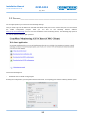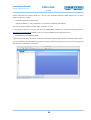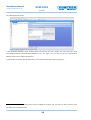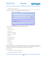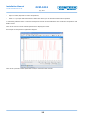
1
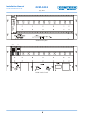
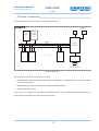
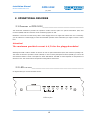
OCM-1012 Optical Communication
Mainframe
Installation Manual
July, 2013
Installation Manual
OCM-1012
IM-1307-OCM1012-EN-v1.odt
July, 2013
The following document is the property of Comtech Kommunikáció-Technológia Ltd. This document may only be
distributed to: (a) a Comtech Ltd employee having a legitimate business need for the information contained here,
or (aa) a non-Comtech employee having a legitimate business need for the information contained herein. No
license, expressed or implied, under any patent, copyright or trade secret right is granted or implied by the
conveyance of this document. No part of this document or the whole document may be reproduced, transmitted,
transcribed, stored in a retrieval system, translated into any language or computer languages, in any form or by
any means, electronic, mechanical, magnetic, optical, chemical, manual or otherwise without the prior written
permission of Comtech Ltd.
Comtech logo is the trademark of Comtech Ltd.
All products and service names are the property of Comtech Ltd.
Comtech Ltd. does not take responsibility for printing-errors.
Copyright © Comtech Kommunikáció-Technológia Ltd. All rights reserved.
2
Installation Manual
OCM-1012
IM-1307-OCM1012-EN-v1.odt
July, 2013
PRECAUTIONS
COMTECH Ltd. takes extremely care for making its products safe but improper use can cause risk of electrical
shock or fire. Comtech Ltd. does not take responsibility for improper use. Please observe the following instructions
to avoid accidents and failure of the device:
✔ Only qualified persons are allowed to install, manage and set the instrument.
✔ By working the equipment all the instructions about protection against electrical shock must be observed.
Please review the updated regulations of your country about this topic.
✔ Never use the equipment outdoors.
✔ Use the equipment only in room where power outlets with protective earthing are available.
✔ Do not remove the earthing wire while the instrument is connected to the telecommunication network.
✔ Make sure that power cables are not injured. Using the equipment with injured power cables is forbidden.
✔ Replace the defective fuse only with the same value.
✔ Repair only by manufacturer. Never remove the cover.
✔ Do not wear metal jewels or watch while using the equipment.
✔ Never touch the equipment by lightning.
✔ Always provide proper cooling for the equipment.
✔ The equipment should never exposed to moisture.
✔ Use UTP or STP cable for Ethernet connection to achieve proper work.
3
Installation Manual
IM-1307-OCM1012-EN-v1.odt
OCM-1012
July, 2013
Contents
1. GENERAL GUIDE............................................................................................. 5
1.1 Outside construction ........................................................................................................5
1.2 Inside construction ..........................................................................................................7
1.3 Technical specifications ...................................................................................................8
2. OPERATIONAL DESCRIBE................................................................................. 9
2.1 Operating of OCM-1012 ...................................................................................................9
2.2 LEDs on face ....................................................................................................................9
3. INSTALLATION AND OPERATION GUIDE...........................................................11
3.1 Mounting ........................................................................................................................11
3.2 Settings ..........................................................................................................................12
3.3 Accesible parameters ....................................................................................................15
4
OCM-1012
Installation Manual
IM-1307-OCM1012-EN-v1.odt
July, 2013
1. GENERAL GUIDE
ATTENTION!
The Optical Communication Mainframe (OCM-xxxx) contains optical
transmitters (FOT) and receivers (DROR). Avoid exposure to beam!
Shut down the transmitters before doing any modification on
device! Close connection of non-used cables with dust-protection
plug!
The OCM-1012 has been designed and developped for Comtech Ltd's Headend devices (transmitter and receiver).
The OCM-1012 cooperates with optical transmitters or receivers which can be fixed to frame with screws. Cooling
of optical devices are assured by coolers on back by creating a horizontal air-flow. OCM-1012 mainframes can be
put on top of each other. Rpm (Rotation per minutes) of coolers depends on temperature of devices in the frame.
You can connect the frame to the monitoring system. There is an opportunity to install a 2 nd power supply to solve
the redundant operation mode for transmitters and receivers.
Ordering information:
O
C
M
-
1
0
Accesories
1
2
Type
Covering sheet
Depends on empty slots OCM-CP1, OCM-CP3
Options
Required accesories
Without redundant operation
1 pc OCM-F cooler unit
Redundant operation
1 pc OCM-Power Supply
1.1 OUTSIDE
CONSTRUCTION__________________________________________
The mainframe is a standard 4-RU chassis with 12 slots for optical devices. LEDs on face give information about
the device's parameters. There is an RS232 serial port for service and settings tasks (see later). Right side on the
back there is the main Power Supply. On the left side there is the redundant Power Supply or cooler. On cooler you
can find an outside 24V powerplug. In the middle you can find an Ethernet (10BaseT) plug which assures the
contact to the monitoring system. There are LEDs for network-contact and datatraffic (LINK, ACT) and ALARM LEDs
(PWR, FAN, SUM).
5
Installation Manual
IM-1307-OCM1012-EN-v1.odt
OCM-1012
July, 2013
OPT1
OPT 2
RF1
RF2
REDUN
ALARM 1
ALARM 2
POWER
ENTER
DUAL RETURN PATH
OPTICAL RECEIVER
DROR
TP 1
-20dB
TP 2
-20dB
OCM-1012's face
D RO R
FO T
OCM-1012's back
6
OCM-1012
Installation Manual
IM-1307-OCM1012-EN-v1.odt
1.2 INSIDE
July, 2013
CONSTRUCTION_____________________________________________
On figure below you can see the Inside construction of OCM-1012.
STATUS
MONITORING
OCM-PS
OCM-PS
POWER
SUPPLY
POWER
SUPPLY
or FAN
1
2
LOCAL
ALARM
10BaseT
OCM-C
DC POWER BUS
MONITOR
and
CONTROL MODULE
RS485
ALARM
DROR
FOT
1
2
....
other
12
FRONT PANEL
LEDs
DB9
RS232
LOCAL PC
CONTROL and MONITOR
Inside contruction
The inside contruction is bus-system type with 3 parts:
–
DC POWER BUS: assures the power for optical devices. Depending on configuration one or two Power Supplies
can be joined to this line.
–
RS485: assures the inside communication regarding the RS485 standard.
–
ALARM: forwards the alarms.
These 3 parts are connected to the OCM-C controlmodule. LEDs on face, Ethernet plug and RS232 part are
connected to this module to assure the rack's right operation.
7
Installation Manual
IM-1307-OCM1012-EN-v1.odt
1.3 TECHNICAL
OCM-1012
July, 2013
SPECIFICATIONS__________________________________________
Power supply parameters
Maximal output power of power supply [W]
150
Maximal output current of power supply [A]
6,5
Internal supply voltage [VDC]
24
Input voltage range [VAC]
85-264
Type of fuse [A]
2
General parameters
Number of Module-slots [pcs]
12
Interface to the monitoring system
10BaseT or RS232
Internal communication
RS485
Temperature range [ºC]
0 … 50
Multiple error-indicator interfaces
NC-COM, NO-COM
Mounting width [mm]
428,6 (Standard 19”)
Dimensions [mm]
483x177x365
Weight [kg]
7,3
8
OCM-1012
Installation Manual
IM-1307-OCM1012-EN-v1.odt
July, 2013
2. OPERATIONAL DESCRIBE
2.1 OPERATING
OF
OCM-1012_______________________________________
The OCM-1012 mainframe provides the operation surface and the place for optical transmitters (FOT) and
receivers (DROR) and the connection to the monitoring system as well.
Mainframe comes out from the factory with 1 Power Supply which is on right side of back-view. If it is necessary
you can install a 2nd Power Supply to solve the redundant operation mode. Otherwise you ought to mount a cooler
here.
Attention!
The maximum provided current is 6,5A for the plugged modules!
Although the OCM is able to handle 12 devices in case of optical transmitters (FOT) the maximum quantity is 8.
The reason is the FOT's operation current (700mA). In case of return path optical receivers (DROR) you can use all
slots because DROR's current consumption is about 300-350mA. The RPM of coolers depends on temperature of
devices in rack. The coolers assure the optimal cooling and low noise-level.
2.2 LEDS
ON FACE_________________________________________________
On figure below you can see the LEDs on face.
LEDs on face
9
Installation Manual
IM-1307-OCM1012-EN-v1.odt
OCM-1012
July, 2013
LEDs are as follows:
–
PWR -> lights in case of Power Supply's failure. Example: redundant-power is not detected, power is low etc.
–
FAN -> lights if there is a problem with one of the coolers.
–
SUM -> lights in case of any problem independently of the rack's or device's failure.
–
P/C -> lights if there is a PC on RS232.
–
RX -> blinks if inside communication is in progress (receiving)
–
TX -> blinks if inside communication is in progress (transmitting)
–
ST -> blinks if there is no communication with any optical device.
On OCM-E module there is a plug with ALARM text with the following connections from left to right:
–
NC
–
COM
–
NO
If everything goes well (SUM LED is inactive) then NC and COM connectors are connected to each other by a relay.
If there is a problem (SUM LED is active) then relay switches over and makes connection between COM and NO
connectors (for example sound- and/or light warning signal).
10
Installation Manual
IM-1307-OCM1012-EN-v1.odt
OCM-1012
July, 2013
3. INSTALLATION AND OPERATION GUIDE
ATTENTION!
The Optical Communication Mainframe (OCM-xxxx) contains optical
transmitters (FOT) and receivers (DROR). Avoid exposure to beam!
Shut down the transmitters before doing any modification on
device! Close connection of non-used cables with dust-protection
plug!
3.1 MOUNTING_____________________________________________________
After unpacking please check the accessories. If everything is ok you can mount the mainframe. Fit the optical
transmitters and receivers into mainframe and fasten them with screws.
Attention! Non-used module-slots have to be covered with covering
sheets to assure the right cooling.
After you can connect the optical and RF cables. Watch out for the safety cap. Connect the monitoring server UTP
cable to the Ethernet socket and the power cables. Now you can switch the mainframe ON. If there are 2 Power
Supplies switch ON both.
11
OCM-1012
Installation Manual
IM-1307-OCM1012-EN-v1.odt
July, 2013
3.2 SETTINGS______________________________________________________
For the right operation you need to do the following settings:
First you need to give an IP address for OCM with the RS232 serial port on face. Connect this port to a PC and start
the
OCME
configuration
program
what
you
can
find
on
the
following
internet
address:
http://xx.xx.xx.xx/monitoring/ (xx.xx.xx.xx is the IP-address of the monitoring server). The following page opens if
you use the internet address right up before:
Choose the following link:
–
Download and run OCME config program
Running the configuration you need JAVA runtime enviroment. If everything goes well the following window opens:
12
Installation Manual
IM-1307-OCM1012-EN-v1.odt
OCM-1012
July, 2013
Set the right serial port (COM1, COM2, etc.), click on „Get” then MAC address of OCM appears. You can set IP
address for device in 2 ways:
–
automatic request from DHCP-server
–
using fix IP address -> over the address you can set the subnetwork and gateway
You can set also the number of Power Supply. Then click on „Set”.
If everything is done you can quit and start the MONITORING software by choosing the following link on
http://xx.xx.xx.xx/monitoring/ website (xx.xx.xx.xx is the IP-address of the monitoring server):
–
Download and run ComMonGui client
If password and username are correct (username: monitoring; password: supervisor) the following window opens:
You have to add the OCM to monitoring system to check its parameters. Right click on tree-structure's upper line
and choose the „Add Device” menupoint.
13
Installation Manual
IM-1307-OCM1012-EN-v1.odt
OCM-1012
July, 2013
The following window opens:
In the „Selecting new device type” window choose Comtech Ltd. from the „Vendor” list and choose the „OCM1012 Ethernet Optical Communication Mainframe” from the „Type” list. You have to set the communication
address which is the IP address of OCM-rack.
If everything is done then click OK. After that you can reach and check the rack's parameters 1.
1 You can add to list a new device from software version 2.9. In case of older version ask
for help from Comtech Ltd.
14
Installation Manual
OCM-1012
IM-1307-OCM1012-EN-v1.odt
3.3 ACCESIBLE
July, 2013
PARAMETERS____________________________________________
Click to „Devices parameters” on the right side than following window opens:
In „General” menu you can find data from OCM-1012. Data are as follows:
–
Device name
–
OCM firmware version
–
System uptime
–
Township (you can modify it)
–
Address (you can modify it)
–
Vendor name
–
Communication address
–
Enable/disable device
–
Comment
–
Map coordinate X
–
Map coordinate Y
Next part is „Modules” here you can configure the Power Supplies. „Power 1” is the working power supply you can
find this on the right side of rack seen from back-view. „Power 2” is the redundant power supply which is not
necessary but if it is not built in you have to install a cooler-module as written previously.
Other parameters:
–
Device's temperature (You can modify the limits)
–
Power Supplies values (working- and redundant)
15
Installation Manual
OCM-1012
IM-1307-OCM1012-EN-v1.odt
July, 2013
–
Rpm of coolers (depends on rack's temperature)
–
Other -> if you open this there will be a Status line where you can find information about operation
In monitoring software there is a Record menupoint. Records of OCM-mainframe are as follows: temperature and
RPM of cooler.
Click on the icon next to the selected parameter to display the record.
An example for temperature registration diagram:
Click on the „Records” button (left lower corner) to reach the other records.
16