1
Unit 1
Unit 2
Term. S3A
1
ON
Unit 3
Term. S3A
OFF
ON
Unit 4
Term. S3A
OFF
ON
Term. S3A
OFF
ON
OFF
or
Ethernet/BACnet (field syupply)
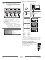
The wiring between the units must be performed
as shown on the wiring diagram and as shown in
the example below.
EKLONPG
Gateway
■
LonTalk® network (field supply)
Use shielded cables in case of a combination of
EKACPG with EKBNPG or EKLONPG.
Gateway
Examples of communication connections
NOTE
BMS
2
3
4
(*)
(*)
EKBNPG
(*)
≤500 m
Chiller unit 1
1 Setting of the S3A DIP switch on the PCB
2 Terminal on the address card (connect to + and – of RS485)
3 Ferrite core (wind the cables 2 times)
Address 01
■ = DIP switch setting
(*) Connect the shielding of the wires to each other
■
■
Make the RS485 +/– connection for Modbus
communication using a shielded 0.75~1.25 mm 2
2-wire cable (maximum of 500 m from EKLONPG
or EKBNPG to connection on last unit in line).
Modbus slaves
4 Up to EKBNPG or EKLONPG +/– terminals of the RS485 Modbus
communication
A11P
S3A
ON
OFF
Chiller unit 2
Address 02
A21P
A11P
S3A
ON
OFF
Chiller unit 3
A21P
Main specifications
Power supply
Relative humidity
Operating temperature range
Storage temperature
Power consumption
Weight
Maximum fuse amps
1N~ 230 V AC (50 Hz)
5~90%, non-condensing
–10~43°C
–20~70°C
10 W maximum
2.1 kg
6A
Address 03
Gateway
Gateway
Modbus slaves
Modbus slaves
Chiller unit 1
Chiller unit 1
Address 01
Address 01
network
network
field supply
field supply
A11P
S3A
ON
OFF
In these examples, the S3A DIP switch on the address card of chiller
units 1 and 2 must be set to OFF. Because chiller unit 3 is the last unit
in line, the S3A DIP switch on the address card must be set to ON.
Connecting the field supplied wiring
Pull the wires inside the option box through the screw
nuts and close the nuts firmly in order to ensure a
good pull relieve and water protection.
An additional pull-relief is required, strap the cables
with a tie wrap (field supply).
Installation manual
3
EKLONPG + EKBNPG
Gateway option box
4PW40333-1A