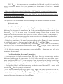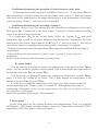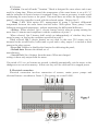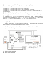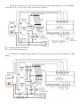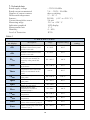
1
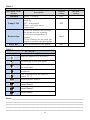
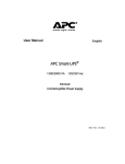
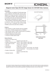
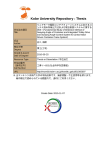
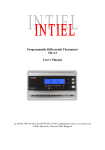
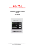
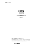
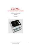
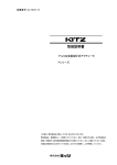
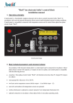
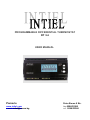
PROGRAMMABLE DIFFERENTIAL THERMOSTAT
DT 3.4
USER MANUAL
Pomorie
www.intiel.com
e-mail: [email protected]
Peter Beron 9 Str.
fax:0596/32580
tel. 0596/33366
2
TECHNICAL DESCRIPTION
1. Application
Differential thermostat is integrated in systems for preparing domestic hot water
into boilers, heated by combination by boiler, solar panels and electric heaters. Designed
to manage the work of two circulation pumps installed in:
- Water circuit between the panels and serpentine the water tank;
- Water circuit between the boiler and the second serpentine of the water tank.
In this way regulate heat exchange therebetween.
It is possible to include a third pump to regulate the heat exchange between the
solar panels and a second tank (buffer tank or pool).
2. Operation
The thermostat has four temperature sensors mounted respectively in the heater,
solar panels and boiler. The process works with the following parameters:
2.1 dT1, Δt1 - set and actual temperature difference between the panel and the
boiler. dT1 can be set within the range of 2 to 20 °C. The default setting is 10 °C;
2.2 dT2, Δt2 - set and actual temperature difference between the boiler and the
heater. dT2 can be set within the range of 2 to 20 °C. The default setting is 10 °C;
2.3 Tbset - set temperature in the heater to which it could reasonably be heated by
solar panels, boiler, electric heaters. Set in the range of 25 to 90 °C. The default setting
is 60 °C;
2.4 Tbmax - critical maximum temperature in the heater. Set in the range from 80
to 100 ° C. The default setting is 95 °C;
2.5 Tbmin - minimum water tank temperature below which the defrost is terminated
on the panel. Do not set. The default setting is 20 °C;
2.6 Tpmin - minimum temperature of the solar panel. Set in the range from 20 to
50°C. The default setting is 40 °C;
2.7 Tpmax - maximum permissible temperature of the solar panel. Set in the range
from 80 to 110°C. The default setting is 105 °C;
2.8 Tpdef - defrosting temperature of the solar panel. Set in the range from -20 to
10 °C. Default without defrosting - -;
2.9 Tkset - boiler water temperature at which the pump 2 will turn without
monitoring differential (only if the corresponding option is selected). Set in the range from
30 to 90 °C. The default setting is 60 °C;
2.10 Tkmin - minimum boiler water temperature. Set in the range from 20 to 50
°C. The default setting is 40 °C;
2.11 Tkmax - maximum boiler water temperature. Set in the range from 80 to 100
°C. The default setting is 95 °C;
2.12 Tkdef - temperature of the boiler water, under which is turn a pump 2
continuously the purpose to prevent freezing of the water in the pipes. Do not set.
The default setting is 10 °C;
3
2.13 Tbuff - Set temperature to a second tank (buffer tank or pool) It is used only
when it is selected Heaters Opt.3 (see point 4.2). Set in the range of 25 to 90°C. Default
40 °C.
- When any of the temperatures higher than +120° C and is not connected temperature
sensor of the display shows "hi"
- When one of the temperatures is lower than -20 °C or has a bridged temperature sensor
is displayed on the display "low"
The operation of the thermostat is defined according to the status of the sensors as follows:
А) Normal modes
Conditions defining the operation of pump 1:
- At a temperature in the lower part of tank Tb1 lower than the set Tbset and positive
difference Δt1 between the temperature Tp of the panel and the bottom heater, more than
the set dT1 by 2 °C, is turn a pump 1 is carried heating of heater from the panel. If in
the process of heating the boiler Δt1 equals the set dT1, turns off pump 1 (relay output 1)
- The heating is done until the temperature at the bottom of the tank Tb1 equals with set
Tbset, then the pump is switched off;
- If the above conditions of the panel temperature drops below Tpmin, the pump operation
is prohibited, however, that there may be Δt1> dT1 +2 °C and Tb1 <Tbset;
- If the temperature of the solar panel drops below Tpdef, pump 1 turn on enforcement,
although it was off because of temperatures below Tpmin (only if option enabled for
defrosting);
- If the previous regime tank temperature drops under Tbmin, the pump turns off, as is
terminated defrost panel.
Conditions defining the pump 2 operation:
- At a temperature in the lower part of tank Tb1 lower than the setpoint and a positive
difference Δt2 between the temperature Tk of the boiler and the lower part of the heater,
more than the set dT2 by 2 °C, turn on a pump 2 and is carried to the heating heater from
the boiler. If in the process of heating the heater Δt2 declining, after Δt2 align the set dT2
turn off the pump (relay output 2);
- The heating is done until the temperature at the bottom of the tank Tb1 equals with
setpoint Tbset, then the pump is switched off;
- If the above conditions, the boiler drops below Tkmin, the pump operation is turn off,
however, that there may be ∆t2>dТ2+2° C and Тb1<Tbset;
- If the boiler temperature drops below Tkdef, pump 2 is force, although it has been
turned off because of temperatures below Tkmin.
4
Conditions determining the operation of electric heaters on the tank:
- If the temperature at the top part of tank Tb2 is lower by 15 °C than the set Tbset is
allowed heating by electric heaters to reach the Tbset (relay output 3). Does this happen
when there are no conditions for the pumps and heaters to work independent of the pump,
select the option "Heaters" in the menu (see section 4.2).
Conditions determining the operation of pump 3:
- With option Heaters Opt.3 (see section 4.2), the controller is configured to work with a
third pump that is connected to the relay output 3 instead of electric heaters and Tb2
sensor is mounted in the second tank
- At a temperature Tb2 in the second heater below the setpoint Tbuff and panel
temperature Tp, as well as a positive difference Δt1 between the temperature Tp of the
panel and the first heater, larger than the set dT1 by 2 °C, turn on a pump 3 . But only in
cases where there is no running another pump (pump 1 and pump 2 is stopped);
- Heating is performed while the temperature Tb2 equals the set Tbuff, then the pump is
switched off;
- If the conditions for their turn on of pump 1 and / or pump 2, work pump 3 is
terminated.
In this way the heating of the first heater is given priority.
B) Alarm Modes
- If in the process of heating the heater, the temperature of the panel exceeds Tpmax,
pump 1 will be forced the purpose cool the panels. This is done despite the temperature at
the bottom of the tank Tb1 can exceed Tbset.
- If in the process of heating the heater, the temperature of the boiler exceeds Tkmax,
pump 2 is force for cooling of the boiler. This is done despite the temperature at the
bottom of the tank Tb1can exceed Tbset.
- If, at the above conditions temperature in the lower part of the heater reaches the
critical maximum value Tbmax, pump 1 is turned off, although this may result to
overheating of the panel. In this way the temperature in the boiler has a higher priority to
the temperature of the panel.
In this case operation of the pump 2 also terminate.
3. Front panel
On the front panel are the control elements and programming. These are graphical
LCD display, LED display and three buttons - button up, button down and button "SET".
Appearance of the front panel is shown in Figure 1.
5
Figure.1
3.1 Graphic LCD display with a resolution of 128x64 pixels (1) - provides information
on the current temperature measured by the sensors Figure 1.1a, state information system
shown by icons fig.1.1b (see Table 3) Ability to adjust the controller by user menu
fig.1.1c;
Figure 1.1a
3.2 LED (2) - indicates abnormal conditions;
3.3 Buttons (3) - buttons to adjust the controller.
4. Programming
After power supply the thermostat automatically established reset, which shows the
temperature the tank, solar panel and boiler and system status by icons.
4.1 Enter the menu of the controller
By pressing and holding the "SET" button for more than 3 seconds.
With the up and down to navigate forwards and backwards in the menu. Change the
selected item by pressing of a button SET. A when the value is changed after pressing the
button SET value start flashing, changing it is done by pressing up or down. Confirm the
selected value - again with SET.
6
4.2 Options
- Vacation. On and off mode "Vacation." Mode is designed for cases where tank is not
used for a long time. When activated, the temperature of the water heater is set at 40 ° C
and the inclusion of electric heaters is terminate. Pump 1 turns as necessary in order avoid
overheating the water heater or the panel. This mode does not affect the operation of the
pump 3, where the controller is used with the selected option - Heaters Opt.3;
- Pump 2 ON. With option dT2, management of pump 2 becomes differential
temperature between the water heater and the boiler. With option Tkset, pump 2 turns
following an assigned temperature, without monitoring the differential difference;
- Heaters. When selected, Opt.1, electric heaters switch when no pump running for
more than 15 minutes and compliance with the conditions of point 2.
When selected, Opt.2 heaters shall switch on independently of whether they have
turned a pump, as long as the conditions specified in point 2.
When selected Opt.3 electric heaters are not used. In this case Tb2 sensor can be
mounted in the second boiler, buffer tank or pool and to relay output 3 to include a third
pump to the solar system;
- Freez Def. Enables or disables the function for defrosting the panel;
- Default data. Returns the default set of
manufacturer;
- Save & Exit. Save Settings from the menu. When not changed
settings is done only output from the menu.
If a period of 15 sec. no buttons are pressed, it should automatically exit the menu, as the
changes are not saved in memory. In this case they will be valid until it is stopped power.
5. Electrical connection
Electrical connection involves connection of sensors, mains power pumps and
electrical heaters, according to Figure 2. The sensors are a type Pt1000 .
Figure 2
2222
7
If necessary connecting cables of the sensors can be prolonged.
Recommended length that does not affect the measurement is to 100m.
Terminals 16, 17 are input to the sensor in the solar panel.
Terminals 18, 19 are input to the sensor at the bottom of the water tank.
Terminals 20, 21 are input to the sensor on top of the water tank or secand water tank or
swimming pool.
Terminals 22, 23 are input to the sensor in the boiler.
Terminals 1 ÷ 4, 5 ÷ 8 and 9 shall be conected accordingly protective ground zero phase
power supply.
At terminals 10, 12 and 14 are respectively connected to pump 1, pump 2 and the
electrical heaters, which starting phase (L1, L2 and L3). At terminals 11, 13 and 15 out
phase (L1, L2 and L3), when terminals 10, 12 and 14 not out and vice versa.
6. Hydraulic connection
Example of a system with one heater, system with 2 tank (buffer tank, swimming
pool). Heated by solar panels, boiler and electrical heaters.
A) Heatingt water tank with boiler, solar panels and electric heaters. With a common
pump tank and heating.
PT - working heater thermostat
BT - block heater thermostat
8
B) With two pumps for water tank and heating. Rather than pump 2 can be installed
solenoid valve or a two-way valve with motor actuator:
PT - working heater thermostat
BT - block heater thermostat
C) Heating a second heating boiler, electric instead electric heaters mounted a third
pump:
9
7. Technical data
Rated supply voltage
Rated current commutated
Number of output contacts
Differential temperature
Sensors:
Current through the sensor
Measuring range
Indication graphical
Measurement unit
Humidity
Level of Protection
~ 230V/50-60Hz
7A / ~ 250V / 50-60Hz
three switching
2 ° - 20 ° C
Pt1000 (-50 ° to +250 ° C)
2,6 mA
-20 ° to +120 ° C
LCD display
1°C
0 - 80%
IP 20
Table 1
PARAMETERS
indication on
the display
dT1
dT2
Tbset
Тbmax
Tbmin
Трmax
Трmin
Тpdef
Тkset
Тkmax
Тkmin
Тkdef
Tbuff
description
Setpoint the temperature
difference between the panel
and the water tank.
Setpoint the temperature
difference between the boiler
and the water tank.
Setpoint water tank temperature
to which it can normally be
heated by solar panels and
boiler
Critical maximum temperature
in the heater.
Minimum water tank
temperature below which the
defrost is terminated on the
panel.
Maximum temperature of the
solar panel.
Minimum temperature of the
solar panel.
Temperature at which defrost
allows the solar panel.
Setpoint boiler water
temperature to which is
operated pump 2
Maximum boiler water
temperature
Minimum boiler water
temperature
Protective boiler temperature
below which turn on a pump 2
Setpoint temperature for the
buffer or pool (only used when
- Heaters Opt.3)
10
range
default setting
2 ÷ 20°С
10° С
2 ÷ 20°С
10° С
25 ÷ 90° С
60° С
80 ÷ 100°С
95° С
not set
20° С
80 ÷ 110°С
105° С
20 ÷ 50° С
40° С
-20 ÷ 10°С
--
30 ÷ 90°С
60° С
80 ÷ 100°С
95° С
20 ÷ 50° С
40° С
not set
10° С
25 ÷ 90° С
40° С
the user
setting
Table 2
OPTIONS
indication on the
display
Vacation
Pump 2 ON
Heaters Opt.
Freez Def.
description
Mode "Vacation."
The turn on of the pump 2 will be
made by:
dT2 - differential;
Tkset - set boiler water
temperature.
1) electric heaters turn on when
the pumps are not working;
2) are turn on regardless of
pumps;
3) Opt3-heaters are not used, the
output is used for the third pump.
Frost protection of solar panels
default
setting
OFF
the user
setting
dT2
Opt.1
OFF
Table 3
image
ICONS
description
Function antifreeze is activated
Overheating of the solar panel
The temperature in the tank is above
the maximum
Temperature in the boiler is above the
maximum
The temperature in the boiler is
below 10 ° C
turned electric heaters
turned Pump 1
turned Pump 2
turned Pump 3
Notes:________________________________________________________
____________________________________________________________
____________________________________________________________
____________________________________________________________
____________________________________________________________
11
____________________________________________________________
____________________________________________________________
____________________________________________________________
____________________________________________________________
____________________________________________________________
____________________________________________________________
____________________________________________________________
____________________________________________________________
____________________________________________________________
____________________________________________________________
____________________________________________________________
____________________________________________________________
7. Warranty
The warranty period is 24 months following the purchase date of the unit or its
installation by a qualified staff, but not exceeding 28 months after the production date.
The warranty is extended to the malfunctions that occur during the warranty period and
are result of the production reasons or defective used parts.
The warranty does not relate to malfunctions corresponding to not-qualified
installation, activities directed to the product body interference, not regular storage or
transport.
The repairs during the warranty period can be done after correct filling of the
manufacturer warranty card
12