1
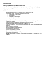
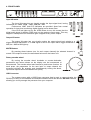
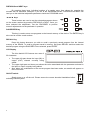
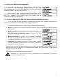
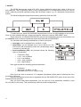
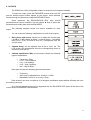
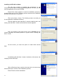
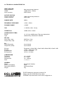
USER MANUAL
User Manual Contents
1. IMPORTANT REMARK
04
2. INSTALLATION
05
3. INTRODUCTION
06
4. FRONT PANEL
07
5. REAR PANEL
09
6. THE MAIN MENU
10
7. INPUTS
12
8. OUTPUTS
13
9. SOFTWARE
15
10. TECHNICAL CHARACTERISTICS
24
All numbers subject to variation due to production tolerances. ECLER S.A. reserves the right to make changes or
improvements in manufacturing or design which may affect specifications.
3
1. IMPORTANT REMARK
Congratulations! You are the owner of a carefully designed and manufactured equipment. We
thank you for trusting in us and choosing our DP400 processor.
In order to get the optimum operation and efficiency from this unit, it is VERY IMPORTANT
- before you plug anything - to read this manual very carefully and bear in mind all considerations
specified within it.
We strongly recommend that its maintenance be carried out by our Authorised Technical
services.
Precautions
This apparatus must be earthed through its mains cable.
Do not expose the unit to rain or water splashes, and do not place liquid containers or
incandescent objects like candles on top of the unit.
Should any connection / disconnection task be done, always disconnect the unit from the
mains supply.
There are no user serviceable parts inside the unit.
Ground Loops
Care should be taken, so that the different mechanical and electrical grounds, as well as the
chassis and ground connections arriving to the device, to be independent from each other.
Ground loops can be easily detected through a low frequency hum noise (50Hz). Depending on
the level of this noise, it can interfere on the music quality.
Audio connections
Usually, many people do not care enough about the quality of cables. Many times, because of a
bad connection or bad quality cables, there can be important problems during the music reproduction.
Cleaning
The control panel must not be cleaned with any dissolvent, abrasive or petroleum derived
substance else paint and silk-printing could be damaged. Whenever cleaning should be necessary use a
soft cloth slightly wet with water and neutral liquid soap. Be careful that no liquid gets into the unit
through its orifices. Never use sharp or erosive objects to scratch the control panel.
4
2. INSTALLATION
The DP400 can be mounted in a standard 19” rack (482.6 mm) taking up one height unit
(44 mm).
For professional use it is recommended to place the processor in the same rack as the power
amplifiers.
Given the small power consumption of the unit, no ventilation is required. Nevertheless, it is
advisable not to expose the unit to extreme temperatures as well as ensure a dry and dust-free operating
environment.
It is important not to place the processor next to electrical noise sources such as transformers,
voltage dimmers, motors, etc. or their mains supply cables. The metal cover of the device should never
be removed under any circumstance for that same reason.
The DP400 operates with alternate current (AC) between 90 and 264V at 47 to 63Hz. This device
features an oversized power supply which adapts itself to any mains voltage around the world, without
the need of manual adjustment.
Even though the noise produced by powering up is minimum, it is always advisable to follow this
power up sequence: signal sources, mixing unit, processor and, finally, power amplifiers. The power
down sequence must follow exactly a reverse order. By closely following this sequences, all peaks or
transients produced by switching on and off devices do not affect the next devices in the chain and, of
course, never reach the loudspeakers, which are extremely sensitive about this.
5
3. INTRODUCTION
DIGITAL LOUDSPEAKER SYSTEM PROCESSOR DP400
The ultimate solution for comprehensive adjustment and control of complex loudspeaker systems
with remote control using the DP:lab2 software. Excellent audio quality and dynamics. The DP400 uses
high quality Σ-Δ type AD/DA converters.
Main features:
•
•
Superb audio quality thanks to its 24-bit DSP and its 48kHz sampling rate.
2 inputs and 6 outputs. Includes the following operating modes:
o x-over 2x2 way + 1 extra output
o 2x3 way stereo
o x-over 4 way + 2 extra outputs
o x-over 5 way + 1 extra output
o x-over 6 way
o All inputs and outputs muted
•
Selectable Crossover slopes of 6,12,18,24 or 48dB per octave and filter types: Butterworth,
Linkwitz-Riley or Bessel.
Parametric or shelving equalizer for a smooth system frequency response.
Input and channel gain adjustment range from -40 dB to +12 dB.
Limiter and compressor. Limiter/compressor output, attack and release times with adjustable
threshold.
Phase invert option per channel.
Electronically balanced inputs and outputs.
Up to 682 ms signal delay per input.
Up to 21 ms signal delay per channel.
30 memory bank locations for user programs.
Password-controlled safety lock and data protection system.
2x20 character blue backlit LCD.
DP:lab2 control software to configure and programme all parameters of the DP400 unit over a
USB port.
•
•
•
•
•
•
•
•
•
•
•
6
4. FRONT PANEL
Input VU-meter
The input VU-meter lets you visually monitor the input signal level, having
indications for –30dB, -24dB, -12dB, -6dB and –3dB.
Furthermore, LIMIT and CLIP indicators are provided. Apart from normal
operation for input level monitoring, digital clipping is also shown here.
If the CLIP led lights up but the LEDs below do not, this means that the
digital audio signal is clipping (DSP) and not the analogue input stage. This may
happen if inadequate EQ or excessive gain is applied to any of the outputs.
Output VU-meter
The output VU-meter lets you visually monitor the output signal level relative to a
trigger threshold adjustment. If a +4dB signal is sent to an output with a trigger threshold of
0dB, the –6dB led will light up.
MUTE Buttons
By pressing these buttons (one for each output channel) the selected channel is
muted. If the output is muted, the associated led next to the button is lit.
Rotary encoder wheel
By turning the encoder wheel clockwise or counter-clockwise,
parameters and values shown on the display can be incremented or
decremented. The encoder wheel also features a push-button function. At
each press, the parameters for the next input or output channel are
accessed cyclically. By pressing and simultaneously turning the wheel,
inputs and outputs can be accessed more quickly.
USB Connector
The system comes with a USB B-type connector that is used to communication the
DP400 up to the PC and establish a connection between the DP400 and the DP:lab2 software,
allowing you to fully manage the processor from your computer.
7
PREVIOUS and NEXT keys
By pressing these keys, individual settings of a certain menu item chosen by pressing the
encoder can be accessed. Example: If you are in the PROGRAM screen, PREVIOUS and NEXT will
lead you to the individual adjustable parameters inside the PROGRAM menu.
◄ and ► keys
These buttons are used to set the selected parameter shown
on the screen reached by pressing PREVIOUS or NEXT. Once you
have selected the adjustment, use the ENCODER to perform
numeric adjustments on the parameter in question.
SAVE/ENTER key
This key is used to store new programs to the internal memory of the device. The ENTER key is
also used to confirm certain actions.
RECALL Key
Press this button whenever you wish to recall a previously saved program from the internal
memory of the DP400. To recall a program stored in memory, first press RECALL and then select the
desired program using the ENCODER. Once selected, press ENTER.
LCD Display
The blue backlit LCD features two rows of
20 characters.
•
•
•
The upper left part shows the input (IN) or
output (OUT) channel currently being
edited.
The upper right part and lower part shows the value associated with the parameter selected in
the input or output currently being edited.
Also, when any modification to the current program has been made, an asterisk will appear on
the LCD screen.
ON-OFF switch
Simply turns on or off the unit. Please ensure the correct electrical installation before
switching ON the system.
8
5. REAR PANEL
The rear panel features following connections:
Mains socket
The DP400 features a 3-pin IEC socket for mains supply. The fact of having a switched mode
power supply, allows the use of a wide range of mains specifications: from 90 to 264 VAC at frequencies
between 47 and 63 Hz. Before switching on the unit, please ensure that the DP400 is connected to earth
and that the electrical installation fulfils the local safety regulations.
Input Connectors (CH1, CH2) and Output Connectors (Output 1-6)
The DP400 has two inputs (CH1 and CH2) on three-pin female XLR sockets. The pin layout is
following: Pin 1 is Ground, Pin 2 is +signal (hot) and Pin 3 is –signal (cold). The six outputs of the DP400
(OUTPUT 1-6) are on three-pin male XLR sockets. As in the input connectors, Pin 1 is Ground, Pin 2 is
+signal (hot) and Pin 3 is –signal (cold).
9
6. THE MAIN MENU
From the MAIN MENU, you can manage functions and parameters like:
•
•
•
Selecting the preset or operating mode (PROGRAM submenu)
Loading, storing and deleting configurations stored in the processor’s internal memory
(PROGRAM submenu)
Security options (use a password to block the processor) (SECURITY submenu)
To call up the main menu, press the ENCODER several times until MAIN MENU appears.
The following diagram shows the main menu and each of its submenus:
6.1. LOAD PRESET MENU: CONFIGURING THE OPERATING MODE
The DP400 allows the following operating modes:
1. x-over 2x2 way + 1 extra output
2. 2x3 way stereo
3. x-over 4 way + 2 extra outputs
4. x-over 5 way + 1 extra output
5. x-over 6 way
6. All inputs and outputs muted
Once installed and switched on, the unit should be configured in order to
choose the operating mode (preset). For this, you must:
• Press the ENCODER several times until MAIN MENU –
PROGRAM appears on the screen.
• Press ENTER. The preset selection submenu, LOAD PRESET,
will appear.
• Press ENTER again to display the 6 operating modes, which are
easy to choose by turning the ENCODER. Press ENTER to load
the desired operating mode. The processor is now ready for you
to configure its inputs and outputs (see the INPUTS and
OUTPUTS sections below).
10
6.2. RECALLING AND STORING PROGRAMS
Once you have selected the operation mode, you may recall,
store and delete up to 30 different programs in the unit. To do so, from
the PROGRAM menu, use the PREV/NEXT keys to switch between the
programs as desired and then press ENTER.
Every program has a numbered position in the memory of the
processor. It is easy to select this position using the ENCODER. When it
has been selected, press ENTER and the program will be
recalled/stored/deleted, as indicated.
6.3. SECURITY MENU PROTECTING THE DP400 FROM OUTSIDE MANIPULATION
It is a good idea in some applications to protect the processor from unwanted manipulation by
others that could affect its configuration or the programs stored in it.
The DP400 includes 4 types of safety locking, which are described below:
•
Modify: the data may be seen but cannot be modified. The input and channel MUTE functions
remain active.
•
Modify and view: the data may be not be seen or modified. The
recall and storage of programs in memory is blocked. The input
and channel MUTE functions remain active.
•
Modify and MUTE: this option is similar to “Modify”, except that
the input and output MUTE functions are also blocked. The recall
and storage of programs in memory is blocked.
•
Everything: the parameter values may not be seen or modified.
The MUTE function is also blocked. The recall and storage of
programs in memory is blocked.
After you have selected the desired safety lock type using the ENCODER, press ENTER. The unit
will then ask you for a password. The password may contain up to 8 characters. These may be
selected using the ENCODER.
The DP400 is initially delivered without a password.
WARNING: it is very important to keep your password in a safe location. It cannot be
recovered if forgotten or lost.
11
7. INPUTS
The DP400 features two inputs IN A, IN B, and an additional internal input, which is the mix of
both channels. This is especially useful in mono configurations or in configurations where you need to
send a channel processed separately along with the stereo outputs, e.g. in a subwoofer reinforcement
system.
The following diagram shows the processing menus for IN A and IN B:
To select an input, press the ENCODER several times until IN A or IN B appears on the screen.
Once you have selected the input, browse through the submenus using the PREV/NEXT keys.
Some submenus, like EQUALIZATION (EQ), have several parameters than can be modified. Use
the ◄ and ► keys to select the parameter and modify them with the ENCODER.
You can make the following modifications to each of the inputs:
•
•
•
Input gain: can be adjusted from -40 dB to +12 dB.
Input delay: can be adjusted from 0 ms to 682.52 ms. The
LCD screen will automatically show the corresponding values
in metres (m) and feet (ft).
Input equalization (EQ): the processor allows the following
types of equalization
o
o
o
o
o
Parametric (Peq)
Lo12 – Low 12 dB/oct
Lo6 – Low 6 dB/oct
Hi12 – High 12 dB/oct
Hi6 – High 6 dB/oct
Each type includes the following general parameters:
o
o
o
Frequency
Gain (from -30 dB to +15 dB)
Bandwidth from 0.01 to 4 (only in Peq)
Each input can have a maximum of 6 assigned equalization points without affecting the unit’s
processing resources.
All of the equalization points can be bypassed with the EQ ON/EQ OFF option at the start of the
EQUALIZATION submenu.
After you have made these adjustments, you can copy all of the parameters modified in input
IN A to IN B (or vice versa). This is particularly useful for stereo configurations.
12
8. OUTPUTS
The DP400 has 6 fully configurable outputs or channels for increased versatility.
To select an output, press the ENCODER several times until OP
and the desired output number appear on the screen. Once selected,
browse through the submenus using the PREV/NEXT keys.
Some submenus, like EQUALIZATION (EQ), have several
parameters than can be modified. Use the ◄ and ► keys to select the
parameter and modify them with the ENCODER.
The following diagram shows the menus available for each
output:
You can make the following modifications to each of the outputs:
•
Gain, phase and source: allows you to adjust the channel gain
(-40 dB to 12 dB), phase (in phase + or out of phase, -) and which
input (IN A, IN B, IN A+IN B and OFF) corresponds with the
current output.
•
Channel delay: can be adjusted from 0 ms to 21.31 ms. The
LCD screen will automatically show the corresponding values in
metres (m) and feet (ft).
•
Channel equalization (EQ): the processor allows the following
types of equalization
o
o
o
o
o
Parametric (Peq)
Lo12 – Low 12 dB/oct
Lo6 – Low 6 dB/oct
Hi12 – High 12 dB/oct
Hi6 – High 6 dB/oct
Each type includes the following general parameters:
o
o
o
Frequency
Gain (can be adjusted from -30 dB to +15 dB)
Bandwidth: from 0.01 to 4 (only in Peq)
Each channel can have a maximum of 4 assigned equalization points without affecting the unit’s
processing resources.
All of the equalization points can be bypassed with the EQ ON/EQ OFF option at the start of the
current output’s EQUALIZATION submenu.
13
•
High pass filter/low pass filter: allows you to adjust the frequency, type of filter (Bessel,
Butterworth and LR) and the slope by octave (12 dB, 18 dB, 24 dB and 48 dB) of the high-pass or
low-pass filter needed for the channel selected.
•
Limiter/compressor: allows you to adjust the threshold (-20 dBV to 10 dBV), level of
compression (1.2 to inf.), attack time (from 0.5 ms to 50 ms) and release time (from 10 ms to 1 s).
Proper adjustment of the limiter/compressor can be very important in the event that the
loudspeakers need to be protected against signal clipping or an excess of power.
When an amplifier receives an input level higher than its nominal input level, the input stage can
become saturated, resulting in an amplified clipped output signal. This clipped signal has a strong DC
voltage component that can easily damage the loudspeakers.
To avoid this, the limiter/compressor should be adjusted to avoid saturation of the amplifier in
order to prevent damage to the loudspeakers.
On the other hand, if the amplifier has a larger power output than the loudspeakers can handle or
the system must operate during long periods at full power, the limiter/compressor must be adjusted such
that the signal delivered by the amplifier does not damage the speakers.
The limiter threshold level also serves as the reference for the output VU-meter, such that the
levels displayed always bear relation to the adjusted limiter threshold. For example, if the limiter is set to
2.0 dBV, the LIMIT indication on the output VU-meter will be +2 dBV higher, as follows:
VU-METER
Limit
-3dB
-6dB
-12dB
OUTPUT LEVEL
+2,0dBV
-1dBV
-4dBV
-8dBV
After you have made these adjustments, you can copy all of the parameters modified in one
channel to another. This is particularly useful for stereo configurations.
14
9. SOFTWARE
DP:lab2 software
The DP400 processor works together with the DP:lab2 software which allows the
remote configuration of all device parameters from a standard PC or laptop with following
specifications:
-
Intel P3 processor or equivalent at 600 MHz.
256 Mbytes of RAM memory.
Windows 98 SE, XP Home, XP Professional, Windows 2000 or Vista operating system.
With the use of this software application, the operating mode, the crossover filters and the input
and output equalizations can be configured in the same aspects as would be done from the unit itself.
The communication between the PC and the DP400 unit is done with a USB cable.
It is important to keep in mind that when using DP:lab2 to manage the DP400, the controls on the
front panel of the unit will be disabled and the LCD screen will say REMOTE CONTROL.
15
Installing the DP:lab2 software
The first step consists of installing the programme on the
computer that will serve as the programming platform. For this, you will
use the application file on the CD-ROM.
Execute this setup program to start the installation process by
double-clicking on the icon. Following screen welcomes the installation
process and invites you to continue.
Click on the Next > button. The following screen now asks you
for the application installation directory.
Once the path has been selected (in case the default path is not
used), press the Next > button so that the next screen appears.
Here, the position of the direct access icon for DP:lab2 can be
chosen. Normally, the default position is a good choice. Pressing the
Next > button.
On this screen, you have the option to create direct access
links.
Immediately after the Next > button is clicked on this screen, the
copying process will begin.
After all files have been copied to the hard drive, the last screen
informs about the success of the installation process.
Press Finish to exit the installation.
16
Installing the drivers
Check that the DP400 USB cable is disconnected and start your computer. Run Driver
installer.exe program form the “Drivers” folder on the CD.
If this method is not compatible with your computer, connect the USB cable first and when the
system will ask for the driver files, tell the complete path of the "Drivers" on the CD-ROM.
To check the proper installation, go to “Device Manager”. The mixer should appear under:
"Prolific USB-to-Serial Comm Port (COM?)".
Take note of the automatically assigned COM port number.
17
Double-clicking on this icon executes the application, so that all parameters can be adjusted.
Following main screen appears.
Before pressing “CONNECT”, assign the same
COM port number that was assigned to the drivers. To
change it, use the "CONFIG → RS232" menu.
18
9.1. DP:lab2. DESCRIPTION
DP:lab2 is a graphic interface that makes it easier and more comfortable to manage the DP400
than with the controls on the front panel of the unit.
Connecting the DP400 to the computer
Use the USB cable provided with the DP400 to connect it to your PC or laptop computer. Then,
click on the corresponding icon to start up DP:lab2. The DP:lab2 start screen will appear on the screen.
Press CONNECT (on the upper left side of the screen) to initiate communication between the computer
and the unit.
If the DP400 is not working properly or the USB cable is not connected
correctly, the following message will be displayed in DP:lab2:
If this is the case, double-check the USB connection and make sure
the DP400 is working.
After completing these steps, you are ready to modify the input and
output parameters and operating modes (presets), recall and store configurations in the DP400 and PC,
and apply the desired password-protected safety lock, all from your computer.
Disconnecting the DP400 from the computer
After you have finished using DP:lab2 with the DP400 connected to the computer, you must
deactivate the virtual CONNECT button on the upper left-hand side of the screen. Then, disconnect the
USB cable from the DP400.
The following is a description of the main menus and submenus in DP:lab2.
9.2. PROGRAM AND CONFIG MENUS
In the upper left-hand side of the screen, DP:lab2 has two menus that are used primarily to
manage PC-to/from-DP400 communications, select the operating mode (presets), put a lock on the unit,
and manage the storage and recall of configurations from the DP400 and PC.
CONFIG MENU – RS232 (USB)
DP:lab2 allows you to choose the serial communication port used in the USB connection with the
unit.
19
CONFIG MENU – PRESET
This option allows you to choose the operating mode (preset) for the
DP400. See section 6.1 for further information about the available operating
modes.
The stereo operating modes (numbers 1 and 2) include the possibility of
working in stereo link. With a stereo link, all of the parameters modified in one
channel (input or output) are automatically copied and updated in another
associated channel.
The following parameters are not copied, even if the stereo link operating
mode is active:
•
•
•
Output selected to go with a particular input
MUTE status of an input or output
Phase invert status of an output
E.g.: When the 2x3 WAY CROSSOVER is activated with the stereo link option, the inputs and
output channels will automatically be grouped as follows:
Inputs: IN CH1&IN CH2
Outputs (channels):
•
•
•
Low: Out1&Out4
Mid: Out2&Out5
High: Out3&Out6
CONFIG MENU – COPY DATA
With the copy data option, you can copy all the parameters from one
input to another or from one output or channel to another.
This option is especially useful in mono operating modes where each of
the outputs should have the same parameters as all the others.
CONFIG MENU – LOCK/UNLOCK
Selecting this option calls up a window that allows you to select the lock type
and the associated password. See section 6.3 for more information about the various
safety lock types offered by the DP400.
After you have chosen the desired safety lock type and entered a password, the
values that cannot be edited or seen will be shown in yellow in DP:lab2.
WARNING: it is very important to keep your password in a safe location. It cannot be
recovered if forgotten or lost.
20
PROGRAM MENU
This menu allows you to load (load file) and save (save file) configurations on/from the PC or the
30 positions available on the DP400 for this purpose (submenu Manage).
MANAGE MENU
This menu allows you to load and save configurations on/from the DP400 or your PC. This
means, for example, that it is easy and intuitive for you to pass any configuration stored on the DP400 to
the PC or vice versa.
The following screen appears when you enter the Manage menu:
Here, we will describe each of the available options:
•
•
•
•
Store to Device: This option allows you to store the current configuration in the DP400. First,
select the position in memory where you would like to store the configuration and enter a name
for it. When you press OK, the configuration currently loaded in DP:lab2 will be saved to the
selected space in the memory of the DP400.
Recall from Device: This allows you to load a configuration from the selected DP400 memory
block to the computer so you can edit and/or store it on the PC with DP:lab2.
Delete from Device: This allows you to delete the selected DP400 memory block.
Delete all from Device: This option deletes all 30 memory blocks on the DP400.
The following options allow you to store the configuration in the selected DP400 memory block on
the PC (Store to PC) and load a previously stored configuration from the PC (Recall from PC). Also, you
can recall from/store on the PC all of the 30 memory blocks available on the DP400 (Recall all from
PC/Store all to PC).
21
9.3. USING DP:lab2 TO MODIFY PARAMETERS
DP:lab2 uses buttons, faders and data modification fields to make it easy and intuitive for you to
modify any parameter available in the DP400.
The screen’s graphic user interface (GUI) displays the curves resulting from the parameters
applied to the inputs and outputs at all times.
INPUTS
The middle of the DP:lab2 screen is used to modify INPUT (IN CH1, IN CH2) parameters. Before
making any modifications, you must use the SELECT pull-down menu to choose which of the two inputs
you would like to modify.
N.B.: The uses a dotted line to represent the curves corresponding to each input.
Now, you can modify the following parameters of the selected input:
•
Input gain: using a virtual fader. This allows you to adjust the input gain from -40dB to +12dB.
•
Equalization (PARAMETRIC EQ): Use the virtual knobs and the type pull-down menu to choose
the type of equalization to apply to the selected input, its frequency, gain and the bandwidth (BW,
in the case of parametric equalization). DP:lab2 allows up to 6 equalization points (Peq) for each
input. To modify the parameter values for a particular Peq, you must first select it from the list on
the screen.
You can use the mouse to set the Peq’s frequency and gain by positioning it on the desired
equalization point (listed in green from 1 to 6).
You can bypass the set of equalization points with the virtual ON button in the PARAMETRIC EQ
section.
22
•
Input delay: This allows you to apply a delay of up to 682.52 ms to the selected input. From the
pull-down menu, you can select the units you would like to see the delay in (ms, metres or feet).
•
Input muting: The MUTE section for inputs (and outputs) is on the upper right-hand part of the
DP:lab2 screen. You can mute the selected input by clicking on the corresponding virtual button.
OUTPUTS
The lower part of the DP:lab2 screen is used to modify OUTPUTS (OUT1 to OUT6) parameters.
Before making any modifications, you must use the pull-down menu to choose which of the outputs
(OUT No.) you would like to modify.
N.B.: The uses a continuous line to represent the curves corresponding to each output.
Now, you can modify the following parameters of the selected output:
•
•
•
•
Channel gain: using a virtual fader. This allows you to adjust the input gain from -40 dB to
+12 dB.
Source: This option allows you to select the input associated with the output currently being
modified. The possible settings are: IN CH1, IN CH2, IN CH1+CH2 and OFF.
Inversion (INVERT): This option allows you to invert the phase of the signal corresponding to the
selected output by 180º. This is the same as inverting the polarity of pins 2 and 3 on the male
XLR connector for the same output.
High pass filter/low pass filter (CROSSOVER): This option allows you to select the high-pass
and/or low-pass filter that you would like to apply to the selected output. See section 8 for more
information about the available filter types.
You can use the mouse to set the filter cut-off frequency in the GUI. This is shown on screen with
the letter L (upper cut-off frequency) and H (lower cut-off frequency).
•
Channel equalization (PARAMETRIC EQ): Use the virtual knobs and the type pull-down menu
to choose the type of equalization to apply to the selected output, its frequency, gain and the
bandwidth (BW, in the case of parametric equalization). DP:lab2 allows up to 4 equalization
points (Peq) for each channel. To modify the parameter values for a particular Peq (shown in
white), you must first select it from the list on the screen.
You can use the mouse to set the Peq frequency and gain by positioning it on the desired
equalization point (listed in white from 1 to 4).
You can bypass the set of equalization points with the virtual ON button in the PARAMETRIC EQ
section.
•
•
•
Channel delay: This allows you to apply a delay of up to 21.31 ms on the selected input. From
the pull-down menu, you can select the units where you would like to see the delay (in ms,
metres or feet).
Channel muting: The MUTE section for outputs (and inputs) is on the upper right-hand part of
the DP:lab2 screen. You can mute the selected channel by clicking on the corresponding virtual
button.
Limiter/compressor (OUTPUT): Each of the outputs is associated with a limiter/compressor
whose job is to limit excesses in the amplitude of the output signal that could damage the
loudspeakers.
Using the virtual ON button, you can easily activate/deactivate the limiter/compressor. Using the
virtual knobs, you can modify the available parameters. See section 8 for more information on
these parameters.
23
10. TECHNICAL CHARACTERISTICS
INPUT SECTION
Input impedance
CMRR
Input connector
8kΩ electronically balanced
>55dB (30Hz ÷ 20kHz)
XLR3 female
OUTPUT SECTION
Output impedance
Output connector
150Ω electronically balanced
XLR3 male
SAMPLE RATE
48kHz
FREQUENCY RESPONSE
<10Hz ~ 20kHz
DYNAMIC RANGE
>102dB
THD
< 0.0028% (1kHz, 1Vrms)
CROSSTALK
>95dB, 30Hz ÷ 20kHz
CROSSOVER FILTERS
Slopes
Type
12, 18, 24 or 48dB/octave (Filter type dependant)
Linkwitz-Riley, Butterworth or Bessel
DELAYS
Input delay / step
Output delay / step
682.52ms / 21µs
21.31ms / 21µs
EQ
Input EQ quantity
Output EQ quantity
6 per channel
4 per channel
EQ type
EQ gain
EQ bandwidth
EQ frequency
Parametric, L-Shelf 6dB, L-Shelf 12dB, HShelf 6dB, H-Shelf 12dB
-30dB ~,15dB step 0.1dB
0.016 to 4 octaves
19.7Hz ÷ 21.9kHz
COMPRESSOR
Threshold
Attack time
Release time
Ratio
-20 +10 dBV
0.5 ~ 50ms
10 ~ 1000ms
1:1.2 to 1:∞
GENERAL
Mains
Power consumption
Dimensions WxHXD
Weight
90÷264VAC 50/60Hz
25VA
482.6x44x223mm
3kg
ECLER Laboratorio de electro-acústica S.A.
Motors 166-168, 08038 Barcelona, Spain
INTERNET http://www.ecler.com E-mail: [email protected]
50.0163.01.01