1
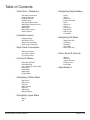
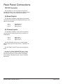
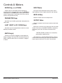
McCauley MCS 2.6 User’s Manual
V7.1 21-6-00 PRW
This equipment has been tested and found to comply with the following
Standards for Electromagnetic Compatibility and Electrical Safety:
• Radiated Emissions (EU):
• RF Immunity (EU):
• Mains Disturbance (EU):
• Electrical Safety (EU):
• Radiated Emissions (USA):
• Electrical Safety (USA):
• Electrical Safety (CAN):
EN55013
(1990) Associated Equipment
EN50082/1 (1992) RF Immunity, Fast Transients ESD
EN61000/3/2 (1995)
EN60065
(1993)
FCC part 15 Class B
UL813/ETL (1996) Commercial Audio Equipment
UL813/ETLc (1996) Commercial Audio Equipment
IMPORTANT SAFETY INFORMATION:
• DO NOT REMOVE COVERS.
• NO USER SERVICEABLE PARTS INSIDE, REFER SERVICING TO QUALIFIED SERVICE PERSONNEL.
• THIS EQUIPMENT MUST BE GROUNDED.
• IT SHOULD NOT BE NECESSARY TO REMOVE ANY PROTECTIVE
GROUND OR SIGNAL CABLE SHIELD CONNECTIONS TO PREVENT
GROUND LOOPS.
• ANY SUCH DISCONNECTIONS ARE OUTSIDE THE RECOMMENDED
PRACTICE OF McCAULEY SOUND, INC. AND WILL RENDER ANY EMC OR
SAFETY CERTIFICATION VOID.
For continued compliance with international EMC legislation ensure that all
input and output cables are wired with the cable screen connected to Pin 1 of the
XLR connectors. The input XLR Pin 1 is connected to the chassis via a low value
capacitor, providing high immunity from ground loops whilst ensuring good EMC
performance.
McCauley MCS 2.6 User’s Manual
page 2 of 15
Table of Contents
• Quick Start - Reference
• AC Power Connections
• Audio Connections
• Program Settings
• System Setup
• Configuring the MCS2.6
• Setting the Crossover Points
• Band Delays
• Adding EQ
• Setting the Limiters
• Other Features
• Installation Issues
• Voltage Settings
• AC Power Fusing
• Mechanical Installation
• Main Power Connection
• Rear Panel Connections
• RS-232 Connector
• (6) Outputs Section
• (2) Inputs Section
• Controls & Meters
• Enter Key (STORE)
• Parameter Keys
• Last / Next & Up / Down Keys
• Mute Key(s)
• Input Meter
• Mute Led(s)
• Output Meter
• Navigating: Outputs Menu
• Name
• Source
• Band Gain
• Limiter Threshold
• Delay
• Delay Link
• Polarity
• Low X-Over
• High Shape
• High X-Over
• Lock Mode
• Navigating: EQ Menu
• Adding New EQ
• EQ Shape
• Frequency
• Cut / Boost
• Width (Bell Only)
• Store, Recall & Security
• Storing
• Recalling
• System Security
• Program Lock
• Lock Mode
• Specifications
• Navigating: Utilities Menu
• Stereo Link
• Delay Units
• Lock Out
• MIDI Channel
• Contrast
• MIDI Dump
• Delete Program
• Navigating: Inputs Menu
• Delay
• EQ
McCauley MCS 2.6 User’s Manual
page 3 of 15
Quick Start Reference
Thank you for purchasing the McCauley MCS2.6 digital
systems controller. This section outlines a few basic procedures to get advanced users up and running quickly.
For complete information on all features and performance
issues, please familiarize yourself with the entire McCauley MCS2.6 user’s manual.
AC Power connection
The McCAULEY MCS2.6 has a universal voltage AC
Power input. Connect the McCAULEY MCS2.6 to AC
Power with the lead supplied. The unit will switch on automatically (there is no separate on/off switch). The display
will show the default screen, with the name and program
number of the current program. (This will be either the last
program recalled before the unit was switched off, or, in
the case of a unit with no stored programs, the default:
1 UNUSED)
Audio connections
Connect the inputs and outputs as desired. All inputs
and outputs are electronically balanced, with Pin 2 hot
signal (+ve). Do not put any audio through the unit at this
time.
Program settings
If your McCAULEY MCS2.6 has been already configured with a program, you only need to use the RECALL
mode to set the parameters to that program:
Press RECALL. Use the Parameter UP/DOWN
keys to select the designated program and press
RECALL again. Programs marked with the letter ‘
M’ are Master ‘OEM’ programs and have been
designed to match specific sound systems. Some
units will be locked to a specific program. In this
case most controls will be disabled and the unit
will be ready for use.
Setting up a system
To configure your McCAULEY MCS2.6, the mode of
the unit should be decided upon before setting up. Once
the Config is set (In the Utilities menu), the crossover
points, individual band delays, EQs, and limiter thresholds
can be set up. To enter the Utilities menu, press the
RIGHT key from the default screen.
McCauley MCS 2.6 User’s Manual
Configuring the McCAULEY MCS2.6
The McCAULEY MCS2.6 can be configured in one
of three modes: 2-way 3-channel, 3-way 2-channel or
Mono 5-way (MONO). To select the mode you wish to
use, enter the Utilities menu, and press the RIGHT key
until you reach the Config screen. Use the UP / DOWN
(PARAMETER) keys to select the option you wish to use.
NOTE: When the configuration is changed, the
unit will prompt for confirmation of the action. If the
ENTER (STORE) key is pressed, then the mode will
change, and DEFAULT VALUES WILL BE RESTORED.
It is advis- able to do a ‘Store’ before changing modes
if you have set up a program.
Setting the Crossover Points
Select the band to be edited by pushing the Access
UP/DOWN keys to cycle through inputs and outputs. Once
the band has been selected, press the LAST / NEXT
keys until the first crossover screen, displaying the lowshape filter slope, appears. Select the type of filter shape
by using the UP / DOWN (PARAMETER) keys to cycle
through the selection. Pushing the RIGHT key from here
will move to the Filter Frequency (Low slope) screen.
Use the UP / DOWN (PARAMETER) keys to select the
frequency. The high slope screen can be accessed after
this screen by pushing the RIGHT key.
Band Delays
Use the LAST / NEXT keys until the delay screen
appears. The delay is adjusted by the UP / DOWN
(PARAMETER) keys. Default settings for display and
adjustment of delay is in meters (m), but can be changed
to milliseconds (ms) or feet/inches (ft) in the Delay Units
screen in the Utilities menu. Bands can also be linked so
multiple outputs can be delayed as one using the Delay
Link utility.
Adding EQ
Use the LAST / NEXT keys to move to the EQ screen.
The EQ shape can be edited first. The shape of the EQ
can be selected from one of the following by pushing the
UP / DOWN (PARAMETER) keys:
• Hi-Shelf with 12dB slope (Hi12)
• Hi-Shelf with 6dB slope (Hi6)
• BELL
• Low-Shelf with 6dB slope (Lo6)
• Low-Shelf with 12dB slope (Lo12).
page 4 of 15
Quick Start Reference (cont.)
Pushing the RIGHT key from the EQ shape screen will
access the following facilities, in this order:
• Filter Frequency
• Cut/Boost
• Filter Bandwidth (BELL only)
Setting the limiters
Use the LAST / NEXT keys until the Limit screen appears.
Pushing the UP / DOWN (PARAMETER) keys will then
change the threshold. The output meters are calibrated to
this threshold setting.
Other Features
• Crossover slopes of 6, 12, 18, 24 or 48dB per
octave, filter types Butterworth or Linkwitz-Riley,
as appropriate.
• Output limiters on each band (mid-filter).
• High resolution input and output delays up to
630 seconds in 22 microsecond steps.
• Input LED metering, showing signals from -20dB
to clip level.
• Output LED metering, showing signals from
-20dB to +6dB over limit threshold.
• Front panel mutes.
• Polarity reverse on each output.
• Electronically balanced inputs and outputs.
• MIDI and RS-232 ports on rear panel.
McCauley MCS 2.6 User’s Manual
page 5 of 15
Installation Issues
Voltage Setting
The McCAULEY MCS2.6 uses a switched-mode power
supply which offers high efficiency and low heat generation. This power supply accepts universal AC Power input
voltages in the range 100V AC to 240V AC (nominal), and
requires no setting adjustment for AC power voltages in
this range. Minimum AC input voltage is 90 Volts, and the
maximum is 264 volts. Outside these ranges the unit will
not work satisfactorily, if at all. Voltages in excess of the
maximum will probably cause damage. Voltages below the
minimum will cause complete system shutdown. The flash
memory in the unit will preserve all data in the event of
a power failure.
AC Power Fusing
The Green-and-Yellow wire of the mains cord must
always be connected to an installation Safety Ground.
The Ground is essential for personal safety as well as
the correct operation of the system, and is internally connected to all exposed metal surfaces. Any rack framework
into which this unit may be mounted is assumed to be
connected to the same grounding circuit.
The incoming mains power is fused within the McCAULEY MCS2.6 by the fuse holder mounted on the rear
panel. Always replace with an identical 20mm x 5mm ‘T’
fuse, rated at 1A for continued protection from equipment
damage and fire. It is most important for continued safety
that this specification is strictly adhered to.
Main Power Connection
NOTE: There is no On/Off switch for the unit.
IMPORTANT: The wires in the main lead are color
coded in accordance with the following code.
• The wire which is colored Green and Yellow or
Green must be connected to the terminal which is
marked with the letter ‘E’ or by the Ground signal
or which is colored Green and Yellow or Green.
• The wire which is colored Blue must be con
nected to the terminal labelled ‘N’ or colored
Black or Blue.
• The wire which is colored Brown must be con
nected to the terminal labelled ‘L’ or colored Red
or Brown.
WARNING!
THIS APPLIANCE MUST BE GROUNDED.
Mechanical Installation
A vertical rack space of 1U (13⁄4” / 44.5 mm high) is
required. Ventilation gaps are unnecessary.
If the McCAULEY MCS2.6 is likely to undergo extreme
vibration through extensive road trucking and touring, it is
advisable to support the unit at the rear and/or sides to
lessen the stress on the front mounting flange. The necessary support can generally be bought ready-built as a rack
tray. As with any low-level signal processing electronics,
it is best to avoid mounting the unit next to a strong
source of magnetic radiation, for example, a high power
amplifier, to help keep residual noise levels in the system
to a minimum.
McCauley MCS 2.6 User’s Manual
page 6 of 15
Rear Panel Connections
RS-232 Connector
For connection to a PC for access to one or more
McCAULEY MCS2.6’s on a MIDI loop, the RS232 connection provides an easy way to upload new software.
(6) Band Outputs
The McCAULEY MCS2.6 audio outputs are electronically balanced and floating. Transformer balancing is available as a retrofit option.
• Pin 1
• Pin 2
• Pin 3
Shield/Ground
Signal Hot (+)
Signal Cold (-)
(2) Channel Inputs
The McCAULEY MCS2.6 audio inputs are electronically balanced. Transformer balancing is available as a
retrofit option.
• Pin 1
• Pin 2
• Pin 3
Open circuit
Signal Hot (+)
Signal Cold (-)
Use the UP/DOWN access keys to move between
Default, Utility, Input and Output menus (Horizontal columns).
Use the RIGHT and LEFT keys to move along each
menu.
Use the UP / DOWN (PARAMETER) keys to adjust
a parameter. (When adjusting a value, pressing a key
once will usually give a small increment / decrement
whilst holding a key down will give a larger increment/
decrement).
McCauley MCS 2.6 User’s Manual
page 7 of 15
Controls & Meters
ENTER Key (aka STORE)
Program data can be stored to one of 60 internal
memory locations using the Store facility. The ENTER key
also doubles as an STORE key for confirmation of some
actions. Program data is recalled to the unit from internal
memory using the Recall facility.
PARAMETER Keys
Controller keys for editing parameters displayed on the
LCD screen.
LAST / NEXT & UP / DOWN Keys
Controller keys for moving between screens to access
different parameters to edit.
MUTE Key(s)
Pressing a mute key will toggle the associated band
output on and off. The mute LED is illuminated when the
output is MUTED. Mute status is saved when a program
is stored.
McCauley MCS 2.6 User’s Manual
INPUT Meter
Input signal level referenced to the clip level. Actual
signal clipping will occur slightly above the ‘clip’ indicator.
MUTE LED(s)
Shows the mute status of the output band.
OUTPUT Meter
Shows the output of each channel relative to the limiter
threshold.
Moving to a new menu may not bring up the first screen
shown in each row, as McCAULEY MCS2.6 remembers,
and moves you to, the last screen accessed in each
menu.
• ENTER (STORE) and Recall are accessed by
pressing their respective keys.
After powering up, the McCAULEY MCS2.6 performs
internal checks and sets up the audio path before releasing the output mute relays. This takes a few seconds.
page 8 of 15
Navigating: Utilities Menu
Utilities Menu
Pushing the RIGHT key while viewing the default
screen will move you into the Utilities menu. The RIGHT
and LEFT keys are used to move along the Utilities path,
and the UP / DOWN (PARAMETER) keys are used to
change the selected parameter.
Stereo Link
This mode selects whether parameters will be adjusted
together or independently on each channel.
• The stereo link pairs in 2-channel 3-way are 1
& 2, 3 & 4 and 5 & 6.
• The stereo link pairs in 3-channel 2-way are 1
& 3, and 4 & 6.
Pushing the UP / DOWN (PARAMETER) keys selects
Stereo Link: ON or OFF.
Delay units
This selects the units used for displaying and adjusting
delays. ‘ms’ represents milliseconds, ‘ft’ represents feet (and
feet and inches for short delays), and ‘m’ represents metres.
Lock out
The Lock Out mode prevents access to editing functions on the input and output channels. Since this utility
is not password-protected, Lock Out can still be accessed
and turned off. This mode is intended only as a precaution
against accidental adjustments, and not as a tamper-proof
security lock.
MIDI channel
Here, you can select the MIDI channel that the unit is
assigned to (Channels 1 through 16 are available).
Contrast
This allows you to change the contrast of the LCD display.
MIDI dump
This utility allows you to dump the current program settings to another McCAULEY MCS2.6, or a MIDI storage
device for backup, or for the purpose of synchronising a
pair of units for stereo operation. Performing a MIDI dump
McCauley MCS 2.6 User’s Manual
will completely overwrite all programs in the receiving
device (Rx), including the current program, with those
from the sending device (Tx). If you are using the MIDI
Dump to transfer data to another McCAULEY MCS2.6
via MIDI ensure that both devices are set to the same
MIDI channel, and connect either the MIDI OUT of the Tx
device to the MIDI IN of the Rx device. Alternatively, the
units can be linked via their RS232 ports.
Each unit must be set to the correct MIDI mode, from
a choice of Multi, Master or PCPort on the MIDI mode
screen in the Utilities menu. The MIDI mode setting for
each device will depend on the protocol used and whether
synchronization between the units is required.
Protocol
RS232
RS232
RS232
RS232
RS232
RS232
MIDI
MIDI
Tx
PCPort
PCPort
Multi
Multi
Master
Master
Multi
Master
Rx
Multi
PCPort
Multi
PCPort
Multi
PCPort
Master
Master
Status
Synced
Synced
Synced
(NOTE: Units connected via MIDI port will only be
synchronized after a MIDI dump has been performed.
Units connected via RS232 do not require a MIDI dump in
order to synchronize, but if a MIDI dump is not performed,
each unit will contain different stored programs and current program settings until changes are made to each
setting individually on the Tx unit).
The default position for the MIDI dump screen is MIDI
DUMP: NO. Use the UP / DOWN (PARAMETER) keys to
select YES on the Tx unit, then press ENTER (STORE)
at the prompt, to confirm the dump. A percentage complete figure on the Tx screen will show how much data
has been transferred. The Rx screen will read ‘Warning!
Incoming Dump’. When the dump is complete, the Tx
screen will default to NO. The Rx screen will display the
name of the new current program.
(NOTE: All parameter edits in all stored programs
will be overwritten in any McCAULEY MCS2.6’s set to
the same MIDI channel. Use MIDI Dump with care!)
Delete Program
This facility allows any stored program to be removed
from the unit. Use the UP / DOWN (PARAMETER)
keys to select the desired program, and press ENTER
(STORE) to confirm deletion. (NOTE: Programs marked
‘M’ cannot be deleted from USER units)
page 9 of 15
Navigating: Inputs Menu
INPUTS MENU
There are two inputs available for routing to outputs
plus an internal mono sum of inputs A and B, referred to
as A+B. This gives the Input Channels:
• A, B, and A+B.
The facilities described in this section are common to
all inputs, except EQ, which is not possible on the mono
sum A+B signal.
• The first screen in the input menu is the DELAY
SCREEN. Pressing the RIGHT key will access the
EQ screens.
Delay
The delay on each input channel can be adjusted
individually, in 22 microsecond steps by pushing the UP
/ DOWN (PARAMETER) keys. (Holding a UP / DOWN
(PARAMETER) key down will increment/decrement the
amount of delay in larger steps). This delay is typically used
to set the delay for delay towers etc., or to stagger the
delays between the left and right channels to ‘move’ sound
lobes in an installation.
Delays can be viewed and adjusted in metres (default),
feet/inches, or milliseconds.
NOTE: The maximum delay value is restricted by
any delay on an output that is fed by the current input.
Input delay and output delay for any signal path is
limited to 630ms.
To select any of the output bands, press the UP/DOWN
keys until the output is shown on the screen.
EQ
To add EQ to an input, step through the functions on
the desired channel using the LAST / NEXT keys until you
reach the screen that shows the EQ parameter you wish
to edit. (See ‘EQ screens’ for more details).
McCauley MCS 2.6 User’s Manual
page 10 of 15
Navigating: Outputs Menu
OUTPUTS MENU
Name
The first screen in the Output menu is the Name function. Here you can identify each output with a name suitable to its function, selecting from a list of names in the
McCAULEY MCS2.6, such as SUB, or 2” HORN. Use the
UP / DOWN (PARAMETER) keys to select the desired
name. If the name selected while stereo is NOT linked
begins with L<space> or R<space>, then the L or R will
not be displayed when stereo linking is on.
Source
To change the source input, use the UP / DOWN (PARAMETER) keys until the desired input source is selected.
Band gain
Adjusts the output gain from -25dB to +4dB using the
UP / DOWN (PARAMETER) keys.
Limiter threshold
The band limiter threshold can be adjusted between
-20 to +10dBu in 0.2 dBu steps by pushing the UP /
DOWN (PARAMETER) keys to set the desired value to
match the sensitivity of the amplifier in use. McCauley
Sound recommends setting the limiter thresholds below
the amplifier clipping sensitivity by about 2dB. This prevents any transient overshoot driving the amplifier into clip
and so damaging your loudspeakers. Threshold setting
also determines the output meter sensitivity.
Delay
The output delays are most often used to electronically
align the driver voice coils with the other drivers in the
system, so the sound sources are coherent to the listener.
Each increment is only 22 microseconds, which translates in physical terms to a distance of 6.8mm
Delay link
The Delay Link option allows you to control several
band delays with a single adjustment. This means that
once all the drivers in a single cabinet have been aligned,
the whole cabinet can be delayed relative to the input
signal, or another cabinet, by linking these band delays
McCauley MCS 2.6 User’s Manual
as one. Any offsets applied before linking will be
retained after linking. In the Delay Link screen, Use the
UP / DOWN (PARAMETER) keys until the desired linking
configuration is shown.
• In mono configuration, 1 will link to 2, 2 will link
to 3 etc.
• In 2-channel 3-way configuration, 1 will link to 3,
3 will link to 5, 2 will link to 4 and 4 will link to 6.
• In 3-channel 2-way configuration, 1 will link to 4,
2 will link to 5 and 3 will link to 6.
Polarity
The polarity invert function allows the phase of an
output to be rotated by 180 degrees. Default is uninverted.
Pushing the Parameter UP key will invert the polarity of
the output. Pushing the Parameter DOWN key will return
the polarity of the output to uninverted.
This screen is used to select the filter type/shape for
the lower band edge (high-pass) of the current output
band. The band edge will be highlighted on the graphic
on the screen.
The available filter types are as follows, in this order:
• Butterworth 12dB /Octave
• Linkwitz-Riley 12dB Octave
• Butterworth 18dB / Octave
• Butterworth 24dB / Octave
• Linkwitz-Riley 24dB / Octave
• Butterworth 48dB / Octave
• Linkwitz-Riley 48dB / Octave
Pushing the UP / DOWN (PARAMETER) keys will
scroll through the above list.
Low Xover
The lower edge (high-pass) of the crossover band can
be set over a wide frequency range from OUT (no roll
off) through 15Hz to 16kHz. Pushing the Parameter UP
key will increase the frequency, with OUT as the final
step. Pushing the Parameter DOWN key will increase
the frequency, to the final clockwise position OFF, which
mutes the output.
High Shape
Selects the Edge filter type and slope as for the higher
page 11 of 15
Navigating: Outputs Menu (cont.)
(low-pass) band edge.
High X-Over
This function works in a similar way to the Low Xover,
except that OUT is the last step at the clockwise position.
NOTE: Pushing the UP / DOWN (PARAMETER) keys
will decrease the frequency, to the final clockwise
position OUT, which DOES NOT mute the output.EQ
McCauley MCS 2.6 User’s Manual
page 12 of 15
Navigating: EQ Menu
To add EQ to an input, step through the functions on
the desired channel using the LAST / NEXT keys until
you reach the screen that shows the EQ parameter you
wish to edit.
If the McCAULEY MCS2.6 is configured for MONO, all
EQs will be mono. If configured for 2x2+1 (“stereo”), EQs
will be marked as Stereo ‘S’ when STEREO LINK is ON,
and the stereo marker will show an ‘S’ next to the EQ
number. Available spare EQ filters are also shown.
Adding a New EQ:
If you press the RIGHT key and the screen does not
change, then you have reached the last EQ currently in
use. To add an EQ, the cut/boost of the highest EQ must
be edited. Another EQ (assuming there are spare EQs)
will then be inserted automatically.
NOTE: The A+B signal is summed after the EQ sections on A and B, so the A+B signal is affected by
A and B EQ.
EQ Shape
The shape of the EQ can be selected from one of the
following by pushing the UP / DOWN (PARAMETER) keys:
• Hi shelving with 6dB slope (Hi6)
• Hi shelving with 12dB slope (Hi12)
• BELL
• Low shelving with 6dB slope (Lo6)
• Low shelving with 12dB slope (Lo12).
Frequency
Pushing the UP / DOWN (PARAMETER) keys adjusts the EQ
frequency. The filter position is shown graphically by the cursor,
and the Frequency of EQs can range between 15Hz and 16kHz.
Cut/Boost
Pushing the Parameter UP key to add boost (+ gain)
or DOWN for cut (- gain). Cut/boost is available between
+15dB and -15dB, in 0.2dB increments.
Width (BELL only)
Pushing the Parameter UP key widens the EQ (lower
Q), pushing the DOWN key makes the EQ narrower
(higher Q). EQ Width is available between 0.05 and 3
Octaves, in 0.05 increments.
McCauley MCS 2.6 User’s Manual
page 13 of 15
Store, Recall & Security Functions
Storing and Recalling a program can be done at any time
using the ENTER (STORE) and RECALL keys on the left
hand side of the LCD. The McCAULEY MCS2.6 can hold 60
programs internally. To reset a unit to default values, use the
configuration parameter in the Utilities screen.
NOTE: If the unit is prompting for confirmation of
an action at any time, the ENTER (STORE) key is used
to conform the action, and pressing it at this point will
not access the STORE facility.
Storing
Pressing the ENTER (STORE) key will access the
Store screen.
Use the LAST / NEXT keys (or push the UP / DOWN
(PARAMETER) keys) to move along the program name.
While the Program number is highlighted, pushing the UP /
DOWN (PARAMETER) keys will cycle through programs 1-60.
Whilst each of the letters in the Program name are
highlighted, pushing the UP / DOWN (PARAMETER) keys
will cycle through all available characters.
The last space in the program name is reserved for Program lock. Pushing the UP / DOWN (PARAMETER) keys will
turn this on/off. If a program has this flag set to on (so the
program name displays a key at the right hand side), a new
program, or edited version of the current program, cannot
later be stored in this location. This lock can be turned off at
any time in order to delete or overwrite the program. If you
try to store a program in place of a locked program, the unit
will display “PROGRAM LOCKED! “, but will then highlight the
key icon, which gives you the option of turning off the lock if
you wish to overwrite the existing program.
NOTE: The edit flag ‘*’ appears when there are
unsaved changes to a program, compared to the initial
status of the last recalled/stored program. When a program is stored to internal memory, the edit flag will disappear. Once the program name has been entered, and
the Program lock status cleared, pressing the ENTER
(STORE) key again will prompt the message “STORE
UNLOCKED? ”, asking whether the program should be
stored with a Program lock on/off. Use the UP / DOWN
(PARAMETER) keys to turn the Lock on/off, the default
setting being ON. Once the Lock status is set, push
the ENTER (STORE) key a final time to commit the
program to memory. The display will now default back
to the screen displayed before the STORE facility was
accessed. To exit from the store screen without storing a
program, press the recall button.
McCauley MCS 2.6 User’s Manual
Recalling
Pressing the RECALL key will access the recall screen.
This facility is displayed in the same way as the store
facility.
The Parameter UP / DOWN keys are used to select
the program number to recall (when highlighted). When
the program you wish to recall has been selected, push
the RECALL key again to recall the program. The unit will
display a message showing that data is being recalled,
and will then display the default screen once the recall
is complete.
To exit from the recall screen without recalling a program, press the ENTER (STORE) button.
System Security
Any changes made to an audio system have the potential to be damaging, even if only accidentally made. For
this reason several different security systems are built in
to the McCAULEY MCS2.6 to protect the speakers. Each
of the security levels locks different groups of variables
away from accidental or malicious adjustment.
Program lock
This is a flag that is available for each stored program.
A program can be locked when it is stored - the user
is prompted when ENTER (STORE) is pressed for the
second time. Locking a program in this way is purely to
protect the user against accidentally overwriting a stored
file. The lock status can be changed by anyone unless
the program is OEM locked (see next page). A program
locked in this way is indicated by a key symbol.
Lock mode
The Lock Mode in the Utility Menu can be turned on
at any time.
When Lock Mode is set to ON, the user can move
around the screens but no variables can be changed
except for the LCD screen contrast and, of course, the
Lock Mode.
Locking the unit in this way is only to protect the user
against other users changing the system setup accidentally or against unauthorized people intentionally changing
the system. This status can be changed by anyone who
knows how to operate the McCAULEY MCS2.6.
page 14 of 15
Specifications
• Dynamic Range
• Noise Floor
• Frequency Response
• Distortion (THD)
Typically 108dB, unweighted 22Hz to 22kHz
• Inputs
• Input Impedance
• Maximum Input Level
Electronically balanced & floating
• Outputs
• Maximum Output Level
• Channel Separation
• Power Supply
• Power Consumption
Electronically balanced & floating
-98dBu (default gain set -10dB)
<±0.25dB, 15Hz-20kHz with filters out
<0.007%, 20Hz-20kHz @+10dBu input level
10kW
+20dBu, balanced
+10dBu into 600W
>80dB, 20Hz-20kHz
AC Mains 50/60Hz, 90V - 264V
<30VA
McCauley Sound, Inc.
16607 Meridian Avenue East
Puyallup, WA 98375 - USA
Call Toll Free 1-877-McCauley
253.848.0363
253.841.3050 fax
http://www.mccauley.com
McCauley MCS 2.6 User’s Manual
page 15 of 15