1
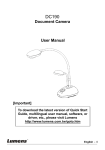
GV-3D People Counter User’s Manual Beta Version This document is a beta version of a software product that may be changed substantially prior to final commercial release. This document is provided for informational purposes only and GeoVision Inc. makes no warranties, either express or implied, in this document. Information in this document is subject to change without notice. © 2012 GeoVision, Inc. All rights reserved. Under the copyright laws, this manual may not be copied, in whole or in part, without the written consent of GeoVision. Every effort has been made to ensure that the information in this manual is accurate. GeoVision, Inc. makes no expressed or implied warranty of any kind and assumes no responsibility for errors or omissions. No liability is assumed for incidental or consequential damages arising from the use of the information or products contained herein. Features and specifications are subject to change without notice. GeoVision, Inc. 9F, No. 246, Sec. 1, Neihu Rd., Neihu District, Taipei, Taiwan Tel: +886-2-8797-8377 Fax: +886-2-8797-8335 http://www.geovision.com.tw Trademarks used in this manual: GeoVision, the GeoVision logo and GV series products are trademarks of GeoVision, Inc. Windows and Windows XP are registered trademarks of Microsoft Corporation. December 2012 ii Contents Contents ............................................................................................................................ iii Chapter 1 Introduction ..................................................................................................... 1 1.1 Features ................................................................................................................. 2 1.2 Packing List ............................................................................................................. 2 1.3 Options.................................................................................................................... 3 1.4 Overview ................................................................................................................. 4 1.4.1 Front View ................................................................................................ 4 1.4.2 Rear View................................................................................................. 5 1.5 The IR Remote Control............................................................................................ 6 Chapter 2 Getting Started................................................................................................. 8 2.1 Connecting the Device ............................................................................................ 8 2.2 Installing Wall Mount (Optional) ............................................................................... 9 2.3 Installing VESA Monitor Mount (Optional) ...............................................................10 Chapter 3 The OSD Menu ................................................................................................11 3.1 Setting the Network ................................................................................................12 3.2 Setting the GV-3D People Counter .........................................................................13 3.3 Adjusting Device Time ............................................................................................14 Chapter 4 The Web Interface...........................................................................................15 4.1 Accessing the GV-Web Report Lite ........................................................................15 4.2 Setting the GV-3D People Counter .........................................................................16 4.3 4.2.1 Detection Setting .....................................................................................16 4.2.2 SMTP Setting ..........................................................................................20 4.2.3 Auto Export Setting..................................................................................21 4.2.4 Database Setting .....................................................................................21 Accessing People Counting Data............................................................................22 4.3.1 Device .....................................................................................................22 4.3.2 Group ......................................................................................................24 4.3.3 Log ..........................................................................................................26 4.3.4 Query ......................................................................................................27 Chapter 5 Content Designer............................................................................................30 5.1 Minimum System Requirements .............................................................................30 5.2 Installing the Content Designer...............................................................................31 5.3 Creating a Screen Layout .......................................................................................32 5.3 Exporting the Screen Layout to GV-3D People Counter..........................................34 Chapter 6 GV-IP Device Utility.........................................................................................35 iii 6.1 Setting the GV-3D People Counter .........................................................................36 Specifications .....................................................................................................................38 Appendix ............................................................................................................................39 Optimal Installation..........................................................................................................39 Detection Limitations.......................................................................................................40 WARRANTY POLICY ..........................................................................................................43 iv 1 Chapter 1 Introduction Introduction The GV-3D People Counter integrates Asus Xtion Pro (Live) to count and analyze the number of people passing by the designated detection area. You can connect the GV-3D People Counter with a VGA or HDMI monitor for direct display of counting data and configuring device settings through on-screen display (OSD) menu. GV-3D People Counter comes with a built-in Web interface, the GV-Web Report Lite, for easy setup and looking up people counting data. Display Monitor A I / VG HDM GV-3D People Counter Asus Xtion Pro (Live) Live people counts USB Inter net Infrared sensor to detect people GV-Web Report Lite or GV-Web Report Counting data and charts Figure 1-1 1 1.1 Features • Counts the number of people (In and Out) • Support for HDMI and VGA compatible monitors • IR remote control to configure on-screen display (OSD) menu • GV-Web Report Lite: Web interface to look up people counting data and charts • Support for data compiling and chart analysis on GV-Web Report • Audio alarm for traffic in wrong direction and exceeding maximum entries, exits or stays • Content Designer to customize layout on display monitor • SD card 1.2 Packing List 1. GV-3D People Counter × 1 2. IR remote control × 1 3. AC / DC adapter × 1 (12 V / 3 A, 36 W) 4. Power cord x 1 5. Software DVD x 1 2 1 1.3 Introduction Options Optional devices can be purchased separately for GV-3D People Counter. Contact your dealer for more information. Options Wall Mount Kit Detail The Wall Mount Kit is used to mount the GV-3D People Counter to the wall. VESA Monitor-Mount Kit z L-type brackets x 2 z Small screws x 4 The VESA Monitor Mount Kit is used to mount the GV-3D People Counter to the back of a VESA monitor. Asus Xtion Pro Live z VESA monitor mount bracket x 1 z L-type brackets x 2 z Large screws x 4 z Small screws x 8 The Xtion Pro Live is a motion sensor used to detect the number of people who have walked through the detection area. Asus Xtion Pro (Live) In-Ceiling Mount The In-Ceiling Mount is used to mount Asus Xtion Pro (Live) on the ceiling. 3 1.4 Overview This section identifies the components of the GV-3D People Counter. 1.4.1 Front View Figure 1-2 No. Name Function The green LED indicates the Asus Xtion Pro (Live) is connected. 1 LED Indicators 2 USB 3 IR 4 Default Reset the GV-3D People Counter to the default factory settings. 5 SD Card Slot Connect to a SD card for local storage and firmware upgrade. The red LED indicates the power is supplied. Connect to an Asus Xtion Pro (Live). Built-in IR receiver to receive the IR signals from the IR remote control. Restoring GV-3D People Counter to Default Settings To restore GV-3D People Counter to default settings, press and hold the Default button on the front panel. Release the Default button when the green LED stops blinking. The GV-3D People Counter will automatically reboot after loading default. Note: The power should always be on during the process of loading default. 4 1 1.4.2 Introduction Rear View Figure 1-3 No. Name Function 1 Ethernet Connect to an Ethernet. 2 SPDIF Reserved (not enabled). 3 HDMI Connect to an HDMI supported display device. 4 VGA Connect to a VGA monitor. 5 L/R Connect to a speaker. 6 Power OFF/ON Switch the power on or off. 7 DC 12V Connect to power by using the supplied power adapter. 5 1.5 The IR Remote Control 1 2 5 3 6 7 4 Figure 1-4 No 1 Name Number / Alphabets / Punctuation Marks Function Enter the numbers, alphabets or punctuation marks. 2 Back Exits the Setup Menu and return to the counting page. 3 Direction Arrows Move up, down, right and left in the Setup Menu. 4 Rec Saves the settings in the Setup Menu. 5 Menu Switch to the setup menu. 6 OK Enter the setup options in the Setup Menu. 6 1 Introduction Press Shift and 0~7 to switch to one of the 8 resolutions below. 7 Shift Shift + 0 : VGA_640 x 480 Shift + 4 : HDMI_480p Shift + 1 : VGA_1024 x 768 Shift + 5 : HDMI_720p Shift + 2 : VGA_1280 x 768 Shift + 6 : HDMI_1080i Shift + 3 : VGA_1366 x 768 Shift + 7 : HDMI_1080p Note the resolution switch will cause the GV-3D People Counter to automatically reboot. 7 Chapter 2 2.1 Getting Started Connecting the Device Figure 2-1 1. Connect a display device to VGA video connector or HDMI connector for video and audio alarm combined outputs. 2. Connect to a standard network cable. 3. If you use a VGA monitor, connect a speaker to L/R port for audio alarm. 4. Connect the Asus Xtion Pro (Live) to the USB port of the GV-3D People Counter. The recommended installation height for Asus Xtion Pro (Live) is between 1.8 – 5 meters. 5. Connect to power using the supplied power adapter. 6. Switch the Power button to ON. Note: 1. You can only connect GV-3D People Counter to one display device through HDMI or VGA connector. The video signal will be unstable if multiple display devices are connected. 2. For more accurate counting results, avoid placing the Asus Xtion Pro (Live) where it can be subjected to direct sunlight or exposed to IR LED. 3. GV-3D People Counter is only compatible with Asus Xtion Pro (Live) firmware V5.3.26 or later. 8 2 Getting Started 2.2 Installing Wall Mount (Optional) You can separately purchase the Wall Mount Kit to mount GV-3D People Counter on a wall. 1. Unscrew the 4 screws on the back panel of the GV-3D People Counter. Figure 2-2 2. Use the 4 screws in the package to tighten the L-type brackets on the GV-3D People Counter. L-Type Bracket L-Type Bracket Figure 2-3 9 2.3 Installing VESA Monitor Mount (Optional) You can separately purchase the VESA Monitor Mount for installing GV-3D People Counter to the back of a VESA monitor. 1. Follow steps 1 and 2 in 2.2 Installing Wall Mount to tighten the L-type brackets on the back panel of GV-3D People Counter. 2. Using the 4 large screws, tighten the VESA monitor mount bracket on the back of the computer monitor. Figure 2-4 3. Use the 4 small screws to tighten the GV-3D People Counter and the VESA monitor mount bracket together. Figure 2-5 10 3 Chapter 3 The OSD Menu The OSD Menu After connecting the GV-3D People Counter to the necessary devices, turn the power switch on the GV-3D People Counter to ON and the window below appears. Figure 3-1 To configure video output, network and time settings, press Menu on the remote control to enter the OSD (On-Screen Display) menu. There are three tabs in the setup menu: Network, Info and Time Setup. 11 3.1 Setting the Network Under the Network tab, you can configure the IP address of the GV-3D People Counter. If installed in a LAN with the DHCP server, the GV-3D People Counter will use a dynamic IP address by default. If installed in a LAN without the DHCP server, the default IP address 192.169.0.100 will be applied. Figure 3-2 1. To assign a static IP address for the GV-3D People Counter, select Static IP and enter a fixed IP address, subnet mask, DNS and gateway. 2. To use a dynamic IP assigned by the DHCP Server, select DHCP. Once connected, the current IP address will be displayed next to Connected IP. 3. Press [REC] to save the settings. The GV-3D People Counter will reboot to apply the settings. Note: You can also use the GV-IP Device Utility to set the IP address of the GV-3D People Counter. See Chapter 6 GV-IP Device Utility for details. 12 3 3.2 The OSD Menu Setting the GV-3D People Counter Under the Info tab, you can set up the login ID, password, device name, video output type and resolution. You can also update the firmware of the GV-3D People Counter. Figure 3-3 User Login ID / Password: Set the ID and password to access the GV-3D People Counter. Device Name: Change the display name of the GV-3D People Counter if necessary. Output: Select VGA or HDMI according to the video output of the display monitor. Resolution: Select a screen resolution from the following options: HDMI at 60 Hz 480p 720p 1080i 1080p VGA at 60 Hz 640 x 480 1024 x 768 1280 x 768 1366 x 768 Firmware Update: Select Yes and press OK to begin updating firmware. Before pressing OK, copy the firmware file to the root folder of the SD card and insert the SD card to the GV-3D People Counter. Make sure there is only one firmware file in the SD card. The device will restart after the firmware upgrade is complete. 13 Note: 1. By default, the video output is set to VGA with 1024 x 768 resolutions. 2. You need to allocate at least 50 MB in the device storage before upgrading the firmware. 3. You can also use the GV-IP Device Utility to rename the GV-3D People Counter and update the firmware. See Chapter 6 GV-IP Device Utility for details. 3.3 Adjusting Device Time To adjust the time of the GV-3D People Counter, select the Time Setup tab and select Adjustment. Enter the correct time and press [REC] to save. Figure 3-4 Note: If the GV-3D People Counter has been set to synchronize time with another server on the Detection Setting page of GV-Web Report Lite, you will not be able to adjust the device time on the OSD menu. For settings Time Sync, see 4.2.1 Detection Setting. 14 4 The Web Interface Chapter 4 The Web Interface After installing the GV-3D People Counter on the network, you can access GV-Web Report Lite to set up the Asus Xtion Pro (live) and look up counting data. 4.1 Accessing the GV-Web Report Lite System Requirements To access GV-3D People Counter through Web browser, ensure your PC is in good network connection, and use one of the following web browsers: z Mozilla Firefox V16.0.2 or later z Google Chrome V.22.0.1.1229.94 or later Logging In 1. In your Web browser, type the IP address or the domain name of the camera in the Location / Address field. Figure 4-1 2. Type the ID and password. The default ID and password are admin. 3. Type the characters shown in the image and click Login. 15 4.2 Setting the GV-3D People Counter Once you have logged in to the GV-Web Report Lite, click the Setup tab on the top. There are four setting pages available: Detection Setting, SMTP Setting, Auto Export Setting and Database Setting. 4.2.1 Detection Setting Under the Detection Setting page, you can set the In / Out direction, specify detection area, set up DDNS service, and report the collected data to other GV-Web Report Lite / GV-Web Report. Figure 4-2 16 4 The Web Interface [Live View] Draw a line on the live view to mark the boundary of the detection zone. Subjects moving across the blue line toward the red arrow will be counted as Out. Subjects moving across the blue line toward the green arrow will be counted as In. To change the direction of the arrows, you can click the Change button after Direction Change to the right of the live view. Live View: Click to see the live image of the detection area captured by the infrared sensor of the Asus Xtion Pro (Live). The live image is in black and white. REC: Records the live view for 30 seconds. Only one video can be stored in the SD card at a time. The existing recording will be overwritten by the new recording. Download Recorded File: You can download the recorded file and provide the recording to service personnel for troubleshooting. [User Settings] Machine Name: Change the display name of the GV-3D People Counter if necessary. Login Name / Password: Change the login name or password for accessing the GV-3D People Counter if necessary. The default login name and password are admin. Port: Modify the port or keep the default 30003. When connecting to other servers, GV-3D People Counter must use the same port as the servers. [DDNS Settings] DDNS (Dynamic Domain Name System) provides a convenient way of accessing GV-3D People Counter with a dynamic IP address. DDNS assigns a domain name to the GV-3D People Counter, so that the Administrator does not need to check if the IP address assigned by DHCP Server or ISP (in xDSL connection) has changed. 1. Click Register to register a GeoVision DDNS Server or apply for a Host Name from other DDNS service provider’s website. 2. Type the Host Name used to link to the GV-3D People Counter. 3. Type the Name and Password used to enable the service from the DDNS. 4. Click Connect. [Schedule Settings] To enable people counting only during certain time of the day, click the checkbox and specify a time period. 17 [People Counter Settings] For more precise counting results, specify the height of the Asus Xtion Pro (Live) and the minimum people height. 1. Type the height of the installed Asus Xtion Pro (Live) in the Xtion Device Height field. Depending on how high the Asus Xtion Pro (Live) is installed, the detectable height range for people will vary. 2. In the Minimum People Height field, type the minimum people height you want to detect. 3. Click the Detail button to see an illustration of the detectable height range and the dimension of the detection area based on the height you specified. Figure 4-3 Wrong Direction Alarm: Enable if the detection area is exit only or entrance only, and an audio alarm will sound when GV-3D People Counter detects people going in the wrong direction. Direction Change: To reverse the direction of the In and Out arrows in the Live View screen, click the Change button. 18 4 The Web Interface [Report to Other Servers] You can send People Counting data to up to three other GV-Web Report Lite server and / or GV-Web Report. 1. Select Report to Server. 2. Type the IP address of the GV-Web Report Lite or GV-Web Report. 3. Modify the default Port 30003 of necessary. 4. Type the Name and the Password to access the GV-Web Report Lite or GV-Web Report. 5. If you click Time Sync under one of the servers, the time of the current GV-3D People Counter will be synchronized with the selected server. To cancel time synchronization, double-click the selected radio button. Note: GV-3D People Counter is only compatible with GV-Web Report V2.2.3.0 or later. [Load Default] Click Load Default to reset the Detection Setting page back to default values. 19 4.2.2 SMTP Setting You can receive a daily report of the counting results by e-mail. First, set up your mail server on this page and then refer to 4.2.3 Auto export Setting to enable the function. Figure 4-4 SMTP Server: Type your SMTP Server’s URL address or IP address. Port: The default port for most SMTP servers is 25. However webmail Yahoo and Hotmail generally use differently SMTP port. In this case, check your e-mail provider for the SMTP port number. Sender Email: Type the sender’s e-mail address. Login Required: If your mail server needs login authentication, select the checkbox and type your login username name and password. Use SSL: Select this option, if the SMTP server needs a secure connection. 20 4 The Web Interface 4.2.3 Auto Export Setting To automatically receive a report of the counting data everyday, select Enable Auto Export and type the Recipient E-mail. Use the Auto Export Time drop-down list to select what time to receive the report and click Apply. Figure 4-5 Make sure you have already set up the mail server under the SMTP Setting page. Refer to 4.2.2 SMTP Setting for details. 4.2.4 Database Setting You can see the size of the inserted SD card, size of space used by current database and size of free space. To clear the content of the SD card, click Reset Database. Figure 4-6 21 4.3 Accessing People Counting Data After setting up the GV-3D People Counter to start collecting data, you can access the people counts, tables and charts. Use one of the following tabs in GV-Web Report Lite to look up the data. • Device: Displays the counted data and graphs from all connected GV-3D People Counters. The data is updated every minute. • Group: You can group the connected GV-3D People Counters and see the data of the set group. • Log: Allows you to look up the data of a specified time period from the selected GV-3D People Counter. • Query: Provides the daily, weekly, monthly and yearly people counting graphs and tables. 4.3.1 Device The data on the main page of the Device page is updated every minute from the GV-3D People Counter. The page displays the people counts and graphs of all connected GV-3D People Counters. Figure 4-7 22 4 The Web Interface The tables on the main page show the following information for each GV-3D People Counter. In: The number of people entered on that day since 0:00 or since the start of schedule. Out: The number of people exited during the day. Stay: The number of people remaining. That is subtracting the number of Out from the number of In. Wrong Direction: If you have enabled the Wrong Direction Alarm in the Setup page, the number of people moving in the wrong direction during the day will be shown. The Total In, Total Out, Stay and Wrong Direction below the tables are the total number of people counted from all connected GV-3D People Counters. On the left menu, these options are available: Total List: Select one device under the list to access its individual counts. A green mark indicates that the device is now connected to GV-Web Report Lite; otherwise a red mark appears. Counting Signage: Access the number of people counted on the day and the recent records of entries and exits. When people move in the wrong direction, the alarm will sound. When people moving toward In direction are detected, the new data entry will be highlighted in green. Out entries will be highlighted in red. Figure 4-8 23 4.3.2 Group On the Group page, you can group the connected GV-3D People Counter, and see the people counts of the set group. You can also set up the maximum number of people entered, left and remaining to activate the computer alarm. E-mail notification can be activated when the number of people remaining reaches the pre-defined maximum. To set up a group: 1. Select Add Group from the left menu. This page appears. Figure 4-9 2. Name the group. 3. Select the GV-3D People Counters you want to include in the group. 4. In the Maximum In field, set the maximum number of people that can enter during the day before activating the computer alarm. 5. In the Maximum Out field, set the maximum number of people that can leave during the day before activating the computer alarm. 6. In the Maximum Stay field, set the maximum number of people that can remain during the day before activating the computer alarm, sending a notification e-mail or triggering an output device. 7. Click Submit. 8. From Total List in the left menu, select the set Group to see the sum of every people count from those selected GV-3D People Counter. 24 4 The Web Interface To organize multiple groups into subgroups, click Setting Group Relations in the left menu. Drag and drop a group under another group to make it a subgroup. Figure 4-10 On the left menu of the Group page, you can find these options: Total List: Access the people counts of the set groups updated every minute. Counting Signage: Access the people counts of the set groups updated in real time. When the limit of Maximum In, Maximum Out or Maximum Stay is reached, the warning texts will be displayed on the page and the computer alarm will be activated too. 25 4.3.3 Log On the Log page, you can look up the people counts per hour of a specified time period from the selected GV-3D People Counter or group. Figure 4-11 To search the log data: 1. Select a specific GV-3D People Counter from the Device drop-down list or a created group from the Group drop-down list. 2. Specify Start Time and End Time of the log data. 3. You can select whether to search the DST (Daylight Saving Time) data. Select All indicates searching all data including DST data, Y indicates searching only DST data and N indicates not searching DST data. 4. Click Query to display the search results. To back up the search results in EXCEL or WORD, click the icons at the bottom of the Query Result List. Under Wrong Direction, you can click [Detail] to see the time of the wrong entry or exit during that hour. Figure 4-12 26 4 The Web Interface 4.3.4 Query The Query page provides you with the daily, weekly, monthly and yearly people counting graphs and tables. To search the counting data, select a GV-3D People Counter from the Device drop-down list or a created group from the Group drop-down list, specify a date, and select the options below. Use the Chart drop-down list graph, line graph or pie graph. to choose to display the data using bar Note: Pie graph is not available for the following types of data: • In/Out Counts per hour and Total Stay • Total In, Out and Stay per Hour • In Counts per Hour • Out Counts per Hour • Total Stay per Hour [Daily Report] Display the counting report of the specified date. In/Out Counts per hour and Total Stay: The hourly number of people entered and left, and the total number of people remaining until now. Difference between In and Out per hour: The hourly number of people remaining. Total In, Out and Stay per hour: The total number of people entered, left and remaining during the day. 27 The following figure is an example of the In/Out Counts per hour and Total Stay option. The value 12, 15 indicates the count of remaining people until 12 pm is 15. Figure 4-13 [Weekly Report] Display the weekly report that contains the data of 7 days before your specified date. In Counts per hour: The hourly number of people entered for the week. Out Counts per hour: The hourly number of people left for the week. Total Stay per hour: The hourly number of people remaining for the week. In Percentage per day: The daily percentage of people entered for the week. In Percentage per hour: The hourly percentage of people entered for the week. Stay Percentage per hour: The hourly percentage of people remaining for the week. 28 4 The Web Interface The following figure is an example of the In Percentage per day option. The value 2012-12-20 (Thu), 29 (26.85%) indicates the total number of entered people on 2012/12/20 is 29. The number takes up 26.85 percent of the total people entered for the week. Figure 4-14 [Monthly Report] In Percentage per day: The daily percentage of people entered in the month. In Percentage per hour: The hourly percentage of people entered in the month. Stay Percentage per hour: The hourly percentage of people remaining in the month. [Yearly Report] In Percentage per month: The monthly percentage of people entered in the year. Out Percentage per hour: The hourly percentage of people entered in the year. Stay Percentage per hour: The hourly percentage of people remaining in the year. 29 Chapter 5 Content Designer Using the Content Designer, you can customize the screen layout for display monitor to show the in counts, out counts, stay counts and the current time. 5.1 Minimum System Requirements The minimum system requirements to install and run the Content Designer: 32-bit Windows XP / 7 64-bit Windows XP / 7 OS Supported CPU Pentium 4, 3.0 GHz RAM 1 GB HDD 80 GB VGA AGP or PCI-Express, 800 x 600 (1280 x 1024 recommended), 32-bit color DirectX 9.0c .NET Framework 3.5 4 The Web Interface 5.2 Installing the Content Designer Follow the steps below to install the Content Designer: 1. Insert the Software DVD to your computer. It runs automatically and a window pops up. Figure 5-1 2. Select Install DirectX 9.0c and follow the on-screen instructions. 3. Select Install Microsoft .NET Framework 3.5) and follow the on-screen instructions. 4. Select GeoVision Content Designer (Beta Version) and follow the on-screen instructions. 31 5.3 Creating a Screen Layout 1. To create a project, click File on the menu bar and select New Scenario. 2. Select GV-3D People Counter and a screen resolution. The screen resolution must match the resolution you set for the display monitor. Figure 5-2 Note: The following resolutions for HDMI and VGA video outputs are available: HDMI at 60 Hz 480p 720p 1080i 1080p VGA at 60 Hz 640 x 480 1024 x 768 1280 x 768 1366 x 768 For HDMI 480p, select 720 x 480; for HDMI 720p, select 1280 x 720; for HDMI 1080p and 1080i, select 1920 x 1080. 3. On the top-left corner, click the Background Image icon and click Browse to select a picture in PNG, JPEG or BMP format to be the background image. Figure 5-3 32 4 The Web Interface Note: The In Count, Out Count, Stay Count and Current Time will be shown on the display monitor as numbers only. If you wish to label the counting data, you will need to add a background picture with text added where the data will be shown. For example: Figure 5-4 4. On the left side, click the In Count, Out Count, Stay Count and Current Time icons to add these objects to the main screen. Figure 5-5 5. You can adjust the size and position of the objects using the Size and Position fields in the bottom-left corner or drag and drop the object boxes. To resize the box for Current Time, double-click the object and select from a list of pre-defined resolutions. 33 5.3 Exporting the Screen Layout to GV-3D People Counter 1. To preview the created screen layout, click Preview screen. on the main 2. To save the screen layout, click File and select Output Scenario. 3. Click to browse the location to save the screen layout. The screen layout will be saved in a folder named 3DPeopleCounter. Figure 5-6 4. In a SD card, create a folder named Scenario and copy the 3DPeopleCounter folder to the Scenario folder. 5. Turn off the GV-3D People Counter, insert the SD card, and restart the GV-3D People Counter to apply the new screen layout. 34 4 The Web Interface Chapter 6 GV-IP Device Utility GV-IP Device Utility can detect GV-3D People Counter in the LAN and allows you to quickly set the IP address of the device, upgrade firmware and reboot the device. To Install GV-IP Device Utility 1. Insert the Software DVD to your computer. It runs automatically, and this window appears. Figure 6-2 2. Select Install GV-IP Device Utility, and follow the on-screen instructions. 35 6.1 Setting the GV-3D People Counter 1. To start the GV-IP Device Utility, go to Windows Start, point to Programs and select GV IP Device Utility. The window below appears and automatically searches for any GV-IP device under LAN. Figure 6-2 2. Double-click a GV-3D People Counter. This dialog box appears. Figure 6-3 36 4 The Web Interface 3. Click the different tabs to access the following settings: Set IP Address: Type the IP address, subnet mask, default gateway and DNS server of the GV-3D People Counter. Firmware Upgrade: To upgrade the firmware, click Browse to specify the path of the firmware file and click Upgrade to proceed. You can select Upgrade all devices to upgrade all other GV-3D People Counter of the same username and password. Device Name: Renames the GV-3D People Counter. Reboot: Reboots the GV-3D People Counter. 37 Specifications HDMI 480p, 720p, 1080i, 1080p VGA 640 x 480, 1024 x 768, 1280 x 768, 1366 x 768 Video Output IR Remote Control Connectors Yes Power 12V DC Jack Ethernet 10/100 Ethernet, RJ-45 Connector Video Output HDMI, VGA Local Storage SD card slot (for Class 6 or above, FAT32 format) Audio 3.5 mm Jack (for wrong direction alarm) Operating Temperature 0°C ~ 40°C / 32 °F ~ 104 °F Operating Humidity 20 % ~ 80 % (with no condensation) Power Source DC 12 V / 3A Maximum Power Consumption 36 W Dimensions (W x H x D) 182.5 × 29 × 141.5 mm / 7.19 × 1.14 × 5.58 in Weight 615 g / 1.36 lb Regulatory CE, FCC compliant On-Screen Display English GV-Web Report Lite English, Traditional Chinese, Simplified Chinese Language 38 Appendix Appendix Optimal Installation To increase the accuracy of people counting results, be sure to install the Asus Xtion Pro (Live) with the correct lighting conditions and avoid placing IR LED nearby. The recommended installation height for Asus Xtion Pro (Live) is between 1.8 – 5 meters. Avoid Direct Sunlight Direct sunlight on the detection area may show up as a white region on the live view and interferes with people counting results. Avoid IR LED IR LED from the left of the view interferes with the IR sensor of the Asus Xtion Pro (Live) and causes part of the person’s head to appear dark. 39 Detection Limitations There are situations that may cause GV-3D People Counter to falsely detect the number of people. Below are examples of situations that may or may not result in false detection. Actual: 1 Counted: 1 Actual: 1 Counted: 1 Actual: 1 Counted: 1 Actual: 2 Counted: 2 Actual: 2 Counted: 1 40 Standing upright Leaning forward Squatting down Shoulder to shoulder Head leaning on shoulder Appendix Actual: 2 Counted: 1 Actual: 2 Counted: 2 Actual: 4 Counted: 4 Head to head One hand on shoulder Multiple people Carrying a large backpack: Actual: 1 Backpack in close contact with the Counted: 1 person’s head. Actual: 2 Backpack at a distance from the Counted: 3 person’s head. 41 Pushing a cart: Actual: 1 Counted: 1 Cart close to the person’s body. Cart away from the person’s body. Actual: 1 Tip: Set a minimum detection height Counted: 2 that is higher than the cart to avoid false detection. Pushing a wheelchair: Actual: 2 The person pushing the wheelchair is Counted: 2 standing upright. Actual: 2 Counted: 1 42 The person pushing the wheelchair leans over and overlaps with the wheelchair user. Warranty Policy WARRANTY POLICY GeoVision, Inc. (“GeoVision”) hereby provides two types of Limited Warranty for iDi Signage products as below: ■ ONE (1) YEAR - LIMITED WARRANTY Including: 1. Slim – Bezel Signage Displays SQP series and; 2. Static Light box System including A3 CCFL and A2 CCFL. ■ TWO (2) YEARS - LIMITED WARRANTY Including: Signage Player PN300 and PA200 series. All aforementioned products, EXCLUDE OTHER PACKAGED ACCESSORIES AND ALL SOFTWARE, (hereinafter called “Products”) will be free from defects in materials/workmanship during the terms of these Limited Warranties (“Limited Warranties”) from the date of purchase. These Limited Warranties parts and labor warranty are applicable to Products purchased via authorized distribution and sales channels. If a defect arises and a valid claim is received by GeoVision within Limited Warranties Period, at its option, GeoVision will (1) repair Products at no charge, using new or refurbished replacement parts, or (2) exchange Products with a Product that is new or which has been manufactured from new or serviceable used parts and is at least functionally equivalent to the original Products. GeoVision warrants replacement parts or repairs for thirty (30) days from the date of GeoVision shipment or for the remainder of Limited Warranties Period, whichever provides longer coverage for you. When a Product or part is exchanged, any replacement item becomes your property and the replaced item becomes GeoVision’s property. It is customer’s sole responsibility and requirement to prove these Products are under warranty (by submit your sales invoice and bar code), otherwise GeoVision will determine these Products’ warranties period at its option. GeoVision reserves the right, at its sole discretion and any time, to modify and adjust the scope and content of Products and its 43 warranty without prior notice, however, any modification and adjustment thereafter will not affect or interrupt any rights belonging to Products you purchased already. LIMITATIONS OF WARRANTIES Limited Warranties apply only to Products manufactured by or for GeoVision that can be identified by the "iDi Signage" or "GeoVision" trademark, trade name, or logo affixed to them. Limited Warranties do not apply to any non-iDi Signage and non-GeoVision products including counterfeited products. GeoVision and iDi Signage are not liable for any damage to or loss of any profit, programs, data, or other information stored on any media, or any non-iDi Signage and non-GeoVision Products or part not covered by these warranties. Recovery and reinstallation of system and application software and user data are not covered under Limited Warranties. Limited Warranties do not apply if: a) Products have been subjected to abnormal use, improper storage, unauthorized modifications, unauthorized repair, misuse, neglect, abuse, accident, alternation, removal of any stickers or labels on the hardware, improper hardware/software installations, or other acts that are not the faults of GeoVision, including damage caused by shipping; b) Products have been damaged from exposure under circumstances which is over weatherproof specification of the product, an Act of God, or improper use of any electrical source, or the connection to other products not recommended for interconnection by iDi Signage or GeoVision; c) Products have defects or damage caused due to computer virus attack, internet or technical issues; d) Products serial number have been removed, defaced or altered; or e) Products have been sold by an unauthorized distributor or retailer. g) Products have been interoperated with any non-GeoVision and non-iDi Signage products which GeoVision and iDi Signage does not approve the compatibility. DISCLAIMER OF WARRANTIES EXCEPT AS SPECIFIED IN THESE WARRANTIES, ALL EXPRESS OR IMPLIED CONDITIONS, REPRESENTATIONS, AND WARRANTIES INCLUDING, WITHOUT LIMITATION, ANY IMPLIED WARRANTIES OR CONDITION OF MERCHANTABILITY, FITNESS FOR A PARTICULAR PURPOSE, NON-INFRINGEMENT, SATISFACTORY QUALITY, NON-INTERFERENCE, ACCURACY OF INFORMATIONAL CONTENT, OR ARISING FROM A COURSE OF DEALING, LAW, OR TRADE PRACTICE, ARE HEREBY EXCLUDED TO THE EXTENT ALLOWED BY APPLICABLE LAW AND ARE EXPRESSLY DISCLAIMED BY GEOVISION AND IDI SIGNAGE. TO THE EXTENT IMPLIED 44 Warranty Policy WARRANTIES CANNOT BE EXCLUDED, SUCH WARRANTIES ARE LIMITED IN DURATION TO THE EXPRESS WARRANTIES PERIOD. BECAUSE SOME STATES OR JURISDICTIONS DO NOT ALLOW LIMITATIONS ON HOW LONG IMPLIED WARRANTIES LASTS, THE ABOVE LIMITATION MAY NOT APPLY. THESE WARRANTIES GIVE CUSTOMERS SPECIFIC LEGAL RIGHTS, AND CUSTOMER MAY ALSO HAVE OTHER RIGHTS WHICH VARY FROM JURISDICTION TO JURISDICTION. THIS DISCLAIMER AND EXCLUSION SHALL APPLY EVEN IF THE EXPRESS WARRANTIES SET FORTH ABOVE FAILS OF ITS ESSENTIAL PURPOSE. GEOVISION AND IDI SIGNAGE MAKE NO WARRANTIES AND LIABILITIES, EXPRESS OR IMPLIED, WITH RESPECT TO NON-GEOVISION AND NON-IDI SIGNAGE PRODUCTS OR THEIR INTEROPERATION WITH THE PRODUCTS AND DISCLAIM ANY IMPLIED WARRANTIES OF MERCHANTABILITY, COMPATIBILITY, FITNESS FOR A PARTICULAR USE, OR INTEROPERATION BETWEEN PRODUCTS AND NON-GEOVISION/ NON-IDI SIGNAGE PRODUCTS. GEOVISION AND IDI SIGNAGE SHALL NOT BE LIABLE FOR INCLUDING BUT NOT LIMITED TO ANY DATA LOST, LOSS AND DAMAGE, DIRECT OR INDIRECT, FOR ANY INTEROPERATION BETWEEN THE PRODUCTS AND NON-GEOVISION/ NON-IDI SIGNAGE PRODUCTS. LIMITATION OF LIABILITY Regardless whether any remedy set forth herein fails of its essential purpose or otherwise, in no event will GeoVision, iDi Signage or its suppliers be liable for any lost revenue, profit or lost or damaged data, business interruption, loss of capital, or for special, indirect, consequential, incidental, or punitive damages however caused and regardless of the theory of liability or whether arising out of the use or inability to use the GeoVision and iDi Signage Products or otherwise and even if GeoVision or iDi Signage has been advised of the possibility of such damages. In no event shall GeoVision and iDi Signage liabilities to customer, whether in contract, tort (including negligence), breach of warranty, or otherwise, exceed the price paid by customer for the Software that gave rise to the claim or if the Software is part of another Products, the price paid for such other Products. Because some states or jurisdictions do not allow limitation or exclusion of consequential or incidental damages, the above limitation may not apply to you. In no event shall GeoVision’s and iDi Signage’s total liabilities to you for all damages (other than as may be required by applicable law in cases involving personal injury) exceed the amount of two hundred dollars (U.S. $200.00). The foregoing limitations will apply even if the above stated remedy fails of its essential purpose. Customer agrees that the limitations of liability and disclaimers set forth herein will apply regardless of whether customer has accepted any other Products or service delivered by GeoVision. Customer acknowledges and agrees that GeoVision has set its prices in reliance 45 upon the disclaimers of warranties and the limitations of liability set forth herein, that the same reflect an allocation of risk between the parties, and that the same form an essential basis of the bargain between the parties. These Warranties shall be governed by and construed in accordance with the laws of Taiwan, Republic of China and United State, without reference to or application of choice of law rules or principles. The United Nations Convention on the International Sale of Goods shall not apply. If any portion hereof is found to be void or unenforceable, the remaining provisions shall remain in full force and effect. FOR AUSTRALIA ONLY: Our products come with guarantees that cannot be excluded under the Australian Consumer Law. You are entitled to a replacement or refund for a major failure and for compensation for any other reasonably foreseeable loss or damage. You are also entitled to have the products repaired or replaced if the products fail to be of acceptable quality and the failure does not amount to a major failure. Please visit www.accc.gov.au for more information. GeoVision Inc. 9F, No.246, Sec.1, Neihu Rd., Neihu District Taipei 114, Taiwan R.O.C. Tel: 886-2-8797-8376 Email: [email protected] GeoVision Inc. Warranty Policy last updated on October 24, 2012. 46