1
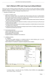
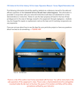
USER MANUAL
NEPTUNE
22
Important Safety Information
Laser Safety
Your laser machine is a Class I product as rated by CDRH. In every Class I laser device,
the laser beam is enclosed in a cabinet and the equipment has safety interlock mechanisms
to protect the operator from injury.
The machine is equipped with a red-dot laser pointer that allows you to position the cutting
laser beam. This is a Class IIIa laser device that requires extra safety precautions; i.e.,
avoid placing your eyes in the path of the red beam.
Safety Instructions
l
l
l
l
l
Before operation, carefully read the warning labels on your machine unit as well as
the cautions and warnings in this manual.
Connect the machine to a properly grounded power outlet. Make sure the voltage
level of the machine matches that of the power source.
Don't open the back door of the unit while system power is on since the power supply
inside contains high voltage.
Don't attempt to modify or disassemble the laser module.
Invisible intensive laser radiation may cause physical burns or severe eye damage. Be
sure to wear appropriate safety goggles during operation, especially when engraving
mirrors or coated metals such as enameled brass and anodized aluminum.
NOTE: Each LaserPro laser machine is equipped with a safety goggle, if you need
another one, please contact LaserPro for it or try to get one that meets the following
specification.
190-398 nm OD5+
10,600 nm OD5+
Visible light transmission: 92.9%
l
l
l
l
l
l
l
l
Good ventilation is required to remove odors and vaporized materials from the work
area of the machine. An exhaust system is recommended.
Do not work with reflective metals, heat sensitive surfaces, or other materials that
may produce toxic substances such as PVC and Teflon.
A fire extinguisher should always be available near the machine.
When cutting materials that easily catch fire, such as acrylic, wood, or paper, you
should turn on the air compressor to blow out any flames that may occur.
Never leave the machine unattended during operation, especially when engraving the
above-mentioned materia ls.
If the worktable is used for cutting purposes, do not leave any material underneath, as
when material at top is cut through, the material below will burn easily due to trapped
heat.
Follow the instructions on maintaining and cleaning your system. Not only will this
enable you to engrave efficiently, but also it will ensure that your machine runs safely.
Every door has key to lock. Please make sure the door is locked in order to ensure the
safety.
2
33
Warning Labels
CAUTION
AVOID PLACING YOUR EYES IN
THE RED BEAM PATH
DANGER
INVISIBLE LASER RADIATION WHEN OPEN
AND INTERLOCK FAILE D OR DEFEATED
AVOID EYE OR SKIN EXPOSURE
DIRECT OR SCATTERED RADIATION
DANGER
INVISIBLE LASER RADIATION WHEN OPEN
AVOID EYE OR SKIN EXPOSURE
DIRECT OR SCATTERED RADIATION
3
44
WARNING!!
Do not use reflective metals, heat sensitive
surfaces or other materials that may produce
toxic substances, such as PVC and Teflon.
4
vv
Unpacking
Perform the following steps to unpack your machine.
CAUTION: The machine weighs about 400 kg (884 pounds). To prevent damage to the machine
or injury to personnel, please get assistance. Do not try to lift the equipment alone.
Step 1. Use an M12 open end or impact wrench to unscrew and remove the top.
Step 2. Remove the 4 sides of the crate in the order.
Step 3. Take the protective wrap off the machine. For step 1 and 2, please see Figure 1.
Step 1
Step 2
Figure 1
Step 4. Take out the wooden holding stick (see Figure 2).
Holding Stick
Figure 2
Step 5. Loosen the pink packing strips and remove them. Firstly push the lock on the strip
down (see Figure 3), and then pull it out to the top (see Figure 4) before you can loosen the
strips (see Figure 5).
v
vivi
Figure 3
Figure 4
Figure 5
Step 6. Unscrew the two settled boards (see Figure 6), take them out of the crate, and then
turn them up side down.
vi
vii
vii
Settled
Boards
Figure 6
Step 7. Put the settled boards at each end of the crate base to form a slope (see Figure 7).
Wooden
Block
Figure 7
Step 8. Screw them to the crate base (see Figure 8).
Figure 8
Step 9. Remove the wooden block from the crate base (see Figure 7), and then unscrew the
four holding stands so that they can be moved up (see Figure 9).
vii
viii
viii
Figure 9
Step 10. Finally roll the machine out of the crate base (see Figure 10).
Figure 10
Step 11. Remove the X-axis restraining strips (see Figure 11).
Figure 11
Step 12. Save the crate for shipping in case any return service is needed.
viii
ixix
Packing List
The following table lists all the items included in your laser machine package. If any of
them is missing or damaged, please contact your dealer immediately.
ITEM
QUANTITY
Cleaning Set
cotton swab
lens cleaner
lens tissue (lint free)
1 pack
1 bottle
1 pack
1
4” Manual Focus Gauge (red)
AC Power Cord
1
Printer Cable
1
LaserPro Neptune Driver
1
Mirror (for Mirror 2 or 3)
1
Goggles
1 pair (optional)
ix
xx
Quick Guide
Installation
1.
2.
Carefully read the Important Safety Information printed at the front of this manual.
Before starting adjusting the level of working table, please make sure Neptune is
located at plain place, and adjust the four stands by screw driver gradually. Please
adjust each stand a little each time and then adjust another one. Do not finish one
stand adjustment and process the other, it would make the working table out of shape.
Stand
3.
Use a high-precision level along each of the Y-axis’s to adjust the stands until the
bubble is centered in the level.
Figure 11
x
xixi
4.
Screw the three-hole air ventilation port onto the upper side of the left panel located
in the back of the machine (see Figure 12). Connect the air exhaust system. For more
information, please refer to “Connecting the Exhaust System” on page 10.
Figure 12
5.
Connect the air compressor to the airflow controller that is beneath the worktable (see
Figure 13).
Figure 13
xi
xii
xii
6.
Connect the water tubes of the water cooler at the bottom left of the machine (see
Figure 14).
Figure 14
7.
The inlet and outlet of the water cooler have to match the outlet and inlet of the
machine (see Figure 15).
Water
In
Water
Out
Figure 15
8.
9.
Unscrew the plastic plug from the water cooler inlet pipe, and pour distilled water
into the water cooler through the inlet pipe.
Fill the water cooler up with water until the red float marker surpasses the level
marker “Low”.
xii
xiii
xiii
10. Screw the needle shaped screws into the holes on the cutting table (see Figure 16).
Figure 16
11. Without performing step 9, turn the worktable over, and it becomes an engraving
table.
12. Connect the machine to a properly grounded power outlet. Make sure the voltage
level of the machine (marked on a label above the AC power connector) matches that
of the power source (see Figure 17).
13. Set up the host computer and connect it to the parallel or serial printer port that is
located at the outer right hand side of the machine (see Figure 17).
xiii
xiv
xiv
Figure 17
14. Turn on the computer.
15. Run the Windows Printer Setting program to install the LaserPro Neptune printer
driver (see Figure 18).
Figure 18
xiv
xv
xv
Operation
1.
2.
3.
Carefully read the Important Safety Information printed at the front of this manual.
Turn on the host computer.
Run your favorite graphics program (e.g., CorelDRAW, PhotoShop and PhotoPaint)
and open the file you will be using for engraving or cutting.
4. Turn on the machine. After system initialization, the lens carriage moves to the
machine’s zero-point position (upper left corner of the worktable ) and the machine is
ready to receive a file .
5. Adjusting the focus:
l
l
l
Press the
key on the control panel once and make sure the machine is
under “STOP” status.
Loosen the two screws holding the lens carriage in place, move it up and then tighten
the screws to lock it in position (see Figure 20).
Place the red or blue focus gauge metal on the surface of the material (see Figure 19).
Figure 19
NOTE: There are two kinds of focus gauge metal. The blue one is for the 2-inch lens focus gauge
and the red one is for the 4-inch lens focus gauge.
l
Loosen the lens carriage screws so as to allow the bottom of the lens carriage to settle
on top of the red focus gauge metal (see Figure 20).
Figure 20
xv
xvi
xvi
l
Tighten the lens carriage screws and remove the red focus gauge metal by placing two
fingers in the two holes and sliding it out from under the lens carriage (see Figure 21).
Figure 21
5.
6.
7.
8.
9.
Press
once to turn the machine back to “START” status.
Turn on the exhaust system.
Turn on the air compressor.
Turn the water cooler on.
From the host computer, print the file to the machine using the LaserPro Neptune
printer driver.
NOTE: 1. The maximum thickness of the work piece is 10cm. 2. It is important to note that
the water cooler must be on before operating the machine.
xvi
xvii
Contents
Important Safety Information.........................................................1
Laser Safety ........................................................................................................ 2
Safety Instructions ............................................................................................... 2
Warning Labels .................................................................................................... 3
Unpacking .......................................................................................v
Packing List ........................................................................................................ix
Quick Guide ....................................................................................x
Installation .......................................................................................................... x
Operation ...........................................................................................................xv
Contents ...................................................................................... xvii
Introduction ....................................................................................1
Front View .......................................................................................................... 2
Rear View ........................................................................................................... 3
Motion System .................................................................................................... 4
Focal Length and Lens ......................................................................................... 5
Lens Carriage ...................................................................................................... 5
Recommended Configuration ............................................................................... 6
Hardware Installation.....................................................................7
Side Panel........................................................................................................... 7
Power Cable Connection ...................................................................................... 8
Computer ............................................................................................................ 8
Air Compressor ................................................................................................... 9
Exhaust System ..................................................................................................10
Water Cooler ......................................................................................................11
Software Installation.....................................................................13
Installing the Neptune Driver...............................................................................13
Operation......................................................................................25
Environment.......................................................................................................25
Flexible Utility of Your Memory Buffer ...............................................................25
Control Panel......................................................................................................26
Hardware Operation ............................................................................................33
Software Operation .............................................................................................35
System Setup......................................................................................................36
Setting Neptune Driver Parameters ......................................................................48
Basic Maintenance ........................................................................57
Routine Cleaning ................................................................................................57
Mirrors and Lenses .............................................................................................57
Replacing the Laser Module ................................................................................62
Troubleshooting.............................................................................63
Quality Problems ................................................................................................63
Non-operational Problems ...................................................................................63
Specifications.................................................................................65
Optional Items ....................................................................................................66
Frequently Asked Questions..........................................................67
xvii
1
1
Introduction
Thank you for choosing LaserPro Neptune, an inexpensive but powerful laser machine that
is with oversized working area and ingenious versatility, and is easy to use and maintain.
Please read this manual carefully in order to take full advantage of what the machine has to
offer.
This chapter provides basic information on your laser machine.
Chapter 1 Introduction
2
Front View
The following figure shows the external features at the front and on the right-hand side of
your machine unit.
C
A
D
B
Figure 22
A. Control panel: see page 22 for more information.
B. Door 2: provides passage for the air compressor and access to the system’s circuit
board and power board.
C. Door 1: provides access to the laser module, water-cooling system and power supply.
D. Front cover: protects the operator from laser beam.
Chapter 1 Introduction
3
Rear View
The following figure shows the external features at the back and on the left-hand side of
your machine.
B
A
Figure 23
A. Door 3: provides access to mirror 1 for adjustment or cleaning.
B. Left panel: provides passage for the exhaust tube.
CAUTION: Do not open Door 1 and Door 3 when the machine's power is on. Please note that
there are security latches inside each door except for Door 2. Therefore once you
open any one of the doors during operation, the action will activate the security
latches that will shutdown the laser temporarily for safety’s concern until the doors
are closed again.
Chapter 1 Introduction
4
Motion System
The following figure illustrates the motion system of your machine.
I
A
J
H
C
E
B
D
Figure 24
A.
B.
C.
D.
E.
F.
G.
H.
I.
J.
Mirror 4 and holder
X-axis belt
Y-axis belt
Worktable
Lens carriage
Y-axis motor (not shown)
X-axis motor (not shown)
Exhaust gas pipe
Air blower tube
Capstan
Chapter 1 Introduction
5
Focal Length and Lens
Focus, or focal point, is the point where the laser beam, converging after traveling through
a lens, comes into contact with the material to be engraved or cut. By changing the lens,
i.e., changing the focal length, a focus can be made larger or smaller. For optimal
engraving results, the lens needs to be lined up just right with the material to be engraved.
The longer the focal length, the bigger the size of the beam spot will be. High-resolution
lenses are designed for precision engraving. Low-resolution lenses are used mostly for
cutting because of its less beam divergence that results in a straighter cut in thick materials.
However, using higher resolution takes longer for engraving. On the other hand, the large
spot size of low-resolution lenses can spread the laser’s heat over a larger area, which
helps minimize melting and thus can be applied to engraving of certain kinds of plastics.
You can use a manual focus gauge to ensure accurate focusing of the beam. The following
table lists the lenses and their matching focus gauges available.
Focal Length
Color
of Lens
Color of Focus
Resolution
Gauge
Cutting Capacity
2.0" (Optional)
Blue
Blue
High
Thin
4.0" (Standard)
Red
Red
Low
Thick
Lens Carriage
Driven by two servomotors, the lens carriage carries the laser beam to the right places
when engraving. This is also the part of the machine where you change the lens and insert
the manual focus gauge (see Figure 25).
Lens
Carriage
Figure 25
Chapter 1 Introduction
6
Recommended Configuration
To engrave or cut, you must use a computer that is connected to the printer port of the
machine, a graphics application program, and preferably a scanner. Here's the
recommended configuration:
Computer
Type
PC
CPU
Pentium or better
DRAM
32 MB or up
FDD
One 3.5" 1.44 MB
HDD
1.2 GB Hard Drive or up
SVGA
15" Super VGA monitor
Parallel
Port
SPP preferred (selected from BIOS Setup); if
you select ECP, the length of the cable should
not exceed 1.8 M.
Scanner
Type
Flat Bed
Resolution
200 dpi minimum
Software
Driver
GCC driver (designed under Windows 95 or
later version)
Operating System
Windows 95 or later
Graphics Program
CoreDRAW 9 or later, or any program that
outputs HPGL commands
Chapter 1 Introduction
7
2
Hardware Installation
This chapter provides information on installing the hardware, including the computer, the
air compressor, the exhaust system, and the water-cooling system.
CAUTION: Before making any hardware connections, make sure all power switches are in the
OFF position and all power cables are disconnected from the power outlet. Moreover,
check the plug to see if it matches the wall outlet. If not, please contact your dealer.
Side Panel
The computer and the power cable are connected to the machine's side panel. The
following figure shows the connectors and switches on the side panel (see Figure 26).
A
B
C
D
F
E
Figure 26
Chapter 2
Hardware Installation
8
A.
B.
C.
D.
E.
F.
Power ON/OFF switch
3 amp resettable fuse
15 amp resettable fuse
AC power connector
Parallel interface connector
Serial interface connector
Power Cable Connection
1.
2.
Insert the male power cable into a grounded power outlet.
Plug the other end (female) into the machine. The machine has been designed to
switch from 100 ~ 240 VAC automatically. However for the 100W machine,
only 220 ~ 240 VAC can be used.
Computer
Your machine communicates with the computer either through the parallel (Centronics) or
the serial (RS-232C) port.
Parallel Transmission
If you are using a PC with your machine, this is the recommended method for data
transmission, since it is faster than an RS-232 connection.
1.
2.
Attach one end of the parallel cable to the parallel port on the machine.
Attach the other end to the parallel port on the PC.
CAUTION:
Never use a mechanical switch box when a second printer port is required, because
the electrical surges can cause damage to the computer and the machine.
Serial Transmission
If you are using an IBM PC, PS/2, or a compatible computer, you can use the serial ports
for connection.
1.
2.
Attach the 25-pin male connector of the RS-232 cable to the serial port on the
machine.
Attach the other end of the RS-232 cable to the serial port of the host computer.
Macintosh
To operate the machine with a Macintosh computer (e.g., Power Mac), you need a MAC
modem cable (DIN-8 to DB-25) as an adapter to connect to the RS-232 cable.
1.
2.
3.
Attach the 8-pin connector of the Mac modem cable to the Macintosh computer.
Attach the 25-pin female connector of the RS-232 cable to the Mac modem cable.
Attach the other end of the RS-232 cable to the serial port on the machine.
Chapter 2
Hardware Installation
9
Air Compressor
When cutting materials that can easily catch fire, such as acrylic, wood or paper, an air
compressor is needed to deliver compressed air through the air nozzle to blow out any
flames that may occur. The air compressor is connected to the air hose connector (see
Figure 27) located beneath the worktable.
Adjusting
Screw
Ring Lock
Figure 27 Air Hose Connector
Connecting the Air Compressor
To connect the air compressor to your machine:
1.
2.
3.
Take the end of the air hose that comes from the air compressor.
Insert it into the inlet of the connector until it reaches the end. The orange ring lock
will secure the hose firmly.
Turn the airflow adjusting screw on the air hose connector counterclockwise to allow
air passage.
Disconnecting the Air Compressor
To disconnect the air compressor from the machine:
1.
2.
Turn the airflow valve on the compressor to the OFF position.
Pressing the ring lock upward (to the direction of airflow), pull the air hose from the
connector.
Chapter 2
Hardware Installation
10
Exhaust System
The exhaust system of the machine is designed to vent and filter odorous or toxic gasses
produced when you engrave materials such as rubber or acrylic.
Connecting the Exhaust System
You connect the ventilator/filter to the worktable of the machine using three exhaust tubes,
as described in the following steps:
1.
Connect the larger-gauge tube from the ventilator beneath the connection port, and
lock the clamping loop around the tube (see Figure 28).
Figure 28
2.
Connect the two smaller-gauge and the smallest-gauge tubes that enter the worktable
area to the top of the connection port, and lock clamping loops around the tubes (see
Figure 29).
Smaller
Gauge
Tube
Smaller
Gauge
Tube
Smallest
Gauge
Connection
Port
Figure 29
Disconnecting the Exhaust System
To disconnect the exhaust system:
Chapter 2
Hardware Installation
11
1.
Remove the three exhaust tubes from the air ventilation connection ports.
2.
Remove the smaller tubes from the machine through the rear cover.
Water Cooler
The water cooler that will be connected to the machine consists of a cooling system, and
two tubes that allow inflow and outflow of water. When you turn the power on, the cooling
system is activated and delivers cool water to the laser module to absorb heat produced
there, and then brings it back to the cooling system to cool down.
Adding Water
The water cooler is an outer device that has to be connected to the machine. For water
cooler setup that includes adding water, please refer to the water cooler manual.
NOTE: 1. If you need to ship the machine after using it, you must remove the tubes that are
connected beneath the machine, and then lift the two tubes up as high as possible so that
the cooling water will not drain out. 2. Do not disconnect the tubes too often, in case the
tubes become loose. 3. Do not spill any water onto the internal components of the machine
while removing it.
Chapter 2
Hardware Installation
13
3
Software Installation
The host computer recognizes your laser machine as a printing device. Before using the
machine, you must install the right printer driver for the machine on the computer. You can
use the driver diskette that came with your package to install the LaserPro Neptune driver.
Installing the Neptune Driver
Perform the following steps to install the Neptune driver:
1.
From the Windows desktop, click "Start" and select "Printer and Faxes” click the
"Printers" icon (see Figure 30).
Figure 30
Chapter 3 Software Installation
14
2.
Double-click the "Add Printer" icon when you see the following message (see Figure
31).
Figure 31
3.
Click "Next" when you see the following message (see Figure 32).
Chapter 3 Software Installation
15
Figure 32
Chapter 3 Software Installation
16
4.
When you see the following message, choose “Local printer” and then click “Next”
(see Figure 33).
Figure 33
5.
Click "Have Disk … " when you see the following message (see Figure 34).
Chapter 3 Software Installation
17
Figure 34
Chapter 3 Software Installation
18
6.
Click “Have Disk” to find the correct file (see Figure 35).
Figure 35
7.
Click "Browse" when you see the following message (see Figure 36).
Chapter 3 Software Installation
19
8.
Figure 36
Chapter 3 Software Installation
20
9.
When you see the following message, click the port you want to use with your
machine (in this example, Neptune), and then click “Next” (see Figure 37).
Figure 37
Chapter 3 Software Installation
21
10. Select “Replace existing driver” and click Next “Step”
Figure 38
11. Select “NO” when asked to print a test page and click NEXT STEP
Chapter 3 Software Installation
22
Figure 39
12. Click FINISH to complete the Add Printer Wizard
Chapter 3 Software Installation
23
Figure 40
In a few seconds, you will see the following message, showing Neptune's icon as an installed printer for
Windows (see Figure 41).
Figure 41
Now the LaserPro Neptune printer driver is installed completely. Do not forget to take the
GCC driver disk from the floppy drive and store it in a safe place.
Chapter 3 Software Installation
25
4
Operation
This chapter teaches you how to operate your laser machine. It gives detailed information
on the ideal working environment and flexible utility of the memory buffer for the
machine, and the control panel, which you use to monitor and control Neptune's hardware.
It also provides information on how to set the parameters before you print a graphic file
from the host computer.
Environment
l
l
l
l
A clean, well-ventilated room with a temperature of 15℃~25℃ (60℉~78℉)
(especially the temperature of 25℃), and a relative humidity between 30﹪and 40﹪
as an office type of environment.
Avoid from unstable voltage supply.
Short path for an effective air exhaust.
Have a fire extinguisher available at all times.
Flexible Utility of Your Memory Buffer
The standard memory buffer size of Neptune is 16Mb and can be expanded to 64Mb
(32Mb SIMM × 2).
You can choose “Multiple file” mode with limited memory to save files and recall them for
constant applications. Or, you can choose “Single file” mode to get an unlimited data
output. However, if the file size is less than the memory buffer size of the machine
installed, the file sent under “Single file” mode will be saved, and it’s output can be
repeated.
Chapter 4 Operation
26
Choice of Multiple File Mode or Single File Mode (see Figure 42)
Power ON
LaserPro Neptune
Firmware V x. xx
Copyright 200x
Initializing
Please wait
Press FUNCTION key.
Set memory buffer?
Yes: ENTER
End operation: Esc
Delete all files?
Press ENTER key.
Single /1 File
Ok: ENTER
Change: △ or ▽
Multiple /100 Files **
Ok: ENTER
Change: △ or ▽
Single /No Repeat
Ok: ENTER
Change: △ or ▽
Figure 42
NOTE: 1. ** means default or current setting. 2. All function keys should be operated under STOP
condition. 3. The NEXT FILE key is invalid under “Single file” mode.
Control Panel
The control panel consists of one LCD display, three LED status indicators, and fourteen
keys, as shown in Figure 43.
Chapter 4 Operation
27
Figure 43
LCD Display
The LCD display allows you to monitor the LaserPro Neptune system while cutting or
engraving. It also provides an interface for you to carry out system setup and diagnostics.
LED Indicators
DOOR OPEN
This LED indicator lights when the front door is open. It goes off when the front door is
closed.
POWER
This LED indicator lights when the machine is powered on. It goes off when the machine’s
power is off, or the power board or main circuit board is damaged.
LASER
This LED indicator lights when the machine is firing laser beams. It goes off as soon as the
machine stops firing laser beams.
Keys
UP ARROW
Pressing this key selects the previous option in a menu (see Figure 44).
Figure 44
DOWN ARROW
Pressing this key selects the next option in a menu (see Figure 45).
Chapter 4 Operation
28
Figure 45
RIGHT ARROW
Pressing this key takes you to the next menu (see Figure 46).
Figure 46
LEFT ARROW (ESC)
Pressing this key allows you to exit and to be back to the system setup program (see Figure
47).
Figure 47
SPEED
Pressing this key sets up speed for desired effect (see Figure 48). When working without
Neptune’s driver, press the FUNCTION key, and then select one of the sixteen setups and
set up desired cutting speed. No matter the Neptune’s driver is used or not, you can change
speed anytime by pressing PAUSE key prior to the action during cutting or engraving. To
set up desired speed, press ENTER and then press RESUME to continue the job.
Figure 48
NOTE: Do not change the speed while working on the piece. It is only changeable during testing
that is under the raster mode. However, this concern would not matter if it were operated
under the vector mode.
FUNCTION
Pressing this key runs the system setup program and brings up its main menu on the LCD
(see Figure 49).
Chapter 4 Operation
29
Figure 49
POWER
Pressing this key sets up laser power for desired depth and effect (see Figure 50). Other
conditions are the same as stated in SPEED.
Figure 50
DEL FILE
Pressing this key (see Figure 51)deletes current file that is saved in the memory buffer (see
Figure 52). Under “Single file” mode, if you want to start engraving or cutting a new file,
you must press this key to clear up the memory buffer.
Figure 51
Delete current file?
Sure: press again
No: ESC
Figure 52
Wait for two seconds, and then press DEL FILE again to delete the file. The LCD will
show the following message as Figure 53:
Now deleting current
file please wait
Figure 53
RED BEAM
Pressing this key turns the red beam on or off (see Figure 54).
Chapter 4 Operation
30
Figure 54
RESUME
Pressing this key once resumes an engraving or cutting session (see Figure 55).
Figure 55
NEXT FILE
This key (see Figure 56) is valid under “Multiple file” mode only. After pressing this key,
the LCD will show the following message as Figure 57:
Figure 56
File: #x file name
Speed: xx
﹪ 00:00
Power: xx
﹪ PPI: xxxx
DPI: xxx
xxxxx k
Figure 57
The “k” message shows on the bottom right corner means the k bytes memory that has
been left over in the buffer. “PPI” means pulse per inch. File: # shows the current working
file number. Pressing this key each time will increase 1 and will eventually recount. Once
the buffer has received up to 100 files, the LCD will show the following message as Figure
58:
More than 100 files are not
allowed
Please delete files then
other files
Figure 58
If a file received is out of memory, the LCD will show the following message as Figure 59:
Chapter 4 Operation
31
Not a complete file due to
out of memory
Please delete some and
send again
Figure 59
PAUSE
Pressing this key once pauses an engraving or cutting session (see Figure 60).
Figure 60
ENTER
Pressing this key confirms your selection in a menu (see Figure 61).
Figure 61
START/STOP
This is a toggle switch. Pressing this key once starts or stops an engraving or cutting
session. Pressing it once again returns it to the previous condition (see Figure 62).
Figure 62
Under the Single File Mode:
Once you turn on the power, Neptune is under the START condition and ready to receive a
file. The LCD will show the following message as Figure 63:
l
File:
Speed:
Power:
DPI:
%
%
Copies 1
Figure 63
Upon the receipt of a file, Neptune starts to engrave/cut immediately, and the LCD will
show the working time such as 01:10, which means 1 minute and 10 seconds. Pressing the
START/STOP key will turn the machine to the STOP condition, and the LCD will show
the following message as Figure 64. Under the STOP condition, all function keys can be
operated under the “Single file” mode, except for the NEXT FILE key.
Chapter 4 Operation
32
File:
file name
Speed: xx
%
01:10
Power: xx %
STOP
DPI: xxx
Copies 1
Figure 64
Under the Multiple File Mode:
Once you turn on the power, Neptune is under the STOP condition, and all function keys
can be operated. The machine can then be ready to receive a file, and the LCD will show
the following message as Figure 65:
l
File:
Speed:
Power:
DPI:
%
%
00:00
STOP
Figure 65
After receiving a complete file, the LCD will show a message such as the following figure
(see Figure 66). Press the START/STOP key, then the machine will start engraving or
cutting.
File: # 1
file name
Speed: 70 %
00:00
Power: 40 % PPI: xxxx
DPI:
500
Figure 66
If no file has been sent as you press “START” key or “NEXT FILE” key, a message will
be shown as Figure 67:
Wait until at least one complete
file is received, then press
START to start a job.
Figure 67
Note: Please refer to the flow chart “Hardware Operation”, page 29.
Chapter 4 Operation
33
Hardware Operation
When you engrave or cut, perform the following steps on the laser machine (see Figure
68):
Chapter 4 Operation
34
Power ON
LaserPro Neptune
Firmware V x. xx
Copyright 200x
Initializing
Please wait
Single file status and
Under START condition
Upon the receipt of files, start
to engrave/cut
File:
Speed:
Power:
DPI:
Multiple file status
Under STOP
condition
%
%
Copies 1
File:
Speed:
Power:
DPI:
Press START/STOP,
and turn to STOP
condition
File: #
Speed:
Power:
DPI:
x
file name
xx.x % 00:00
xx % PPI: xxxx
xxx
xxx K
Send a new file
from the host
computer, and
then press
NEXT FILE
to show the file
name on the LCD.
%
%
Press NEXT
FILE
to get a
desired
file.
File: #
Speed:
Power:
DPI:
Press
START/STOP
to engrave/cut
00:00
STOP
Press the
FUNCTION
key for
further
setting
selection.
x
file name
xx.x % 00:00
xx % PPI: xxxx
xxx
xxx K
Figure 68
Chapter 4 Operation
35
Software Operation
After you have completed the above hardware operating procedures, it is time to print the
file to be used for engraving out from the host computer.
1.
2.
3.
Turn on the host computer and open the file for engraving in your favorite graphics
program (CorelDRAW in this example).
Click "File" from the menu bar and select "Print" in the drop-down menu.
In the "Name" box, select "Neptune" from the list of available printers and then click
"Properties" (see Figure
69).
Figure 69
4.
In the "Options" drop-down menu, select the "B/W" mode, and then set the proper
resolution, power and speed (see Figure 70). Refer to page 37 for more information
on setting the Neptune driver
parameters.
Chapter 4 Operation
36
Figure 70
5.
6.
Click "OK" to confirm the settings and go back to the previous menu.
Click "OK" to print the file.
WARNING: To prevent injury to your eyes, make sure that the front door of the machine is
closed and that you wear goggles or glasses before printing the file to start
engraving or cutting.
System Setup
LaserPro Neptune's system setup program allows you to change settings to suit your needs.
To run the system setup program:
1.
2.
Turn on the machine.
Press “START/STOP” to turn the machine in “STOP” status under single file mode.
3.
Press
to enter the system setup main menu (see Figure 71).
Select baud rate?
Yes: ENTER
End operation: ESC
Data bit/parity? :
Figure 71
Chapter 4 Operation
37
4.
At this point, you can press
the program, or press
to enter the baud rate menu, press
to exit
to enter the data bit/parity menu.
Chapter 4 Operation
38
Setting the Baud Rate
Baud rate is the speed of data transmission between communications devices. If you use
RS-232 (i.e., using the serial ports) to transmit data between Neptune and the host
computer, the baud rate settings for both of them must be the same. To set the baud rate
(see Figure 72):
Select baud rate?
Yes: ENTER
End operation: ESC
Data bit/parity? :
ENTER
57600 bps
**
Ok: ENTER
Change: △ or ▽
△ or ▽
xxxxxx
bps
Ok: ENTER
Change: △ or ▽
ENTER
Set data bit/parity?
Ok: ENTER
End operation: ESC
Select language? :
Figure 72
Chapter 4 Operation
39
Setting Data Bit/Parity
Data bit is the size of one block of data, and parity is used to check if data was received
correctly. If you use RS-232 (i.e., using the serial ports) to transmit data between Neptune
and the host computer, the data bit and parity settings for both of them must be the same
(see Figure 73).
Set data bit/parity?
Ok: ENTER
End operation: ESC
Select language? :
ENTER
8 bits no parity
Ok: ENTER
Change: △ or ▽
△ or ▽
8 bits even parity
Ok: ENTER
Change: △ or ▽
ENTER
Select language?
Yes: ENTER
End operation: ESC
Figure 73
Chapter 4 Operation
40
Setting Language
This function allows you to set the language displayed on the LCD (see Figure 74).
Select language?
Yes: ENTER
End operation: Esc
ENTER
English
**
Ok: ENTER
Change: △ or ▽
△ or ▽
xxxxxx
Ok: ENTER
Change: △ or ▽
Single file mode
Do setup or press
START key, then send
only one file.
Multi file mode
Do setup or send at least
one file, then press
NEXT FILE key.
Select a file, then
Figure 74
Note: ** means default or current setting.
Chapter 4 Operation
41
Setting Memory Buffer
Memory buffer can be set in a “Single file” mode when working with a large data file, or
in a “Multiple file” mode that the file can be saved for constant engraving (see Figure 75).
Under the “Single file” mode, only one job can be output at a time. Unlimited data can be
transferred without being saved in the buffer; therefore once you like to repeat the job, you
have to re-send the file from the host computer. However, if the file size is less than the
memory buffer that has been installed, the file can be saved; therefore you can repeat the
job.
Under the “Multiple file” mode, you can engrave one job while transferring and designing
the next one simultaneously, until 100 files’ limit is reached, or the memory is used up.
Press FUNCTION key
Set memory buffer?
Yes: ENTER
End operation: Esc
Delete all files? :
Press ENTER key
Single / 1 File
Ok: ENTER
Change: △ or ▽
Multiple /100 Files **
Ok: ENTER
Change: △ or ▽
Single /No Repeat
Ok: ENTER
Change: △ or ▽
ENTER
Delete all files?
Yes: ENTER
End operation: ESC
Set power ramp?:
Figure 75
Chapter 4 Operation
42
Deleting All Files
Under the “Multiple file” mode, all files in the buffer can be deleted by using this function.
However, this function is invalid under the “Single file” mode (see Figure 76).
Delete all files?
Ok: ENTER
End operation: ESC
Set power ramp?:
ENTER
Are you sure?
Sure: ENTER
No: ESC
ENTER
Set power ramp?
Yes: ENTER
End operation: Esc
Select unit? :
Figure 76
Chapter 4 Operation
43
Setting Power Ramp
Under the vector mode, if it is set in an Enable condition, and the cutting speed is 3% or
above, the power control will be enabled. If it is set in a Disable condition, the power
control will be disabled (see Figure 77).
Default: Disable
Set power ramp?
Yes: ENTER
End operation: ESC
Select unit? :
ENTER
Enable**
Ok: ENTER
Change: △ or ▽
△ or ▽
Disable
Ok: ENTER
Change: △ or ▽
ENTER
Select unit?
Yes: ENTER
End Operation: ESC
Set EOF alarm? :
F
Figure 77
Chapter 4 Operation
44
Selecting Unit
A unit can be set in Metric or English (see Figure 78).
Select unit?
Yes: ENTER
End operation: Esc
Set EOF alarm? :
ENTER
Metric (mm)**
Ok: ENTER
Change: △ or ▽
△ or ▽
English (inch)
Ok: ENTER
Change: △ or ▽
ENTER
Set EOF alarm?
Ok: ENTER
End Operation: ESC
Select setup #1-16? :
Figure 78
Chapter 4 Operation
45
Setting EOF alarm
If it is set in an Enable condition, there will be beeping sound in the End Of File (see
Figure 79).
Set EOF alarm?
Ok: ENTER
End operation: ESC
Select setup #1-16? :
ENTER
Enable**
Ok: ENTER
Change: △ or ▽
Change: △ or ▽
Disable
Ok: ENTER
Change: △ or ▽
ENTER
Select setup #1-16?
Ok: ENTER
End operation: ESC
Select baud rate? :
Figure 79
Chapter 4 Operation
46
Selecting Setup #1-16
There are 16 different colors can be assigned individually for speed and power to achieve a
variety of cutting effects. This function works only when your software package can
output HPGL plot without using NEPTUNE’s driver (see Figure 80).
Select set up #1-16?
Yes: ENTER
End operation: ESC
Select baud rate? :
ENTER
Setup # x
+: △
-: ▽
Ok: ENTER
End operation: ESC
Change: △ or ▽
Setup # x
+: △
-: ▽
Ok: ENTER
End operation: ESC
ENTER
Select baud rate?
Yes: ENTER
End operation: ESC
Data bit/parity? :
Press POWER key
to change power.
POWER: xxx %
+ : △
- : ▽
End operation: ESC
ENTER
Press SPEED key
to change speed.
SPEED: x x. x %
+ : △
- : ▽
End operation: ESC
ENTER
Chapter 4 Operation
47
Save the desired cutting
power for not using
Neptune’s driver.
Save the desired cutting
speed for not using
Neptune’s driver.
Figure 80
Chapter 4 Operation
48
Setting Neptune Driver Parameters
Before engraving or cutting, you can use the Neptune driver to make changes to various
parameters in order to get optimal effects. The "Properties" screen of the Neptune driver
(see page 30) provides an easy way to do these settings.
The "Options" dialog box includes fields for setting parameters in three modes, i.e., the
B/W Mode, the Manual Color Fill Mode, the 3D Effect and the Stamp Mode.
B/W (Black and White) Mode
This mode allows you to obtain halftone effects quickly without going through complex
steps of application software for similar results. You can decide the look of the
laser-engraved piece by selecting one of the halftone options: Fine, Coarse, or Error
Diffusion (see Figure 81)
Figure 81
Dithering Type - The gray areas of image will be filled with from a 5-grade halftone with
2x2 dots to a 65-grade halftone with 8x8 dots. 8x8 dithering type would presents the image
into different shading effect than the 2x2 dithering, while the 2x2 dithering type would
have smaller dots than 8x8, that produces higher resolution. The dithering type choice
would depend on the image and application.
Chapter 4 Operation
49
Enhance Dithering- the enhance dithering as what it reads would help to dithering type
and enhance dithering at the same time, the image would be printed with 256-grade
halftone and 2x2dots, therefore, better shading effect with small 2x2 dots/ grids.
Error Diffusion- The error diffusion presents the shade of image as a spread halftone
instead of dots, therefore more detailed.
Pattern Type - The halftone pattern has three kinds of layout options, which determine the
shape of each grid/ dot to compose the shading effect of raster image.
l
l
l
Dot: A halftone pattern consists of circle dots.
Corner: The dark dot spread from the left upper corner of the pattern result in a little
triangle shape to imitate a shading effect.
Bayer : A random halftone pattern.
NOTE: The B/W Mode is the easiest way to get the halftone effects. To compare the results of the
above settings, see Figure 82.
2*2 DITHERING
4*4 DITHERING
8*8 DITHERING
ERROR DIFFUSION
2X2 ENHANCE DITHERING
8X8 ENHANCE DITHERING
DOT
BAYER
CORNER
Chapter 4 Operation
50
Figure 82
Figure 83
Manual Color Fill Mode (see Figure84)
Figure 84
Chapter 4 Operation
51
By pulling the sliding controls, you can set different power and speed percentages for
different colors. If the speed or power of a color is set to 0, the corresponding area or
vector line will receive no laser beams. Totally 16 color settings are available. The order of
these colors can be adjusted by changing the ratio of Red, Green, and B ue of each pen.
3D Effect Mode
The sculpture effect can be reached with this function. The engrave image must have gray
levels, and is effected by PPI, DPI, power and speed setting.
Chapter 4 Operation
52
Stamp Mode
File parameter setting
save, delete or load
function.
Review and select the
saved file parameter
setting here.
Figure 85
This mode is mainly used in rubber stamp production. It creates a slope base of characters
by setting up the stamp parameter (see Figure 85). Normally the pitch number for
engraving a 2~3mm thick rubber pad can be set at 0.2 or 0.3. The smaller the pitch
numbers, the sharper the slope will be. If you set the pitch number at a very high value, it
may take a very long time to process.
For example, to engrave stamps with Neptune, depending on the thickness of the rubber
pad, 2~3mm rubber pad for instance, the ideal power is 100% at speed around 40%. The
pitch value varies depending on the size of text; the bigger the letter, the higher the pitch
value is required. With 1cm-size letters, for example, 0.1~0.3 pitch is enough. Of course,
the higher the laser power, the less time it will take to do the job. It really depends on how
thick the rubber you engrave and what size of the letter you use. The higher the pitch value,
the longer it will take the computer to process.
POWER LEVEL OF STAMP MODE
This function is for adjusting the power distribution of the slope shoulder to get the better
shape of a stamp’s vertical profile. Select “set shoulder” in the page “Options”, and then
enter the dialog box of stamp parameter. The black bars in the center are for the surface of
each letter, while the blue bars are for the shoulders. Adjust the value of power level by
using the adjusting bar or left clicking the mouse to edit the shape of the shoulders (see
Figure 85).
l
Image Invert - Selecting this option reverses the black and white image. It leaves
the characters intact while engraving the remaining part of the rubber. This function is
disabled under the Manual Color Fill Mode.
Chapter 4 Operation
53
l
Cluster - Selecting this option can cluster the output movement to reduce the
working time. For example in Figure 90, if the “Distance” you specified is D, and the
distance between A and B is X (see Figure 86). If you choose the function “Cluster”,
and X > D, the output movement will be route b. If you do not choose “Cluster”, or
choose “Cluster” and X □ D, the output movement will be route a.
A
B
route a
route b
Figure 86
l
Border - Selecting this option at the image edge can have a better output for the
stamp image
“Image Invert” must be selected under Stamp Mode when using “Border”. For Figure 92,
the border X and Y can be specified. If you choose the “Cluster” option and want to have
border, the border X and Y must be less than the “Distance” D you specified.
Add border
X
origin
Y
Figure 87
l
l
Image Mirror - Selecting this option reverses the left and the right side to produce
a mirror image.
Without Vector - Selecting this option allows you to engrave without processing
vector data.
ORIGINAL SETTING
Clicking this button recalls the default values set by the manufacturer.
SET AS DEFAULTS
Clicking this button saves your constantly used parameters as new default settings. Thus,
whenever you open a new file, the default settings will be adopted automatically.
HISTORY SETTING
Up to 10 constantly used sets of parameters can be saved in the History Setting. To recall a
set of parameters, double -click the file name displayed in the box.
Chapter 4 Operation
54
SAVE
Clicking this button saves the currently open settings file or saves the current settings to a
new file
LOAD
Clicking this button loads a settings file
Figure 86
TO MODIFY COLOR
You can double-click a selected color box (see Figure 91) to adjust the color's RGB (Red,
Green and Blue) ratio.
Chapter 4 Operation
55
Figure 91
RASTER/VECTOR
Double-clicking these fields toggles between Yes and No options.
P.P.I. (LASER FIRING PULSES PER INCH)
l
l
Purpose - By changing the laser firing pulses per inch, the energy distribution of
energy would be changed.
Description - The adjusted range is 30 to 1500 PPI, otherwise “auto mode” can be
chosen. When choosing “auto mode”, the system will come up with the proper PPI
value automatically. To maintain the quality of raster graph, the PPI value is set
automatically for being at least equal to DPI value even if you set the PPI value lower
than the DPI value. For a 100W machine, the PPI value of raster function is always
set automatically.
Setting Paper Parameters
The "Paper" dialog box (see Figure 92) provides fields for setting more parameters, as
described in the following sections.
Chapter 4 Operation
56
Figure 92
PAPER SIZE
This field allows you to set the size of the artwork for engraving.
ORIENTATION
This field allows you to set the orientation of the artwork.
SCALING
You can use this function to adjust the difference in size between the object in the software
page and the real object engraved. Scales can be adjusted up to ± 50/1000. Positive values
are used to enlarge the size, negative ones are used to reduce the size. For example, setting
the scale at +10 enlarges the object's size by 10/1000.
POSITION OF THE LENS CARRIAGE
l
l
l
Home — the lens carriage goes back to the upper right position after finishing a job.
Without Home — the lens carriage stops at the last position of a data file. In this way,
you can engrave a bowel or a concave object from inside without hitting the object.
Relative Move — you can place the lens carriage anywhere you want to start a job.
When finishing a job, the lens carriage will move back to the original starting point.
In this way, you can engrave a bowel or a concave object from inside without hitting
the object.
Chapter 4 Operation
57
5
Basic Maintenance
Keeping the optics and the motion system clean is essential to quality engraving and
reliability of your machine. This chapter provides information on basic maintenance that
you should do to keep the machine in the best condition. It also includes a section on
replacing the machine's laser module.
CAUTION: Turn off the power and unplug the system before cleaning.
Routine Cleaning
Cleaning the Inside of the System
Open the front cover, and the back cover. Use a vacuum cleaner to clean the inside of the
machine thoroughly.
Cleaning the Worktable
Use a paper towel or cloth dampened with alcohol or cleaner to clean the worktable
surface if the machine is used as an engraver. Use a vacuum cleaner to clean the inside of
the worktable if the machine is used as a cutter.
Cleaning the Motion System
Use a vacuum cleaner to clean the motion system. Get rid off any debris that has built up
in the motion system. You should clean the motion system every day.
CAUTION: Never pour or spray any liquid directly onto the laser system.
Mirrors and Lenses
The mirrors and the focus lenses are the two components most likely to require cleaning
periodically. Check these parts at least twice a week to see if they need cleaning.
Cleaning the Mirrors
1.
For mirror 1 that is located inside the door at the left hand side of the machine (see
Figure 93), clean the surface at least twice a week. However, mirror 1 does not need
to be removed if you open Door 3.
Chapter 5
Basic Maintenance
58
Mirror 1
Figure 93
2.
For mirror 2, take the top screws off and remove the cover (see Figure 94).
Figure 94
3.
For mirror 3, take the side screws off and remove the cover (see Figure 95).
Figure 95
Chapter 5
Basic Maintenance
59
NOTE: 1. Do not loosen the wrong screws of mirror 2, 3 and 4, in case the optical path may change.
2. The covers of mirrors 2 and 3 have to be taken off as well for adjusting the optical path.
4.
Release the mirror securing screws and pull the mirror out carefully (see Figure 96).
Figure 96
5.
6.
Use a rubber blower to blow away any dust from the surface of the mirror.
Put a lens tissue on the mirror and drop a little lens cleaner on the part of the tissue
that covers the mirror (see Figure 97).
Figure 97
7.
After the fluid has been absorbed evenly, pull the tissue one direction gently to clean
the mirror (see Figure 98).
Chapter 5
Basic Maintenance
60
Figure 98
8.
Allow the mirror to dry before re-installing it.
CAUTION: 1. Don't scratch the coating of the mirror's surface. Excessive cleaning may cause
damage and reduce the life of the mirror.
2. Always handle the optics with care. Applying too much force on the optics may
cause cracks or chips.
Cleaning the Focus Lens
1.
Unscrew with one of your hands (see Figure 99 and 100) and remove the front cover
of the lens carriage (see Figure 101). Remove the O ring (see Figure 102). Pull out the
focus lens carefully.
Figure 99
Chapter 5
Basic Maintenance
61
Figure 100
Figure 101
Figure 102
Chapter 5
Basic Maintenance
62
2.
3.
Use a rubber blower to blow away any dust that may have accumulated on the lens.
Flood the lens with lens cleanser on both sides (see Figure 103).
Figure 103
4.
Use a cotton swab or lens tissue to dry off the remaining solution gently (see Figure
104).
Figure 104
CAUTION: Do not touch the surface of the lens with your fingers or press down hard with any
cleaning material.
NOTE: Once you finish cleaning and are ready to reinstall the lens back in place, remember that
the holes and corners must match.
Replacing the Laser Module
If you need to replace the laser module, please contact your Neptune dealer and send it to
service personnel to do the job. Do not attempt to replace the laser module by yourself.
Chapter 5
Basic Maintenance
63
6
Troubleshooting
Quality Problems
l
l
l
The focus lens is not properly installed or loose in the holder.
Debris or dust has built up in the bearing tracks or X-Axis rails.
The focus lens and the mirror in the carriage are damaged or need cleaning.
Non-operational Problems
Laser Beam Does Not Generate
l
l
l
l
l
If the red beam does not show, the laser beam is misaligned. Adjust the reflection
mirrors for exact focus.
If the red beam shows, the laser power may be too low to be detected. Increase the
percentage of laser power from the Neptune driver.
Check to see if the laser power connector is loose.
For safety reasons, the laser beam will not be generated when the top or front cover is
opened, unless you shorten the connector of the magnetic switches.
Check the water level or temperature of the water cooler. If it is overheated, laser
beam will shut down automatically.
Chapter 6 Troubleshooting
65
A
Specifications
LaserPro Neptune
Laser Source
NP – 50
NP - 100
50 W laser tube
100 W laser tube
Sealed CO2 laser
Work Area
Max.Work Piece
(W×D×Thick)
Overall Dimensions
(W×D×H)
Weight
Drive
49.6” × 36.6”
(1260mm x 930mm)
Door-closed 54.3” × 46.8” × 3.9” (1380 x 1190 x 100mm)
Door-opened 52.75” × ∞ × 3.9” (1340 ×∞ ×100mm)
71.5” × 46.8” × 53.5”
(1815 x 1190 x 1360 mm)
338 kg / 745 lb
355 kg / 782 lb
DC servo control
Cutting Speed Control
Engraving speed Control
19.6 inch/s (500mm/s) Max.; Adjustable from 0.1% to 100% with up
to 16 colors linked speed setting per job
31.5 inch/s (800mm/s) Max.; Adjustable from 0.1% to 100% with up
to 16 colors linked speed setting per job
Power Control
Adjustable from 1∼100% and 16 colors linked power setting per job
Z-Axis Moving
Manual
Resolution (DPI)
Computer Interface
1016×1016/762×762/508×508/381×381 DPI
Printer port and serial port for PC
Memory Buffer
16MB standard upgradeable to 64MB with SIMM modules. Multiple
file mode saves up to 100 files.
Display Panel
4-line LCD display showing current file name, total working time,
laser power, engraving speed, file loaded into memory buffer, setup
and diagnostic menus.
Power
Cooling
200~240 V AC
20 Amp
Air - Cooled
The above specifications are subject to change without prior notice.
Appendix A
Specifications
66
Optional Items
l
l
l
l
l
A pair of Goggles
Honeycomb Table
Air Assist System
Odor Reduction System
Dust Prevention Window
Appendix A
Specifications
67
B
Frequently Asked Questions
1.
What materials can be processed by CO2 laser?
Virtually any materials such as acrylic, wood, fabrics, glass, leather, marble, stone,
rubber stamps, paper products, coated metals, plastics (especially micro plastic
developed by IPI, Spectrum and Rowmark, etc.) other hard-surface materials blended
with polyester and fibers (Corian™ , Fountainhead™ , and Avonite™ etc.) or laserable
simulated products of stone, wood and metal etc.
Bare metals cannot get a good engraving result by using CO2 laser. However, special
kind of spray has been developed that allows CO2 laser to mark on the bare metals
such as stainless steel, aluminum etc. Do not engrave or cut materials that are heat
sensitive or toxic substances can be produced (e.g. PVC and Teflon coating).
2.
What is the main purpose of air assist system?
The air assist system can provide a much better engraving and cutting effect, as it will
blow away vaporized particles and prevent fire caused by overheating.
3.
What is the maximum engraving speed of LaserPro Neptune?
The maximum engraving speed of LasePro Neptune is 600 mm/sec (24 inch/sec).
When engraving the A4 size (18 cm x 28 cm) with 250dpi at full speed, it takes
LaserPro Neptune about 32 minutes to complete.
4.
How do I match Neptune driver’s color with CorelDRAW V.8.0 or V.9.0?
In order to match Neptune driver’s color, make sure the function “Calibrate colors for
display” of your CorelDRAW V.8.0 or V.9.0 is disabled. Please follow the steps:
Tools
Options
Global
Color Management
Disable “Calibrate colors for display”
OK.
5.
Which setting should I choose when operating the machine with CorelDRAW V.8.0 or
higher version?
Please choose Landscape for Page Setup when X > Y, and choose Portrait when
X < Y, and then press OK.
6.
How do I prevent the hidden vector lines shown on my engravings when using the
available artworks from the clipart of CorelDRAW?
To prevent the hidden vector lines shown on your engravings in this case, please do as
follows for CorelDRAW:
Choose a file from Clipart
Bitmaps
Convert to Bitmap
Click on Color then choose Grayscale
OK.
7.
What is the life cycle of the laser source?
The life cycle of laser source is around 20,000 hours, however it can be re-filled and
should be done by your dealer.
Appendix B
Frequently Asked Questions
68
8.
What does worktable do?
The worktable, also know as honeycomb table , is especially useful for vector cutting
application. The space between materials and working table, gapped by worktable,
allows heat and smoke to be disbursed and vented out that may otherwise cause bad
cutting effect.
Appendix B
Frequently Asked Questions