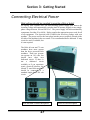
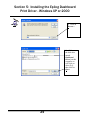
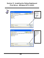
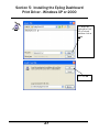
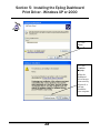
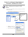
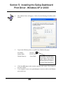
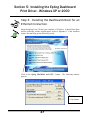
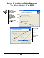
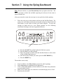
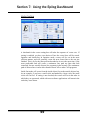
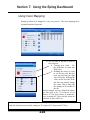
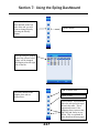
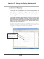
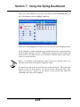
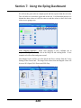
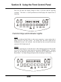
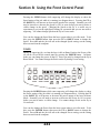
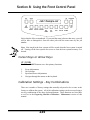
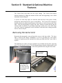
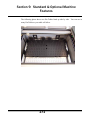
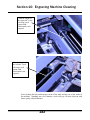
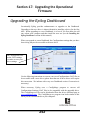
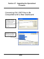
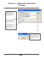
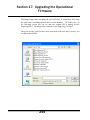
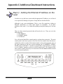
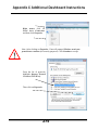
1
OWNER'S MANUAL FOR EPILOG MINI/HELIX - MODEL 8000 This manual can also be found in electronic format on the Epilog Dashboard Drivers and Documentation disk that came with your laser system. December 14, 2009 16371 Table Mountain Parkway Golden, CO 80403 Phone (303) 277-1188 Fax (303) 277-9669 Technical Support Direct Line: (303) 215-9171 Email Technical Support: [email protected] Technical Support Online: www.epiloglaser.com/service.htm www.epiloglaser.com/downloads.htm THIS PAGE WAS INTENTIONALLY LEFT BLANK ii Contents at a Glance Fire Warning!.......................................................................................................... ix Introduction ........................................................................................................... xi Epilog Laser Setup ................................................................................................. 1 Section 1: Safety ............................................................................................................................ 3 Section 2: Dos and Don’ts ........................................................................................................... 11 Section 3: Getting Started ............................................................................................................ 13 Section 4: Connecting the Laser to Your Computer.................................................................... 19 Section 5: Installing the Epilog Dashboard Print Driver - Windows XP or 2000 ....................... 21 Section 6: Quick Start & Easy Setup ........................................................................................... 49 Basic Operations .................................................................................................. 61 Section 7: Using the Epilog Dashboard ....................................................................................... 63 Section 8: Using the Front Control Panel .................................................................................. 127 Section 9: Standard & Optional Machine Features.................................................................... 139 Section 10: Engraving Machine Cleaning ................................................................................. 173 Section 11: Engraving Machine Calibration / Maintenance ...................................................... 187 Section 12: Speed and Power Recommendations...................................................................... 191 Section 13: Material Engraving Techniques.............................................................................. 199 Section 14: Material Suppliers................................................................................................... 223 Technical Support, Troubleshooting and Specifications ..................................... 229 Section 15: In Case of Difficulty ............................................................................................... 231 Section 16: Specifications.......................................................................................................... 237 Section 17: Upgrading the Operational Firmware ..................................................................... 245 APPENDIX A WARRANTY STATEMENT ................................................................. 257 APPENDIX B PRINTING FROM AUTOCAD............................................................. 259 APPENDIX C ADDITIONAL DASHBOARD DRIVER INSTRUCTIONS ........................ 265 INDEX................................................................................................................. 293 iii Table of Contents Fire Warning!.......................................................................................................... ix Introduction ........................................................................................................... xi How to Use This Owner’s Manual ........................................................................................ xi Epilog Laser Setup ................................................................................................. 1 Section 1: Safety ............................................................................................................................ 3 Laser Safety ............................................................................................................................ 3 Electrical Safety ...................................................................................................................... 5 Fire Safety ............................................................................................................................... 6 Safety Features and Regulatory Compliance .......................................................................... 7 Section 2: Dos and Don’ts ........................................................................................................... 11 DON’T!................................................................................................................................. 11 DO......................................................................................................................................... 12 Section 3: Getting Started ............................................................................................................ 13 Setting Up Your Laser System ............................................................................................. 13 Connecting the Exhaust ........................................................................................................ 14 Connecting Electrical Power................................................................................................. 17 Laser Cooling Requirements and Operating Temperatures.................................................. 17 Laser Cooling Requirements and Operating Temperatures.................................................. 18 Section 4: Connecting the Laser to Your Computer.................................................................... 19 Connecting the Laser to Your Computer .............................................................................. 19 USB Port ............................................................................................................................... 20 Ethernet Port ......................................................................................................................... 20 Section 5: Installing the Epilog Dashboard Print Driver - Windows XP or 2000 ....................... 21 Installing the Dashboard Driver Using a USB Connection and Cable ................................. 22 Installing the Dashboard Driver Using an Ethernet Connection and a Crossover Cable ..... 30 Section 6: Quick Start & Easy Setup ........................................................................................... 49 Artwork Setup ....................................................................................................................... 51 Job Setup............................................................................................................................... 54 iv Table of Contents Basic Operations .................................................................................................. 61 Section 7: Using the Epilog Dashboard ....................................................................................... 63 Advanced Tab ..................................................................................................................... 100 Color Mapping Tab............................................................................................................. 113 Additional Dashboard Driver Features ............................................................................... 123 Changing Dashboard Driver Defaults................................................................................. 125 Section 8: Using the Front Control Panel .................................................................................. 127 Keyboard Commands.......................................................................................................... 128 Loading Your Work ............................................................................................................ 137 Operation............................................................................................................................. 138 Job Storage.......................................................................................................................... 138 Section 9: Standard & Optional Machine Features.................................................................... 139 Auto Focus .......................................................................................................................... 140 Air Assist ............................................................................................................................ 142 The Task Plate..................................................................................................................... 144 Red Dot Pointer................................................................................................................... 145 Integrated Vacuum Table.................................................................................................... 145 Integrated Vector Grid ........................................................................................................ 146 Rotary Attachment .............................................................................................................. 149 Pin Table ............................................................................................................................. 161 1.5 Inch High Resolution Lens ........................................................................................... 172 Section 10: Engraving Machine Cleaning ................................................................................. 173 Cleaning - Important!.......................................................................................................... 173 Fire Warning!...................................................................................................................... 173 Cleaning the Exhaust .......................................................................................................... 183 Laser Tube .......................................................................................................................... 185 Section 11: Engraving Machine Calibration / Maintenance ...................................................... 187 Calibration Settings Using the Keyboard ........................................................................... 187 v Table of Contents Section 12: Speed and Power Recommendations...................................................................... 191 Engraving Speed ................................................................................................................. 191 Engraving Power................................................................................................................. 191 Recommendations............................................................................................................... 192 Multiple Passes ................................................................................................................... 193 30 Watt - Epilog Mini/Helix ............................................................................................. 194 40 Watt - Epilog Mini/Helix ............................................................................................. 195 50 Watt - Epilog Mini/Helix ........................................................................................... 196 60 Watt - Epilog Mini/Helix ........................................................................................... 197 75 Watt - Epilog Helix .................................................................................................... 198 Section 13: Material Engraving Techniques.............................................................................. 199 Acrylic................................................................................................................................. 199 Fire Warning!...................................................................................................................... 199 Anodized Aluminum........................................................................................................... 202 Brass - Painted .................................................................................................................... 202 Glass.................................................................................................................................... 204 Notary Seals - Delrin .......................................................................................................... 206 Plastic .................................................................................................................................. 207 Rubber Stamps .................................................................................................................... 209 Wood................................................................................................................................... 217 Section 14: Material Suppliers................................................................................................... 223 Technical Support, Troubleshooting and Specifications ..................................... 229 Section 15: In Case of Difficulty ............................................................................................... 231 Contacting Technical Support............................................................................................. 231 Avoiding Common Print Problems..................................................................................... 232 Section 16: Specifications.......................................................................................................... 237 Epilog Mini 18 x 12 Specifications .................................................................................... 237 Epilog Mini 24 x 12 Specifications .................................................................................... 238 Epilog Helix Specifications ................................................................................................ 239 Compatibility ...................................................................................................................... 240 Recommended PC............................................................................................................... 240 Other Computer Hardware Recommendations ................................................................... 242 About The Laser ................................................................................................................. 243 Federal Communications Commission (FCC) Notice ........................................................ 244 vi Table of Contents Section 17: Upgrading the Operational Firmware ..................................................................... 245 Upgrading Your Firmware.................................................................................................. 245 Installing New Firmware onto Your Computer .................................................................. 246 Transferring New Firmware from Your Computer to Your Laser ..................................... 248 Upgrading the Epilog Dashboard........................................................................................ 252 Converting Old .DAT Files to Be Compatible with a New Dashboard.............................. 253 APPENDIX A WARRANTY STATEMENT ................................................................. 257 APPENDIX B PRINTING FROM AUTOCAD............................................................. 259 APPENDIX C ADDITIONAL DASHBOARD DRIVER INSTRUCTIONS ........................ 265 Dashboard Driver Installation for USB Connection Using Windows Vista....................... 265 Windows Vista Dashboard driver installation for Ethernet connection ............................. 268 Installing the Dashboard Driver when the AutoRun Feature Does Not Start when using Windows XP or 2000.......................................................................................................... 285 Installing the Dashboard driver when the AutoRun feature Does Not Start when using Windows Vista.................................................................................................................... 287 Windows 7: Setting up the TCP/IP Address in the Computer........................................... 288 INDEX................................................................................................................. 293 vii Table of Contents THIS PAGE WAS INTENTIONALLY LEFT BLANK viii Fire Warning! Your laser system uses a high intensity beam of light that can generate extremely high temperatures when it comes into contact with the material being engraved, marked or cut. Some materials are extremely flammable and can easily ignite and burst into open flame setting the machine afire. This open flame is very dangerous and has the potential to destroy not only the machine, but the building in which it is housed. Experience shows that vector cutting with the laser has the most potential to create an open flame. Many materials are susceptible to igniting, but acrylic, in all its different forms, has been shown to be especially flammable when vector cutting with the laser. Please read the following warnings and recommendations and follow them closely at all times! NEVER let the laser system operate if it will be unattended. KEEP the area around the machine clean and free of clutter, combustible materials, explosives, or volatile solvents such as acetone, alcohol, or gasoline. ALWAYS keep a properly maintained and inspected fire extinguisher on hand. Epilog recommends a Halotron fire extinguisher or a multi-purpose dry chemical fire extinguisher. The Halotron extinguishers are more expensive than a dry chemical, but offer certain advantages should you ever need to use an extinguisher. The Halotron extinguisher discharges a clean, easily removable substance that is not harmful to the mechanics or wiring of the laser system. The dry chemical extinguisher discharges a sticky, corrosive powder that is very difficult to clean up. ALWAYS use air assist when vector cutting. BE CAREFUL! when vector cutting. Many materials have the potential to burst suddenly into flames – even materials that may be very familiar to the user. Always monitor the machine when it is operating. KEEP YOUR LASER SYSTEM CLEAN – A build up of cutting and engraving reside and debris is dangerous and can create a fire hazard in its own right. Keep your laser system clean and free of debris. Regularly remove the vector grid to clean any small pieces that have fallen through the grid. ix Fire Warning! SEE PREVIOUS PAGE x Introduction How to Use This Owner’s Manual Thank you for purchasing an Epilog Mini/Helix 8000 Laser System. Your Epilog system has been designed to be easy to operate, but you will utilize it to its fullest potential by taking some time to read this owner’s manual prior to use. You will be ready to use the Epilog laser system as soon as you read the first six sections. Then you can refer to topics in the remaining sections, as you work. Structure of the Manual Part I: Epilog Mini/Helix Setup Sections 1 through 6 explain how to uncrate and set up your Epilog system, important safety information you need to know before you use it, the Do’s and Don’ts of operating the laser, configuring your computer to run the Epilog Dashboard print driver, configuring CorelDraw, and a brief user’s guide to running your first job. Part II: Epilog Mini/Helix Basic Operations Sections 7 through 14 explain Using the Epilog Dashboard Print Driver, basic Epilog laser operations and maintenance, machine features, speed and power recommendations, material engraving techniques, and material suppliers. Part III: Troubleshooting, Service and Specifications Sections 15 through 17 assist with problem troubleshooting, service information, system specifications and firmware upgrade instructions. APPENDIX A Epilog Warranty Information. APPENDIX B Printing from AutoCAD. APPENDIX C Additional Dashboard Print Driver Instructions. INDEX xi Introduction Icons Used in this Manual Look for these symbols to help you find valuable information throughout the text: Sometimes the right perspective on a procedure is essential to success. This icon Flags a Quick Note regarding the task at hand. This Icon signifies places to look for additional information to assist with the topic currently being discussed. This Icon highlights current contact information for receiving help. This Icon signifies advice you can try out with your machine right away. This Icon signifies advice you can try that will save you significant time. Running into trouble can be detrimental to your success so we’ve marked Warnings and Cautions with this Icon. Indicates Epilog Helix Model 8000 24x12 Specific Information Indicates Epilog Mini Model 8000 18x12 Specific Information xii Introduction Indicates Epilog Mini Model 8000 24x12 Specific Information Indicates pages including information regarding connecting your laser system to your computer using an USB connection. Indicates pages including information regarding connecting your laser system to your computer using an Ethernet connection. Indicates the potential for fire danger when operating the laser. xiii Introduction THIS PAGE WAS INTENTIONALLY LEFT BLANK xiv Manual Epilog Laser Setup 1 THIS PAGE WAS INTENTIONALLY LEFT BLANK 2 Section 1: Safety In This Section Laser Safety Electrical Safety Fire Safety Safety Features And Regulatory Compliance Laser Safety The Epilog Model 8000 Laser System is a Class 3R laser product, as defined in International Standard IEC 60825-1. The Epilog Model 8000 complies with 21 CFR 1040.10 and 1040.11, the Federal Performance Standards for Light-Emitting Products, except for deviations pursuant to Laser Notice No. 50, dated July 16, 2001. The Center for Devices and Radiological Health, of the US FDA, issued Laser Notice No. 50 to permit manufacturers to classify and manufacture their products in accordance with the International Standard. The output of the embedded high-power CO2 engraving laser is fully contained. The laser cabinet has safety interlocks that turn the laser off if the door is opened during operation, and no special precautions are necessary to operate the highpower laser safely. However, the visible output beam of the Laser Diode Pointer (Red Dot Pointer) is accessible to the operator. While this device employs the same technology as the familiar laser pen-pointers, like them it is potentially hazardous if its beam is directed into the eye. We have made every effort to make the Laser Diode Pointer (Red Dot Pointer) as safe as possible. Its beam path is located well inside the cabinet, and under normal conditions, no hazardous levels of laser radiation can escape. 3 Section 1: Safety The operator of the Epilog Model 8000 should observe the following general precautions: DO NOT disassemble the machine or remove any of its protective covers while the unit is plugged in. DO NOT attempt to defeat the door interlocks. DO NOT view directly into the beam of the Laser Diode Pointer (Red Dot Pointer). DO NOT operate the Laser Diode Pointer (Red Dot Pointer) without the machine’s focus lens in place. If the unfocused beam strikes a reflective surface, it could be directed out of the cabinet. Caution – Use of controls or adjustments or performance of procedures other than those specified herein may result in hazardous radiation exposure. * * * The standard reference for laser safety is the American Standard for the Safe Use of Lasers, Z136.1-2000, developed by the American National Standards Institute (ANSI). This reference is the basis for many of the federal regulations for laser and laser system manufacturers, and for the Occupational Safety and Health Administration (OSHA) laser safety guidelines. It contains detailed information concerning proper installation and use of laser systems. While the ANSI standard itself does not have the force of law, its recommendations, including warning signage, training, and the designation of a laser safety officer, may be compulsory under local workplace regulations when operating laser systems above Class I. It is the operator’s responsibility to ensure that the installation and operation of the Epilog Model 8000 Laser System is performed in accordance with all applicable laws. Copies of ANSI Standard Z136.1-2000 are available from Epilog Corporation or from: Laser Institute of America 12424 Research Parkway, Suite 125 Orlando, FL 32826 (407) 380-1553 4 Section 1: Safety Electrical Safety The AC input power to the Epilog Model 8000 Laser System is potentially lethal and is fully contained within the cabinet. DO NOT open any of the machine’s access panels while the unit is plugged in. Opening a panel may expose the operator to the unit’s AC input power. DO NOT make or break any electrical connections to the system while the unit is turned on. 5 Section 1: Safety Fire Safety Laser cutting and engraving systems represent a significant fire hazard. Most engraving materials are inherently combustible, and while the objective of most cutting and engraving operations is to vaporize material without burning, it is easy to ignite a flame. Usually this is a simple “flare” of burning gases, issuing from the focused spot on the work piece, which follows the moving spot and which extinguishes itself as soon as the laser beam is modulated off. But should the work piece actually be set on fire, the fire must be extinguished by the operator at once, or the machine will be seriously damaged or destroyed! Experience shows that vector cutting with the laser has the most potential to create an open flame. Many materials are susceptible to igniting, but acrylic, in all its different forms, has been shown to be especially flammable when vector cutting with the laser. Please read the following warnings and recommendations and follow them closely at all times! NEVER let the laser system operate if it will be unattended. KEEP the area around the machine clean and free of unnecessary clutter, combustible materials, explosives, or volatile solvents such as acetone, alcohol, or gasoline. ALWAYS keep a properly maintained and inspected fire extinguisher on hand. Epilog recommends a Halotron fire extinguisher or a multi-purpose dry chemical fire extinguisher. The Halotron extinguishers are more expensive than a dry chemical, but offer certain advantages should you ever need to use an extinguisher. The Halotron extinguisher discharges a clean, easily removable substance that is not harmful to the mechanics or wiring of the laser system. The dry chemical extinguisher discharges a sticky, corrosive powder that is very difficult to clean up. ALWAYS use air assist when vector cutting. BE CAREFUL! When vector cutting. Many materials have the potential to burst suddenly into flames – even materials that may be very familiar to the user. Always monitor the machine when it is operating. KEEP YOUR LASER SYSTEM CLEAN – A build up of cutting and engraving reside and debris is dangerous and can create a fire hazard in its own right. Keep your laser system clean and free of debris. Regularly remove the vector grid to clean any small pieces that have fallen through the grid. 6 Section 1: Safety Safety Features and Regulatory Compliance Epilog has incorporated specific safety features into the Model 8000 Laser System in order to meet the requirements of 21 CFR 1040 and the International Standard IEC 60825-1. These safety features include: A safety enclosure (cabinet), which fully encloses the engraving laser and its beam path. Dual redundant interlock systems that turn off the engraving laser when the window is opened. A visible emission indication when the Laser Diode Pointer (Red Dot Pointer) is operating. There is an LED indicator on the machine’s front panel. 21 CFR 1040 and IEC 60825-1 require that certification, identification, and warning labels be placed on laser products. Reproductions of labels on the Epilog Model 8000 Laser System follow, with their locations specified: 1. Certification/Identification Label. This engraved plate is located on the rear of the machine’s cabinet. The example shown is for the Model 8000/25 product having an 18 inch by 12 inch engraving area. Epilog Corporation 500 Corporate Circle, Suite L Golden, CO 80401 USA Model Number: 8000 Laser System Serial Number: 8025-0400011812 Date of Manufacture: March 2004 Class 3R Laser Product This product complies with 21 CFR 1040.10 and 1040.11 except for deviations pursuant to Laser Notice No. 50, dated July 26, 2001. This product complies with IEC 60825-1: 2001. 7 Authorized Representative: Consultants Europe bv PO Box 5047 1380 GA Weesp The Netherlands Tel.: 31-294-483355 Fax.: 31-294-414687 E-Mail: [email protected] Mass: 35 kg max Section 1: Safety 2. Warning Label. This label is located on the rear of the machine’s cabinet, below the Certification/Identification Label above. 3. Explanatory Label. This label identifies the classification of the Model 8000 in accordance with IEC 60825-1. It is located on the rear of the machine’s cabinet, beside the Warning Label above. LASER RADIATION AVOID DIRECT EYE EXPOSURE CLASS 3R LASER PRODUCT 4 mW CW MAXIMUM 630 - 680 nm 4. Non-interlocked Protective Housing Safety Labels (4). Two of these labels are located on the rear of the machine; beside the edges of each of the cabinet’s end covers. The other two labels are located on the cabinet walls under the covers, so that they are visible when the covers have been removed. CAUTION - CLASS 4 VISIBLE AND INVISIBLE LASER RADIATION WHEN OPEN AVOID EYE OR SKIN EXPOSURE TO DIRECT OR SCATTERED RADIATION 8 Section 1: Safety 5. Defeatably-interlocked Protective Housing Safety Label. This label is located on the machine’s cabinet door, in the upper left-hand corner. CAUTION - CLASS 4 VISIBLE AND INVISIBLE LASER RADIATION WHEN OPEN AND INTERLOCKS DEFEATED AVOID EYE OR SKIN EXPOSURE TO DIRECT OR SCATTERED RADIATION 6. Aperture Safety Label. This label is located on the steering-mirror cover inside the machine’s cabinet, beside the aperture where the laser beams enter the cabinet. 7. Electrical Safety Label. This label is located on the access panel on the rear of the machine’s cabinet. HIGH VOLTAGE INSIDE CABINET DISCONNECT POWER BEFORE OPENING PANEL 8. Fire Safety Label. This label is located on the machine’s cabinet door, in the upper right-hand corner. FIRE HAZARD DO NOT OPERATE MACHINE UNATTENDED 9 Section 1: Safety 9. Fire Warning Label This fire hazard label is located on the left and right sides of the top access door of your laser system: DANGER FIRE HAZARD DO NOT OPERATE MACHINE UNATTENDED USE EXTREME CAUTION WHEN CUTTING FLAMMABLE MATERIALS SUCH AS WOOD OR ACRYLIC. A PROPERLY MAINTAINED FIRE EXTINGUISHER SHOULD BE KEPT NEAR THE MACHINE AT ALL TIMES. EPILOG RECOMMENDS A CO2 FIRE EXTINGUISHER. PERIODICALLY REMOVE THE VECTOR CUTTING GRID AND REMOVE DEBRIS FROM THE TABLE PAN. PERIODICALLY REMOVE THE EXHAUST TUBE ADAPTER FROM THE BACK OF THE MACHINE AND REMOVE ANY DEBRIS FROM THE EXHAUST PORT. REFER TO THE USERS MANUAL FOR ADDITIONAL INFORMATION REGARDING FIRE SAFETY 10 Section 2: Dos and Don’ts In This Section Operating Dos and Don’ts DON’T! NEVER operate the machine without a properly operating vent to the outside! Most material will only produce an irritating smoke when engraved. Some materials, including but not limited to paint, varnish, composition board and plastics, produce compounds that can be harmful if concentrated. A properly installed vent is the only way to ensure that problems do not occur. NEVER engrave or cut any material containing PVC or vinyl. When engraved, a corrosive agent is produced that will destroy your machine. Your warranty will be void if your machine is damaged by corrosion from engraving or cutting PVC or Vinyl. NEVER operate your machine unattended. There is a significant risk of fire if the machine is set improperly, or if the machine should experience a mechanical or electrical failure while operating. NEVER vector cut any material while the machine is unattended. Because vector cutting moves relatively slowly compared to raster engraving, a tremendous amount of heat is applied to the material being cut. This build up of heat can cause significant fire risk and the machine should always be monitored. Additionally, the air assist should always be turned on when vector cutting to reduce the risk of fire. NEVER operate with any of the covers or enclosures removed, and never modify the enclosure. The laser beam is invisible! 11 Section 2: Dos and Don’ts DO Please allow a few minutes a week for cleaning your machine. Just a small amount of effort at the end of the week will pay off with years of trouble free operation of your machine. See the Engraving Machine Cleaning section of this manual for specifics. 12 Section 3: Getting Started In This Section Setting Up Your Laser System Connecting The Exhaust Connecting The Electrical Power Laser Cooling Requirements And Operating Temperatures Setting Up Your Laser System Setting up your Epilog Laser System is easy to do! If you’ve ever installed a paper printer on your computer, this is almost that easy. You will need to do the following to use your machine: Remove it from the crate Connect the exhaust system to your laser Connect electrical power Connect the laser to your computer using a USB or Ethernet cable Install the Epilog Dashboard print driver onto your computer You may need a contractor to install the exhaust. This must be done PRIOR to installation of the laser system. Time Saver: PLEASE DO NOT throw away the box and all packaging, you may need it later. This will save considerable time trying to repackage the machine for routing to different locations. 13 Section 3: Getting Started Connecting the Exhaust It is mandatory that an exhaust blower is hooked up and operating whenever your laser system is running a job. The exhaust blower removes the dust, debris and smell from the engraving cavity and exhausts it to the outside of the building. You should never operate your laser system without a properly working exhaust. Prior to the installation of the laser system, a contractor should install the exhaust system. The blower should be mounted outside your building for noise considerations. The blower should not be more than twenty feet (6 meters) from the laser. You should provide a metal duct (flexible aluminum or galvanized sheet metal) from the blower to the laser. All Epilog model 8000 laser systems require an exhaust fan that is rated at a minimum of 400 CFM at 6” of static pressure 680 M3 /hr. at 150 mm of static pressure. Note: Remember to put the blower switch for the laser system in an obvious and accessible place so it can be routinely switched on prior to using the engraver. Please connect the exhaust blower to the laser as shown below and on the following pages. Warning: It’s important that either rigid or flexible metal ducting be used for all connections leading to and from the laser system and the exhaust fan. Vinyl, plastic, or any type of “soft” ducting is potentially flammable and should NEVER be used. Flexible aluminum duct or galvanized sheet metal duct is readily available for your ducting needs. In the United States flexible aluminum ducting can be acquired from the following location: Grainger http://www.grainger.com/ McMaster-Carr http://www.mcmaster.com/ Supplier Size Part Number Grainger McMaster-Carr 4” 4” 3C591 5525K34 14 Cost (15 foot length) $17.52 $15.90 Section 3: Getting Started Epilog Exhaust Blower Connections As part of the unpacking process you will find a 4” (100mm) exhaust port in the accessories kit. This part needs to be attached to the rear of the Mini chassis before connecting the Exhaust blower to the Mini. The mounting screws for the exhaust port are in the mounting holes in the chassis. Remove these four screws, align the exhaust port to the mounting holes and secure the exhaust port with the four screws. Mounting Screws (4 each) - remove from chassis before installing exhaust port. Exhaust Port (from accessories box) Once the exhaust ports are installed on the back of the laser system, use the flexible aluminum or galvanized sheet metal ducting to connect the laser system to the intake side of the exhaust fan. Then connect the exhaust side of the exhaust fan to the metal duct leading outside. Check your exhaust system for leaks. Most small leaks can be remedied with duct tape. DO NOT OPERATE your laser with inadequate or leaking exhaust. 15 Section 3: Getting Started The drawings below show the typical exhaust setup. The top drawing shows the exhaust on the roof and the bottom drawing shows the exhaust fan near the machine. Where the exhaust fan is placed is a choice of personal preference. Some users like the exhaust fan outside because of noise considerations. Exhaust Blower Roof or exterior wall 4” (100 mm) flexible aluminum duct or rigid galvanized sheet metal (Do not use vinyl, plastic or “soft” flexible duct). Roof or exterior wall 4” (100 mm) flexible aluminum duct or rigid galvanized sheet metal (Do not use vinyl, plastic or “soft” flexible duct). Exhaust Blower 16 Section 3: Getting Started Connecting Electrical Power What voltage should be supplied to operate a Mini or Helix? All Epilog laser systems have an auto-switching power supply that detects the incoming voltage and automatically switches itself to operate properly at any singlephase voltage between 100 and 240 VAC. The power supply will also automatically compensate for either 50 or 60 Hz. Epilog supplies the appropriate power cord for all of our equipment. The electrical cord is found in the accessory package with your machine. The power cord for the laser plugs into the power receptacle located on the left side of the machine in the rear corner. It is recommended that a dedicated 15 amp circuit be used if available, but it is not required. The Helix 60 watt and 75 watt machines draw more current than the lower powered Helix machines. These two systems can operate on 110 volts, but should have their own dedicated circuit. If there is not a dedicated circuit available, or if you experience erratic electrical behavior, the 60 and 75 watt Helix machines should be connected to a standard single phase 220 volt circuit. Helix and Mini 24 Power Receptacle 17 Mini 18 Power Receptacle Section 3: Getting Started Laser Cooling Requirements and Operating Temperatures All Epilog laser systems use air-cooled laser tubes. Laser technology is such that the laser tubes generate a lot of excess heat and the tubes must be cooled in order for them to operate correctly. There are cooling fans located on the top of the laser and cooling vents that are located all along the back of the systems. The fans and vents should always be clear of restrictions and should never be covered. Warning: The cooling fans and vents should never be covered or blocked in any way. Lasers that overheat will not operate properly and may begin to produce erratic laser output or possibly complete failure. Use compressed air to remove any dust buildup on the fans or the laser cooling fins. Cooling Fans – Do Not Cover Cooling Vents – Do Not Block. Ambient air temperature where the laser system is operating should not exceed 90 degrees F (32 C). Operating in an environment where the ambient air temperature is above 90 degrees F (32 C) will void the Epilog warranty. 18 Section 4: Connecting the Laser to Your Computer In This Section Connecting the Laser to Your Computer USB Port Ethernet Port Connecting the Laser to Your Computer All Epilog systems are designed to be used with Microsoft Windows XP, 2000 or 32 bit Vista operating systems. There are two different methods of connecting the laser to your computer. You can connect to your computer with either an Ethernet cable or a USB cable. Choose either the USB or Ethernet cable – but do not plug both cables into the laser at the same time! Many users, especially those that do not have a lot of experience installing printers or other devices to their computers, find the USB cable is the easier method of connection. If your laser is going to be a long distance from your computer, you will be better off using the Ethernet cable. If you are using the USB port, make sure the laser system is turned off before connecting the USB cable from your computer (it doesn’t matter if the computer is on or off). For your convenience, Epilog includes both an Ethernet crossover cable and a USB cable in the Accessories kit. 19 Section 4: Connecting the Laser to Your Computer TEST Port (not intended for consumer use). This drawing shows the data port connections that are located on the back of the laser system. Ethernet Port USB Port USB Port Connect to laser A USB cable is included in the accessory kit. The USB port is located on the right side of the machine, near the rear. USB cables have different connectors on each end. Turn the laser Off, then connect this end to the laser and connect the other end into any available USB port at the back of your computer. After connecting the USB cable, turn the laser back on. Your computer will recognize a new USB device and walk you through the Dashboard print driver installation (detailed Dashboard installation instructions are found in later sections of this manual). Ethernet Port The Ethernet Port is a standard 10BaseT connection. A crossover cable (included in the accessories kit) plugs into the Ethernet port. The Ethernet port is located on the right side of the machine, near the rear. Your Epilog laser has all of the versatility of a Network capable peripheral. As such, there are many different ways that the laser can be connected to a computer or a network. A direct connection using a crossover cable is the only method that will be described in this manual. Plug the cable into the Ethernet port on the laser and then plug the other end into the Ethernet port on the back of your computer. 20 Section 5: Installing the Epilog Dashboard Print Driver - Windows XP or 2000 In This Section This section applies to Windows XP/2000 only. Installation instructions for Windows Vista are found in Appendix C – Additional Dashboard Print Driver Instructions, of this manual Installing the Dashboard Print Driver Using an USB Connection Installing the Dashboard Print Driver Using an Ethernet Connection and a Crossover Cable The Epilog Dashboard is the print driver that allows your computer to talk to your Epilog laser system when either the USB or Ethernet Crossover cables are connected. The Dashboard is designed for use with Windows XP, Windows 2000 and the 32 bit version of Windows Vista (32 bit is the standard version). The driver is included in the accessories kit on a CD-ROM or on our web site - www.epiloglaser.com. You will need to install the Dashboard by following the procedures on the following pages. There are two ways of installing the Epilog Dashboard. Both methods are similar, and your computer configuration will determine which method to use. 1. 2. The first method is using the USB connection. This is very straight forward and easy to accomplish. The second method is using the Ethernet connection. This process is very similar to the USB installation, but there are a couple of important additional steps. Instructions for installing the Dashboard using the Windows Vista operating system are included in the appendix. The Epilog Mini, Helix and EXT laser systems all use the same Dashboard print driver. The driver will identified as the “Epilog Engraver Win32” when it is installed onto your computer. 21 Section 5: Installing the Epilog Dashboard Print Driver - Windows XP or 2000 Installing the Dashboard Driver Using a USB Connection and Cable There are a couple of different ways to install the Dashboard print driver when using the USB connection, but we have found the following sequence is very easy for users who are installing a print driver for the first time. Please read the first four steps of this procedure before starting the installation process. 1. 2. Turn off your laser system (keep your computer powered on). Insert the Epilog Dashboard driver disk into your CD or DVD drive on your computer. The following window will appear: a) Close this screen by clicking on the red X 3. Connect the USB cable to both your system and your computer. The USB cable is provided in the Accessories Kit that came with your machine. 22 Section 5: Installing the Epilog Dashboard Print Driver - Windows XP or 2000 4. Turn your laser system on. After a few moments the following window will appear, and you can now proceed with installing the Dashboard print driver. 5. Click on No, not this time, then click on Next >. 6. When this window appears, click on Install from a list or specific location (Advanced) then click Next>. 23 Section 5: Installing the Epilog Dashboard Print Driver - Windows XP or 2000 7. Click on Don’t Search. I will choose the driver to install., then click Next>. 8. Click on Have Disk… 24 Section 5: Installing the Epilog Dashboard Print Driver - Windows XP or 2000 9. Click on Browse… 10. Click on the disk drive named Dashboard Driver [on this computer we will click on drive (D:)], then click on Open. 25 Section 5: Installing the Epilog Dashboard Print Driver - Windows XP or 2000 11. Click on the drivers folder, then click Open. 12. Click on the Epilog Driver X.XX, then click Open. 26 Section 5: Installing the Epilog Dashboard Print Driver - Windows XP or 2000 13. Insure the EpilogWin32.inf file is selected and then click on Open. 14. Click OK. 27 Section 5: Installing the Epilog Dashboard Print Driver - Windows XP or 2000 15. Click Next>. 16. Click Continue Anyway. While the Dashboard driver has not been tested by Microsoft, it will not destabilize your computer. 28 Section 5: Installing the Epilog Dashboard Print Driver - Windows XP or 2000 17. Click Finish. That’s it! You should see a balloon in the lower right corner of your computer screen indicating that new hardware has been found and is ready to use. You’re now ready to print to your laser system! 29 Section 5: Installing the Epilog Dashboard Print Driver - Windows XP or 2000 Installing the Dashboard Driver Using an Ethernet Connection and a Crossover Cable (Skip this part if you are using a USB cable described in the previous section.) There are three easy steps involved in setting up the laser and computer system to operate through an Ethernet connection: 1. 2. 3. Setting the Ethernet IP Address on the laser, Setting up the computer’s TCP/IP Address, and Dashboard Driver Installation. Note: The following instructions work only for a direct connection from the computer to the Epilog laser using a Crossover cable. This procedure does not work with a hub or a server. For Ethernet connections that require a hub, server, or multiple machines/computers, please consult with your network administrator. Hardware Requirements A 10Base-T or 10/100Base T Ethernet network card installed in your computer. All brand name computers that have been built in the last couple of years should have come standard with an Ethernet card installed. A crossover cable connecting your computer to the laser (included in your accessories kit). Please Note! - The crossover cable looks almost exactly like a standard straightthrough network cable, but they have different purposes for making network connections. Normally, the crossover cable should only be used when connecting the Epilog laser directly to your computer. Ask your network administrator for assistance if you are unsure of which type of cable you have. It is a good idea to place a tag or label on the cable indicating if it is a crossover cable or standard (CAT5) straight-through cable. 30 Section 5: Installing the Epilog Dashboard Print Driver - Windows XP or 2000 Step 1: Setting the Ethernet IP Address on the Laser In order to set up the laser system with the appropriate IP Address, you will need to set-up the laser through a sequence of steps that are described below. Although it may seem intimidating if this is your first experience setting up Ethernet connections, it’s really quite simple to accomplish. If you have problems, don’t panic! You cannot do anything wrong that starting over will not fix! There are three network protocols that will need to be set. They are set in the following order. 1. 2. 3. IP ADDRESS SUBNET MASK GATEWAY You will use the Mini/Helix control panel to set these three protocols. The main control panel on the laser systems is used for all of the common laser functions as explained in later sections of this manual, and it is also used to program some of the setup functions of the laser system including the IP ADDRESS, SUBNET MASK, an the GATEWAY. In order to program these setup functions we assign a set of “hidden” numbers to the keys on the control panel. The diagram below shows which control panel keys are associated with each hidden number needed to set the network protocols. GO STOP Job:1.Sample.cdr DATA 0 RESET 1 2 SPEED POWER UP POINTER 8 9 3 4 5 6 7 SET HOME X/Y OFF JOB FOCUS DOWN Control Panel with hidden numbers for use with Network Settings 31 Section 5: Installing the Epilog Dashboard Print Driver - Windows XP or 2000 IP ADDRESS 1. 2. 3. 4. To set the IP Address press the GO and POINTER buttons simultaneously on the control panel. You will see “FUNCTIONS MENU” displayed on the control panel LCD screen. Press the GO button. - “SERIAL #” will appear on the screen. This is a factory set number and corresponds to the serial number of the laser system. You should not change this serial number. Press the GO button again. – “IP ADDRESS” will appear on the screen. Press the GO button again. - The factory set IP address will appear on the screen. It will look something like this: “192.168.003.004”, with a flashing box over the 1 in 192. Note – This procedure uses 192.168.003.004 as the sample IP Address. Machines leaving the Epilog factory have this IP Address preset so you do not have to change anything unless you want to use a different address. 5. If you want to change the IP Address, please follow these instructions: a) If you want to change the 1 in 192 to any other number, simply press the “hidden” number key for that number. For example, if you want to change the 1 (in 192) to a 4, press the X/Y Off key. After pressing the X/Y Off key the 1 will change to a 4. When a number key is pressed, the flashing box will automatically shift right to the next number in that three number group. b) At this point, press the appropriate key for the second number (if you want to keep the 9 a 9, you must press the POINTER key). c) Finally, press the appropriate key for the third number. d) After pressing the key for the third number the flashing box will go back to the first number – it WILL NOT shift to the next set of three numerals. If you want to move to the next group of three numbers 32 Section 5: Installing the Epilog Dashboard Print Driver - Windows XP or 2000 simply press the GO button. Pressing GO will cause the flashing box to shift right to the next three number group. Repeat this process to change any of the numbers. Note – There is no way to simply scroll through the IP Address numbers and skip over single numbers you do not want to change. You can skip groups of three by pressing GO, but skipping single numbers cannot be done. There is also no way to move the cursor (flashing box) backwards. The cursor scrolls through each three number group continuously until you press the GO button, where it will then go to the next three number groups. The following example shows you how to change the number 196 to 195. When you start with the flashing box over the 1, press the SPEED button (this keeps the 1 a 1 and allows you to move to the next numeral). The flashing box will shift to the 9, where you will press the “Pointer” button (it will stay a 9 and the flashing box will shift right to the 6). Lastly, we want to change the 6 to a 5. Press the “Job” button. This will change the 6 to a 5 (it will also move the flashing box back to the 1 where you first started). If you now have the number you want to keep (195) and you are ready to move to the next three numeral set, pressing the GO button will get you there. 6. e) Repeat this process for all of the number groups to get the IP Address you need. After all the IP address numbers have either been changed or verified as the ones you need, press GO again – this will bring the SUBNET MASK screen. 33 Section 5: Installing the Epilog Dashboard Print Driver - Windows XP or 2000 SUBNET MASK Press GO again to see the SUBNET MASK settings. Use the same process of number selection using the keypads to select the appropriate number for the SUBNET MASK. Note: If you are using the cross-over cable provided by Epilog, set the “SUBNET MASK” to: “255.255.255.0” After you have set the “SUBNET MASK”, Press GO again. GATEWAY You will now see “GATEWAY”, Press GO again. The GATEWAY setting can be set using the same process of number selection using the key pads to select the appropriate numbers for “GATEWAY”. Note: The GATEWAY address is not required if you are using the provided cross over cable. You can leave it at the factory preset. If you are running your laser through a network, you will need to set the laser GATEWAY numbers to correspond to your network. At the end of the programming process, the laser will prompt you to either SAVE or NO (Not Save) the numbers you have applied. The Screen will look like: Save – GO, No- STOP Press the GO button to save the changes you made to the network settings. Press the STOP button if you do not want to save the changes and you want to return to the factory default. If at any time in the programming process you want to stop or restart, press the STOP button. This will take you out of the programming functions. If you want to restart the programming process, simultaneously press GO and POINTER to get back to the start of the Function Menu. 34 Section 5: Installing the Epilog Dashboard Print Driver - Windows XP or 2000 Step 2: Setting up the Computer’s TCP/IP Address Once you have set the IP Address on the laser you will need to set the TCP/IP Address in your computer. 1. From the Start menu at the bottom of your computer monitor screen select Start | Control Panel | Network Connections. Right mouse click on the Local Area Connections icon, then click on Properties. 2. Highlight the Internet Protocol (TCP/IP) option. 3. Then click on Properties. 35 Section 5: Installing the Epilog Dashboard Print Driver - Windows XP or 2000 4. The window below will appear. Select Use the following IP address radio button. 5. Type in the following (leave everything else blank on this page). 6. 7. IP Address Subnet Mask 192 168 3 3 255 255 255 0 Default Gateway Leave blank This number is not an error -the last digit of the IP address in this window only must be different than the IP address set in the Epilog Mini/Helix. Click the OK button in this window and then click on the Close button in the next window. Your computer is now set to print through a crossover cable to the Ethernet port on the laser. 36 Section 5: Installing the Epilog Dashboard Print Driver - Windows XP or 2000 Step 3: Installing the Dashboard Driver for an Ethernet Connection: Insert the Epilog Laser CD into your computer’s CD player. It should Auto-Start and the following window should appear (refer to Appendix C if the AutoRun feature does not bring up the following screen): Click on the Epilog Mini/Helix and EXT… button. The following window appears: 1. Click on the Unzip button. 37 Section 5: Installing the Epilog Dashboard Print Driver - Windows XP or 2000 NOTE - When you Unzip the driver files they will be unzipped into the c:/Epilog_Driver directory. Do not move them from this directory. The installation process looks for them in this directory later on in the process. The following window will appear: Click on OK and the following window appears: Click the Next> button to continue. 38 Section 5: Installing the Epilog Dashboard Print Driver - Windows XP or 2000 Select Local printer attached to this computer. Deselect Automatically detect and install my Plug and Play printer. Click Next> button to continue. Click on Create a new port: . Use the scroll button to select TCP/IP Port. Click Next> to continue. 39 Section 5: Installing the Epilog Dashboard Print Driver - Windows XP or 2000 Click Next> to continue. Enter the same IP Address that you set using the Mini/Helix keyboard (Step 1 in this procedure). It is important that the IP addresses be the same in both places, but the format of the numbers looks a little different. In the control panel the IP Address will look like this: 192.168.003.004. When you enter the IP Address in this window, you do not need the zeros, and the address will look like this: 192.168.3.4. 40 Section 5: Installing the Epilog Dashboard Print Driver - Windows XP or 2000 Click the Custom button, and then Settings. Set Protocol to LPR. This is a very important step. Your download time will be greatly increased if LPR is not selected. Type Legend in the Queue Name box. Click OK to continue. 41 Section 5: Installing the Epilog Dashboard Print Driver - Windows XP or 2000 Click Next> to continue. Click Finish to continue. 42 Section 5: Installing the Epilog Dashboard Print Driver - Windows XP or 2000 Click Have Disk… Click on Browse. 43 Section 5: Installing the Epilog Dashboard Print Driver - Windows XP or 2000 There are multiple drivers on this disc for different Epilog systems. Select Epilog Driver X.XX, and then select Open to continue. Select Epilog Win32.inf, and then select Open to continue 44 Section 5: Installing the Epilog Dashboard Print Driver - Windows XP or 2000 Click OK to continue. Select Epilog Engraver Win32. If you are upgrading from an older Epilog driver you may have several choices in this window. Be sure to select Epilog EngraverWin32. Click Next> to continue. 45 Section 5: Installing the Epilog Dashboard Print Driver - Windows XP or 2000 Name your printer and determine if you want the laser to be the default printer. Click Next> to continue. Select Do not share this printer. Click Next> to continue. 46 Section 5: Installing the Epilog Dashboard Print Driver - Windows XP or 2000 Select No to Do you want to print a test page. Click Next> to continue. Click on the Finish button. 47 Section 5: Installing the Epilog Dashboard Print Driver - Windows XP or 2000 Click on the Continue Anyway button. While the Mini print driver has not been tested by Microsoft, it will not destabilize your computer. That’s it! You’re now ready to print to your laser system! 48 Section 6: Quick Start & Easy Setup In This Section Artwork Setup Job Setup Your Epilog laser system is ready to use once you have followed the steps in Sections 1 – 5. To get started quickly and run a sample piece of material on your new laser, the following is a very quick setup guide to describe the general steps for running a first job. A detailed set of instructions for each step of the process follows this quick setup guide: 1. 2. 3. 4. 5. 6. 7. 8. 9. Set up a simple piece of artwork in your software program (e.g. CorelDraw). Turn on the power to your laser and wait for a “Beep” to note the machine is initialized. Turn on your exhaust. Place your sample material on the table in the upper left corner (make sure the table is low enough to accommodate the material). Manually focus (or set Auto-Focus to “YES” when you print from the Epilog Dashboard driver). Close the door. From CorelDraw click on the File pull down menu to print. Select Print. Make sure your Printer Destination is the “Epilog Engraver Win32” and Click Properties to go to the Dashboard to set Speed, Power, etc., for the material you are using. See the Speed and Power Recommendations section of this manual. More information on settings for the Dashboard are included in the Using the Epilog Dashboard Driver section of this manual. 10. 11. Click OK to exit out of the Dashboard driver with the settings in place. Click Print to print the page to your laser. 49 Section 6: Quick Start & Easy Setup GO STOP Job:1.Sample.cdr DATA 0 RESET 12. 13. 14. 15. 1 2 SPEED POWER UP POINTER 8 9 3 4 5 6 7 SET HOME X/Y OFF JOB FOCUS DOWN The job you sent over most recently is shown in the LCD display. To run that job, just press the GO button on the keyboard. To run a previous job, press the JOB button on the keypad and then scroll through the sent jobs by pressing the UP arrow key or the Down Arrow Key. The corresponding job names will be displayed in the LCD Display Panel. If more than one job of the same name is sent over, it is numbered after the word Job. Press GO when the job to be run is displayed in the LCD Display Panel. The Engraving job will now start. 50 Section 6: Quick Start & Easy Setup Artwork Setup Create your job in the graphics software of your choice, (for example – CorelDraw). There are three different modes of operation for the laser and the way you setup your artwork will determine if you raster engrave or vector cut. Raster engraving can best be described as very high resolution dot matrix "printing" with a laser. Raster engraving is used to create highly detailed graphic images. The laser head scans back and forth, left to right, engraving a series of dots one line at a time. As the laser head moves down line by line, the dot pattern forms the image that was printed from your computer. You can raster engrave scanned images, text, clipart, photographs, or line drawings. Use your imagination and creativity. This artwork is a good representation of a raster file. The soccer ball is a clipart image. Text has been added, and a scanned photograph is also incorporated. 51 Section 6: Quick Start & Easy Setup Vector cutting is a continuous path that follows the outline, or profile, of an image. Vector cutting is normally used to cut completely through materials such as wood, acrylic, paper, etc. It can also be used for quick marking of characters and geometric patterns. You can vector cut with the laser by setting objects and text to be unfilled and drawn with a 0.001-inch (0.025mm) outline. The thin outline will produce a vector cut. When vectoring, use the vector grid or a pin table to protect the back of your material as well as your table from laser marking. The two samples above show the results of Vector Cutting in wood. This image is a good representation of a vector file. There is no fill in the letters and the outline is .001 inch (0.025mm). 52 Section 6: Quick Start & Easy Setup Note: If your Raster artwork contains thin lines between .001 and .007 inches and you are using Vector or Combined mode, those thin lines will all vector cut. This can be disconcerting when it happens. The most common setup where this occurs is when you have a clipart image with hidden lines that you send to the laser using Combined mode. The artwork shown below is a good example of a piece of clipart as it appears on the screen (top) and the hidden lines (bottom) that will vector cut if you are in Combined or Vector mode. If you only want to Raster engrave, make sure you select Raster mode in the Epilog Dashboard. For more information on Vector cutting refer to the Using the Epilog Dashboard Driver section of this manual. In CorelDraw you can view just the lines (bottom view) by clicking on the View button in the menu bar and selecting Simple Wire frame. Figure 1: Clipart Image w/Hidden Lines The upper image is a complex piece of clipart. The lower image shows all of the hidden lines that are in this piece of clipart. If this clipart image were run in Combined mode it would first raster most of the car then vector cut all but the thickest lines. 53 Section 6: Quick Start & Easy Setup Job Setup Your Epilog laser system has a prime reference point that is in the upper-left corner of the laser table. This is the 0,0 (zero, zero), or “Home” position. All artwork and material placement is normally referenced from here. Keep this 0,0 point in mind when measuring and setting up your work. Artwork Orientation Landscape or Portrait – You can engrave using either landscape or portrait modes. Depending on the artwork, you can increase your efficiency and decrease the time it takes to engrave an image by changing the orientation of your file. Many users set up their artwork in portrait mode and then rotate the artwork 90 degrees if they are going to print from landscape mode. The drawings below show the same job in portrait mode (left) and landscape mode (right). The portrait mode will engrave in less time because there is a large amount of horizontal white space between the lines of text that the laser will automatically skip through. Engraving the same job in landscape mode eliminates the lasers ability to skip through white space, resulting in a longer engraving time. Experiment with the artwork that you use. It will quickly become second nature which mode works best for different types of artwork. Landscape Mode Portrait Mode 54 Section 6: Quick Start & Easy Setup Material Orientation Some materials such as wood or plastics that have a grain (brushed look) will look nicer when engraved if the grain of the material runs parallel with the X-stroke of the carriage. The orientation of material without a grain pattern is usually not important. Travel direction of carriage Travel direction of carriage Wood showing grain Preferred Preferred Wood showing grain Less Desirable Orientation Less desirable Piece and Page Size Many users like to create their artwork on a page size in Corel that matches the size of the piece that is to be lasered. Compensating for beveled edges or placing an image in an exact location is easy when there is a one-for-one relationship between the material and the page size of the artwork. If this method works for you, remember that you must also set the Piece Size dimensions in the Dashboard to match the page size you have set in your graphics software. On the other hand, many users do not want to change the Piece Size dimensions in the Dashboard every time they print something new. They prefer to use a page size that matches the table size (18 x 12 (458 x 305 mm) for the Mini 18) and place their artwork into the upper left corner of the page. Both methods are effective and it is a matter of personal preference which method is used. Place the material to be engraved on the engraving table in the upper left hand corner, pressing the material firmly against the metal rulers along the top and left edges. Most material does not need to be held or clamped in place. Simply setting it on the table and letting gravity hold it in place is enough. If you are using a material that is likely to move during operation or is very thin, you can hold it in place 55 Section 6: Quick Start & Easy Setup using the Epilog Integrated Vacuum Table. Simply place it on the table flush against the upper and left hand rulers. Then cover any remaining holes in the metal table with scrap material or a made jig. This will create a semi-suction and hold the piece of material in place. The material can also be held with a variety of materials such as masking tape, PlayDoh, magnets, etc. Creating jigs is also an excellent method of holding materials that are high volume, or high value. Engraving or cutting a jig to match an unusual shape is very easy to do. Focus on your material In order to engrave or cut a crisp clean image, your material must be the correct distance from the bottom of the focus lens. Setting the distance from the bottom of the focus lens to the top of your material is the process of focusing, and is accomplished by placing your material on the table and moving the table up or down. There are two different methods of focusing – Manual or Auto Focus. Manual Focus The photo below shows the “V” shaped manual focus gauge that is used to determine the correct distance from the focus lens to the top of your material. This gauge is included in your Accessories Kit that comes with your system. Manual Focus Gauge Place the manual focus gauge on the carriage. Use the Focus button and the Arrow Keys on the front control panel to move the table up until your material just touches the bottom of the gauge. Once the focus position has been established, remove the gauge. Press the Reset button to return the carriage to its “Park” position before starting your job. 56 Section 6: Quick Start & Easy Setup This focus distance is where the laser beam is at its sharpest point. To manually focus, place your material in the upper left corner of the table and press the Focus button on the front panel of the laser, then use the Up or Down key to raise or lower the table so that the tip of the focus gauge is just touching your material. Remove the gauge when you are done focusing. Carriage at Focus position Manual Focus Gauge When the Focus button is pressed, the carriage will move forward and to the right several inches (~ 50 mm) from its “Park” position in the upper-left corner. If the table is too high, the carriage may collide with your material. To prevent the carriage from colliding with your material, you can do one of two things: 1. 2. Press the Stop button first before pressing the Focus button. Pressing the Stop button immediately before pressing the Focus button prevents the carriage from moving from its “Park” position, allowing you to lower the table with your material in place. Remove your material, press the Focus button and use the Down button to lower the table. Once you have focused, pressing the Reset button twice will move the carriage back to its “Park” position, or you can begin engraving from the manual focus position. Neither position will affect the start position of your job. If your material has a taper or curve, pick an intermediate point between the highest and lowest points being engraved and focus on that point. In general, the area of the material being engraved needs to be relatively flat. If the area being engraved differs in height by more than about an 1/8th of an inch (3 mm), the image will begin to look “fuzzy” or out of focus. 57 Section 6: Quick Start & Easy Setup Manually Focus Anywhere on the Table: If you wish to focus at a point on the table other than in the upper left corner you can do so by disabling the axes and moving the carriage by hand to the location where you would like to focus. To do this, use the following key sequence: Press the X/Y Off key, then the Go key. This disables the axes and you can now move the carriage by hand to any point on the table (this also works when using the Rotary Attachment). Press the Up or Down cursor keys on the keyboard to move the table up or down to manually set the proper focus height. After you have focused, press the Reset key to send the carriage back to its Park position. Be careful to avoid touching the optics when you are moving the carriage by hand! Auto Focus Most users prefer to use the Auto Focus capability for focusing. If they are working with materials that are not the same thickness, focusing automatically on each piece is a timesaver. Auto Focusing Through the Dashboard Activating the Auto Focus can be done on your computer by checking the Auto Focus button in the Dashboard. No Check will disable auto focus. 58 Section 6: Quick Start & Easy Setup WARNING: If you are using Auto Focus and you know there is not enough clearance between the carriage and your material, you will need to lower the table before you start the job. To lower the table, you can do one of two things: 1) Press the Stop button first before pressing the Focus button. Pressing the Stop button immediately before pressing the Focus button prevents the carriage from moving from its “Park” position, allowing you to lower the table with your material in place. 2) Remove your material, press the Focus button and use the Down button to lower the table. Note: Please be careful when auto focusing on irregularly shaped items. The auto focus plunger must clear all edges of the work piece in this situation also. Auto Focus Plunger 59 Section 6: Quick Start & Easy Setup When a job is started and Auto Focus has been enabled the carriage will move from its park position to the point of first engraving or cutting. Once it finds this first point the table will automatically move up and push the plunger up. Because the carriage moves to the start point before focusing it is necessary to have enough clearance between the bottom of the Auto Focus plunger and the top of the work piece. Keeping a safe distance prevents the plunger and/or carriage from colliding with the work piece. “Park” position for the carriage. First point of engraving Carriage movement 12” (304 mm) Diamond Industries Employee of the Year Award 18” (457 mm) After moving up, the table will then move down until it is the correct distance from the focus lens. As soon as the focus position has been set, engraving or cutting will begin immediately. 60 Manual Basic Operations 61 THIS PAGE WAS INTENTIONALLY LEFT BLANK 62 Section 7: Using the Epilog Dashboard In This Section General Tab Advanced Tab Color Mapping Tab Additional Dashboard Features Changing Dashboard Defaults The Epilog Dashboard is the print driver that allows you to set laser functions from your computer and is the link that prints your data or images from your computer to your laser system. Because the Dashboard is a print driver the terms Dashboard and print driver may be used interchangeably throughout this manual. The Dashboard is shown below and can be installed from the driver CD that came in your accessories kit. It can also be downloaded from the Epilog web site – www.epiloglaser.com. If you are just getting started and are in a hurry to engrave a job, you can do so by setting just a couple of parameters in the Dashboard without having a detailed understanding of what different choices are available to you. To get started with a simple engraving job, type your name in CorelDraw, press the Ctrl and P keys to print, select the Dashboard as the Destination to your printer and go into Properties. Set the following parameters: Resolution: 600 DPI Job Type: Raster Piece Size: Match to your page size in CorelDraw. Options/Auto Focus: Checked Use the speed and power settings found in the Speed and Power Recommendations section of this manual for the material you are using. Select OK in the Epilog Dashboard Select Print. You are now ready to engrave your name. 63 Section 7: Using the Epilog Dashboard Now that you have printed a simple job, you are ready to gain a better understanding of the different printing options available from the Dashboard. Most engraving and cutting jobs can be accomplished by using only the General tab. Advanced features for more complex jobs can be found under the Advanced and Color Mapping tabs. Note! – When using the slider bars, there are several different ways to get the desired setting. These different methods all follow standard Windows protocol, so they will work in other Windows software applications too! You can move the settings in increments of one by using the + and – icons. You can move the slider in increments of ten by clicking close to, but not on, the slider. Holding down the Alt key on your computer keyboard while clicking close to the slider will bring up the dotted box outlining the slider and will allow a little better control of moving in increments of ten. Clicking directly on the slider control (the little box in the center) will also bring up the dashed outline. 64 Section 7: Using the Epilog Dashboard You can move the little slider box by clicking down, holding and then moving to the desired number before releasing your mouse. You can type the setting into the number box. The following sections provide detailed explanations of the different features in the Print Driver. Most engraving and cutting jobs can be accomplished by using only the General tab of the Print Driver. Advanced features for more complex jobs can be found under the Advanced tab. 65 Section 7: Using the Epilog Dashboard General Tab Job Type One of the first things new users want to know is how the laser system knows when to engrave and when to cut. The decision is based on several variables: 1) Line weight (or Stroke) as defined in your graphic image from Corel, Illustrator, etc. The line weight of your object will determine if it will engrave or cut. 2) The Resolution as set in the DashBoard driver will also have an effect on which lines will engrave and which will cut. 3) The Job Type as set in the DashBoard driver - Raster, Vector or Combined. The tables on the following pages show how the line weight from your graphics program and the Resolution setting from the DashBoard affect which lines will engrave and which will vector cut. Getting used to how this works will be obvious after just a couple of jobs. Raster Mode – This mode will only engrave. You cannot cut from this mode. Vector Mode – This mode will only cut. You cannot engrave from this mode. Combined Mode – By properly setting up your artwork you can both engrave and cut from this mode. The following pages will describe how to set up your artwork so you can easily predict what your output will be. 66 Section 7: Using the Epilog Dashboard The Job Type: menu allows you to specify Raster, Vector, or Combined. This setting works in conjunction with the way your artwork is setup to produce a raster engraving, a vector profile, or a combination of the two modes in a single job. Raster Raster mode is used for marking or engraving materials. Typical uses would be reproducing clipart, scanned images, photos, text and graphic images. The Raster Speed and Raster Power boxes will be enabled when you have selected Raster under Job Type. Set the Speed and Power boxes to the appropriate settings for the material that you are engraving. For speed and power guidelines, see the Speed and Power Recommendations section of this manual. Note – Very thin lines will not raster engrave, and the definition of “thin” varies depending on the Resolution being used. The following table shows which line weights will raster at different resolutions when in Raster or Combined mode. Example: The rectangle below has a line weight of 0.003 inch. It will not raster engrave at any resolution (see following chart). If you send just this box to the laser in Raster mode and try to run the job, the laser will beep once and be finished because the line is too small to be recognized as an engraving line. Line weight = 0.003 inch. 67 Section 7: Using the Epilog Dashboard Engraving Line Weights Line weights that will engrave at different resolutions (DPI) when in Raster or Combined mode. Line Weight (inches) Resolution 150 200 300 400 600 1200 .001 No No No No No No .002 No No No No No No .003 No No No No No No .004 No No No No No No .005 No No No Yes Yes Yes .006 No No No Yes Yes Yes .007 No No Yes Yes Yes Yes 68 Section 7: Using the Epilog Dashboard Vector Vector mode is used to mark or make a thin line drawing. The Vector Speed, Power and Frequency bars will be enabled when you have selected Vector under Job Type. Note - Artwork, such as scanned images, photos, JPEGs, etc will not vector cut because they do not contain thin lines of any kind. Note: When you are cutting in Vector or Combined mode be aware that your best results are typically produced at slower speeds. The highest speeds are specifically designed for draft mode or less demanding applications where speed is much more important than quality. Note – Very thin lines are used to define Vector cutting and the definition of “thin” varies depending on the Resolution being used. The following table shows which line weights will vector cut at different resolutions when in Vector or Combined mode. As a general rule, most users set their vector line weights to .001 inch. Example: The rectangle below has a line weight of 0.001 inch. It will vector at any resolution (see following chart). Line weight = 0.001 inch. 69 Section 7: Using the Epilog Dashboard Vector Line Weights Line weights that will vector at different resolutions (DPI) when in Vector or Combined mode. Line Weight (inches) Resolution 150 200 300 400 600 1200 .001 Yes Yes Yes Yes Yes Yes .002 Yes Yes Yes Yes Yes Yes .003 Yes Yes Yes Yes Yes Yes .004 Yes Yes Yes Yes Yes Yes .005 Yes Yes Yes No .006 Yes Yes Yes No No No .007 Yes Yes No No No No No No For ease of use, we recommend that you set your vector lines to 0.001 or 0.003 inches. These line weights are the most commonly used in most software applications and as you gain experience, setting them will become second nature. As you can see from the table above, these line weights will vector cut at all resolutions. 70 Section 7: Using the Epilog Dashboard When using vector mode, it is necessary to design your job to give the intended result. Objects and text should be unfilled and drawn with the thinnest possible outline (other than zero), as shown below. A .001 inch (.025 mm) is recommended. CORRECT Vector setup INCORRECT Vector setup Combined “Combined” mode is used when you want to incorporate both Raster and Vector functions in the same job setup. When you are in Combined mode, all Raster operations will be performed first, with the Vector operations second. Note on Vectors: If you are in Vector or Combined mode, all thin lines between .001 (0.025mm) and .007 inch (.175 mm) will be vector cut! This can be disconcerting, because even if the lines are not visible in your artwork they will still cut. Usually, this happens when incorporating a clipart image that has hidden lines that are not readily apparent. Please refer to the Quick Start & Easy Setup section of this manual for an illustrated explanation of how this can affect your work. Resolution Print quality is commonly referred to as Resolution, and is one of the variables that determine image quality when engraving in raster mode. Resolution is expressed in dots-per-inch (DPI) and is determined by the number of lines or dots that are engraved for every inch of movement. Each horizontal line is referred to as a raster line. The higher the resolution setting, the finer the detail that can be achieved. Epilog laser systems can engrave at resolutions ranging from 75 to 1200 DPI. Keep in mind that engraving resolution is only one factor in determining image quality. The quality of the artwork being sent to the laser can have a bigger influence on the look of the final product than the resolution. If low quality artwork is sent to the laser system, even the highest resolution will not 71 Section 7: Using the Epilog Dashboard improve it. Also keep in mind that image quality is subjective. 300 DPI may be just fine for some images and some customers, while 600 DPI is the absolute minimum for others. Resolution (Print Quality) is set in the Dashboard prior to sending the job to the laser. Higher resolution produces better image quality. Speed and Power settings are dependent on resolution setting. For example, there is greater overlap of each raster line at 600 DPI than there is at 300 DPI. The additional overlap at 600 DPI has the effect of lasering over more of each line twice. This means that on material like wood, you will notice a greater depth of engraving at 600 DPI than you will at 300 DPI if you use the same Speed and Power settings. Resolution Settings Uses for different resolution settings: 75 – 150 DPI These resolution values are typically used for non-production purposes where you want to experiment with image location, or if you want to quickly produce a rough draft. 200 DPI Some users like 200 DPI for engraving photographs that have been processed through PhotoGrav or other photo editing software designed for the laser. Other users prefer 300 DPI for this style of photographs. 72 Section 7: Using the Epilog Dashboard 300 DPI This resolution can be good for production work where image quality needs to be good, but not great. Many users will use 300 DPI on plastic and other materials that don’t require a lot of power in combination with large block lettering. Attempting to produce really fine detail with 300 DPI is not recommended. 400 DPI This resolution value is ideal for many applications. It combines very good image quality with fast engraving times. Many users like 400 DPI for all of their work. 600 DPI When really fine detail or overall excellent results are required, most users choose 600 DPI. 1200 DPI This resolution is used for projects that require the best engraving quality possible, although it’s seldom used because under normal circumstances most people cannot visually discern the difference between 1200 and 600 DPI. There are however some users that appreciate this high level of quality and are willing to take twice as long to produce an image at 1200 DPI as it would take them at 600 DPI. The diagram below shows the concept of raster lines and dots-per-inch (DPI). The arrows show the change in direction of the carriage between raster lines. The difference in dot density between 300 DPI and 600 DPI resolution is shown. 300 DPI 73 600 DPI Section 7: Using the Epilog Dashboard Helpful Hints 1. 2. 3. There are four times as many dots engraved at 600 DPI than there are at 300 DPI - twice as many horizontally and twice as many vertically. The gap between the dots is greatly reduced at 600 DPI. At 300 DPI the lesser overlap is responsible for the jagged edges that are visible when engraving at lower resolutions. It’s important to remember that while resolution plays a part in producing good image quality, the artwork that is sent to be engraved is just as important. If the artwork that is sent to the laser is poor quality, trying to engrave it at 600 DPI will not improve it. It’s always best to start with high resolution images. Poor artwork will probably always look poor at any resolution, while good artwork will look good at any resolution. Twice as many dots and twice as many lines at 600 DPI produces a much deeper burn into materials like wood than you would see engraving the same thing at 300 DPI. This is important to understand because depth of burn is closely associated with engraving resolution – the higher the resolution, the greater the depth of burn for a given speed. The relationship between resolution, depth of engraving and Speed and Power setting is something that most people figure out with just a little experience. The Speed and Power Recommendations section of this manual helps to make this easy to understand by providing different Speed and Power settings for 300, 400, and 600 DPI engraving for each different material listed. 74 Section 7: Using the Epilog Dashboard The photos below show a CorelDraw clipart image engraved at 300 DPI (top) and at 600 DPI (bottom). This clipart image is full of different shades of gray and you can see that the dot spacing is spread out more on the 300 DPI than it is on the 600 DPI. Just changing the resolution to 600 DPI produces so much dot overlap that the fill patterns tend to blend together. It’s a matter of personal preference as to which resolution looks better, but these photos show the dramatic difference resolution can make, especially when engraving with grayscale images. 300 DPI 600 DPI 75 Section 7: Using the Epilog Dashboard Piece Size Many users like to create their artwork on a page size in CorelDraw or other software program that matches the size of the piece that is to be lasered. Compensating for beveled edges or placing an image in an exact location is easy when there is a one-for-one relationship between the material and the page size of the artwork. If this method works for you, set the Piece Size dimensions to match the page size you have set in your graphics software. On the other hand, many users do not want to change the Piece Size dimensions every time they print something new. They prefer to use a page size that matches the table size (18” x 12” for example) and place their artwork into the upper left corner of the page. Both methods are effective and it is a matter of personal preference which method is used. Set the Piece Size in the driver to match the page size from your Corel file. 76 Section 7: Using the Epilog Dashboard Auto Focus Most users prefer to use the Auto Focus capability for focusing. If they are working with materials that are not the same thickness, focusing automatically on each piece is a timesaver. It works on any solid surface, including transparent materials such as glass and acrylic. It also works with the rotary attachment. Focus is determined at the first point of engraving or cutting to ensure precise focus, even on uneven surfaces. Activating the Auto Focus can be done on your computer by checking the Auto Focus button in the Dashboard. No Check will disable auto focus. This information was also referenced previously in the Quick Start & Easy Setup section of this manual. Auto Focus can be activated in the Epilog Dashboard when you print from your computer. 77 Section 7: Using the Epilog Dashboard Auto Focus plunger Note: Please be careful when Auto Focusing on irregular shaped items. The Auto Focus plunger must clear all edges of the work piece. Note: “Important note about Auto Focus!” When a job is started and auto focus has been enabled the carriage will move to the first point of engraving (or cutting) then the table will automatically move up until the auto focus plunger is activated. If the first point of engraving is in the middle of the table, the carriage will move to that point before focusing!! The auto focus plunger must clear all edges of the work piece before focusing or it may cause damage. WARNING: If you are using Auto Focus and you know there is not enough clearance between the carriage and your material, you will need to lower the table before you start the job. To lower the table, you can do one of two things: 4. 5. Remove your material, press the Focus button and use the Down button to lower the table. Press the Stop button first before pressing the Focus button. Pressing the Stop button immediately before pressing the Focus button holds the carriage in its park position, allowing you to lower the table with your material in place. Note: Please be careful when auto focusing on irregularly shaped items. The Auto Focus Plunger must clear all edges of the work piece in this situation also. To manually focus anywhere on the table see the description for the X/Y Off key and Set Home key for a full explanation of this useful feature. 78 Section 7: Using the Epilog Dashboard Engrave Direction This feature applies to Raster engraving only and allows you to engrave your project either from the top down, or the bottom up. This is very helpful for some materials like plastic or rubber stamps. In standard top-down engraving there can be a large amount of engraving debris generated. As the debris moves towards the exhaust plenum, some of it collects in the area that has just been engraved. Bottom-Up engraving prevents the debris from collecting in the freshly engraved spaces. Top-down engraving starts from the top and works its way down. 79 Bottom-Up engraving starts from the bottom and works its way up. Section 7: Using the Epilog Dashboard Center Engraving The Center Engraving Option allows you to define the center of your artwork as the primary reference point (Home position) of your engraving or cutting. The Center Engraving Option has been designed to be used in conjunction with the Set Home feature of the laser. This differs from standard printing where the upper left corner of the page and the upper left corner of the laser table define your primary reference point. There are four options for centering your artwork: 1. 2. 3. 4. Page-Center 80 Section 7: Using the Epilog Dashboard Center-Center It’s important to think about setting up your artwork for Center-Center differently than you think about most jobs. Setup for most jobs that do not use the CenterCenter feature begin with a determination of page size with the idea that the page size in your graphics package will match the actual size of your work piece. Additionally, the upper–left corner of the laser table is referenced to the upper-left corner of the page size you have set up in your graphics package. This makes it easy to visualize how your artwork will look on the work piece when it is finished. Think of this method as the “Upper-left justified” method. When using Center-Center, the overall size of your work piece and the upper-left corner reference point are not very important. Here, the important starting points are the size of your artwork and the available space for it on your work piece. With Center-Center, you’re interested in positioning the center of your artwork to a specific point on your work piece, no matter where your work piece is on the laser table. When using Center-Center you can place your artwork on almost any size of page and almost anywhere on that page. The detailed examples on the next few pages show how easy it is to think differently about Center-Center jobs. As you read these instructions you will find that there are four easy steps to using Center-Center. 1. 2. 3. 4. Measure the size of the area that you have available on your work piece. In your software package, size your artwork so that it will fit into that available space. Move your carriage by hand (using the red dot pointer as your visual indicator) to locate the center of your work piece. Print using the Center-Center option in the Dashboard. Words of caution: Whatever size page you use in your graphics package should also be used when setting the Page Size in the Dashboard driver. There are some limits to the maximum size page you can use and the placement of your artwork on the page. If you have a mismatch with your artwork placement and your page size you will see a “Position Error” on the keyboard at the laser. You will need to adjust your page size and/or artwork placement and print the job over again if this happens. 1. If your page size in your graphics program is gigantic in relation to your artwork size, you may need to reduce the size of your page. There is no 81 Section 7: Using the Epilog Dashboard 2. formula for what page size will not work, but normally the only time a job will not print is if the page size is way out of proportion to your image size. Also, don’t place your artwork too close to the lower-right corner of your graphics page. If your artwork is too close to the lower-right edge of your page – and the page size is too big – you may need to adjust where you place your artwork. The Center-Center concept is best illustrated with an example: Example #1: Let’s say a customer brings you an odd shaped piece that already has artwork on it and he wants to have a name engraved to finish the piece. Because of the shape of the piece, the location of the engraved name is not easily defined by using traditional X-Y coordinates. Land Lubber Award Fewest Fish Caught! x The name needs to be engraved here. 82 Why Me??!!!! Section 7: Using the Epilog Dashboard 1. To make engraving the name simple, use the Center-Center feature in the Dashboard driver to quickly and accurately place a name Land Lubber Award Fewest Fish Caught! Finished piece with engraved name. Catfish Joe 83 Why Me??!!!! Section 7: Using the Epilog Dashboard 2. 3. To set up your artwork, first measure how much engraving space is available on the work piece. a) Measure the area Land Lubber Award (defined by the Fewest Fish Caught! box) so you know how much area is available for Why Me??!!!! engraving. In our example the box measures 2 inches x .4 inches (51 mm x 10 mm). b) Don’t worry about the size of the whole piece. It’s not as important for Center-Center work. Open a page in Corel. The page size is not very important for using the Center-Center feature, so the page can be almost any size. Note: If you are using a large page size, place your artwork towards the upper left corner of the page. In this example we’re going to use a small page that is 4” x 4” (102 x 102 mm). Create your artwork so that it is sized to fit into the available engraving area. In this example, we sized the text to fit within the available engraving area. 18 point text fits nicely into our box. Notice that the exact location of where you place the artwork is not important. At this point your artwork is ready. 84 Section 7: Using the Epilog Dashboard Hint: Remove the box, or print Selected Only when you print to the laser. The box is used only to define the available engraving area and you do not want to print it with the text. After your artwork is ready, the next step is to set up the laser before printing. 1. Place the work piece in the machine and activate the Red Dot Pointer. We want to set a new Home position by moving the carriage by hand so the Red Dot Pointer is at the center of where you want to engrave. To move the carriage by hand and set a new Home position, use the following instructions referring to the laser keypad shown below. RESET SPEED POWER a) Press the X/Y OFF key on the keyboard of the laser system b) Press the GO key on the keyboard c) Move the carriage by hand so that the Red Dot Pointer is at the center of the available engraving area. d) Once the red dot is where you want it, press the SET HOME key e) Press the RESET key The machine is now ready. 1. 2. 3. 4. 5. From CorelDraw select File | Print to prepare the job for printing. Select Preferences to establish the laser parameters. Click on the Center-Center selection and then set all other laser parameters as you normally would. Make sure to set the page size in the driver to match the page size in Corel. Print the job to the laser. 85 Section 7: Using the Epilog Dashboard Additional information about using the Center-Center feature: The Center-Center feature is designed to be used in conjunction with the Set Home feature of the laser system. If you do not use the Set Home feature to create a new Home Position at the machine, the Center-Center feature will produce a “Position Error” at the keyboard when you attempt to run the job. When a Center-Center job has been sent to the laser, the Keyboard will indicate that it is a Center-Center job by displaying an asterisk (*) at the end of the job name as it is displayed on the LCD. Job: 1.SampleFile.CDR * Where you place your work in the machine is not very important when using the Center-Center feature. Your new Home position defines where the engraving will take place, but you can get a “Position Error” if your artwork is going to go outside of your available work space. Where you place your artwork on the Corel page is not too important. The size of your graphic just has to be sized so that it fits within the area available for engraving on your work piece. 86 Section 7: Using the Epilog Dashboard Example #2: Laser engraveable pens: The Center-Center feature makes locating the name on a laser engraveable pen very easy to do. 1. First, measure the available engraving area on the barrel of the pen. For our example the engraving area is 2” x .375” (49 x 9.5 mm). 2. In Corel, create an area that is the same size as the available engraving area on the pen. There are several different ways that you can establish the engraving area in Corel: a) draw a box to represent the engraving area b) create a page that matches the engraving area c) use guidelines to represent the engraving area– this is shown in our example. 3. Size the text or image so that it fits nicely within the engraving area. 87 Section 7: Using the Epilog Dashboard 4. Place the work piece in the machine and activate the Red Dot Pointer. We want to set a new Home position by moving the carriage by hand so the Red Dot Pointer is at the center of where you want to engrave. To move the carriage by hand and set a new Home position, use the following instructions: a) Press the “X/Y Off” key on the keyboard of the laser system b) Press the “Go” key on the keyboard c) Move the carriage by hand so that the Red Dot Pointer is at the center of the available engraving area. d) Once the red dot is where you want it, press the “Set Home” key e) Press the “Reset” key Position the Red Dot over the center of the area to be engraved. The machine is now ready. 5. Print using the Center-Center option in the Dashboard. 88 Section 7: Using the Epilog Dashboard Left-Center or Top-Center Left-Center and Top-Center are used when you want to use a different starting reference point than the center of the object to start your engraving. These two options are most commonly used in situations when you can easily identify the location in one axis. Left-Center uses the left and center location as its starting reference point. Top-Center uses the top and center location of the object as its starting reference point. In the example below we use both the Left-Center and the Top–Center features to accurately mark text to the right and bottom of a pre-drilled hole. Being able to move the carriage by hand and use the center-left and center-top features saved us the trouble of trying to find an accurate X-Y coordinate for the pre-drilled hole. 89 Section 7: Using the Epilog Dashboard Page-Center The use of Page-Center option is a difficult concept to explain, but it’s a feature that professional engravers are eager to use. The best way to explain it is to first compare it to one of the other centering options – Center-Center engraving. PageCenter engraving is used most often when engraving text on an arc. Medallions are a good example. Many people want to engrave text – different names, for instance – across the top of the medallion. The difficulty of doing this is that each name is a different length, which means that the center of each name is in a different location. Many users want to use the Center-Center option, but they quickly find that each name is in a slightly different position on the arc. The following diagram shows that if you use Center-Center engraving the center of each name is at a different location (the center of the names is indicated by the star in the diagram). Na n g er n A rc Lo na o me n A rc me o Na The problem of using Center-Center is that you have to figure out the precise location of each star (Center-Center of each name) to get the name on the arc correctly. Obviously, this would be difficult to do. So, instead of using the center of our artwork as our reference point, we’ll use the center of our page as our reference point. We’ll find that using the exact same artwork we’re able to perfectly position the names on the arc. In Page-Center mode we set up a page size that corresponds to our medallion size, and then all we have to do is use our red dot pointer to find the center of the medallion and set this as our new Home position. For the following example we used a three inch (76 mm) page size to match the three inch medallion size. Use your red dot pointer to find the center of the medallion and then print to a 3” x 3” (76 x 76 mm) page using the Page-Center 90 Section 7: Using the Epilog Dashboard mode. You’ll find that every name will be precisely placed on the arc because the center (indicated by the star) has not changed position. The important thing to remember is that for this type of project you want to use the center of the page as your reference point (Page-Center mode). In most other centering applications you use the center of the artwork as your reference point (Center-Center mode). Once users understand how to use Page-Center mode, they are still faced with finding the exact center of the medallion (or circle) with the red dot pointer. Admittedly, this can be difficult to do, especially if the circle is large. Most users create a simple template to place over the medallion to find the center. To create a template, measure the diameter of the medallion you are engraving. In your graphics package, create a circle of the same diameter and place a crosshair or an “x” in the middle of the circle. Use raster mode to mark the crosshair or “x” and vector mode to cut out the circle. Place this template on top of the medallion and move your red dot pointer until it is at the intersection of the crosshair or “x”. Set this as your Home position using the front keyboard on the machine and then Print using Page-Center mode. You can use almost anything to make a simple template. Many users use scrap plastic and in addition to the “x” they engrave the size of the circle on it so they can easily keep track of the different sizes of each template. To review: 1. Make sure your page size is the same as your medallion (or circle) size. 2. Create a template to find the center of your circle. Place the template on top of your medallion and use the red dot pointer to pinpoint the “x”. 3. Set a new Home position using the “Set Home” button on the keyboard. 4. Print using the Page-Center option in the driver. 5. Make sure your Piece size in the Dashboard is the same as your page size in Corel! 91 Section 7: Using the Epilog Dashboard Raster Settings Speed The Speed setting determines the travel speed of the carriage in Raster mode and is adjustable in 1% increments from 1 to 100%. The slower the speed, the deeper the engraving. Speed settings are heavily dependent on the hardness and the thickness of the material being engraved, with harder materials requiring slower speeds for deeper engraving. Slower speed settings will produce greater depth of engraving. Please refer to the Speed & Power Recommendations section of this manual. An important note: Speed and Power settings can sometimes be confusing because not all materials that can be marked at the highest speeds and powers should be marked at the highest speed or power. Many users feel that if a mark can be made at high speed, it’s just a matter of adjusting the power to produce an acceptable mark. Usually, this is the case, but unfortunately, for some difficult materials it doesn’t always work. For some materials, the length of time the laser reacts with the material is much more important to producing a good mark than the raw speed of the system or the amount of laser power that is output by the laser. The interaction of the laser with different materials is a complex process, and this is especially true for some materials that are actually two different materials that have been bonded together. Since the laser interacts differently with each layer of material (and sometimes even the bonding agent), you may be better off slowing the machine down to give the laser time to properly interact with the different layers in the material. 92 Section 7: Using the Epilog Dashboard If you have a multi-layered material that you can mark easily, but not well, at high speeds, try lowering the speed to see if that produces a better mark. If you’re able to produce a better mark, but it’s overpowered, lower the power also. Power The Power setting determines the amount of laser energy that is delivered to the piece being cut and is adjustable in 1% increments from 1 to 100%. The higher the power, the deeper the engraving. Please refer to the Speed & Power Recommendations section of this manual. Dithering Dithering defines how the dot patterns will be engraved in raster images that contain grayscales, blends, or color. The Dashboard offers six different dithering patterns to enhance your engraving projects. The default mode is Standard. This mode can be used for all images including photographs. Dithering is used only for Raster engraving and has no affect on vector cut lines. The dropdown list of dithering patterns is easier to think about if you separate the six options into two categories that we will refer to as Clipart and Photograph: Clipart Modes – Standard, Brighten and Low Res modes are typically used for clipart images or anything that has been created using a software application like Corel. Standard mode is the default mode and is by far the most commonly used. It produces a very structured pattern to the dot patterns being engraved. Brighten and Low Res decrease the number of dots in the engraving pattern and can be 93 Section 7: Using the Epilog Dashboard used effectively to remove the washed out appearance of some images (including photographs). Photograph Modes – Floyd Steinberg, Jarvis and Stucki modes are designed to modify an image by replacing the very structured dot patterns with a more random dot pattern. Engraving in one of these modes can make a photograph engraved on marble or anodized aluminum look more appealing than using an unmodified image. These modes can also be used for special effects of clipart images. Experiment with the different dithering patterns to determine which effect is most pleasing. It is not mandatory that you use the clipart modes with only clipart images or photograph modes with all photographs. Many users prefer one of the photograph modes for many clipart images, and one of the clipart modes for photographs. The choice is entirely up to you! We have included some sample photographs on the Epilog driver disk for you to experiment with. Use these photographs to engrave on different materials using the different dithering options so you can get a feel for how each dithering pattern affects the image and the material. 94 Section 7: Using the Epilog Dashboard What is Dithering? - The best way to show dithering is with an example. In the example below, we engraved the exact same photo in Standard mode and Stucki mode. Both photos were engraved at 300 DPI. As you can see, the photos look dramatically different. As you can also see, the Standard mode shows a very structured pattern, while the Stucki pattern shows a much more random pattern that is much more pleasing to the eye. 300 DPI using Standard mode 300 DPI using Standard mode 95 300 DPI using Stucki mode 300 DPI using Stucki mode Section 7: Using the Epilog Dashboard Clipart Modes: Standard - This mode is the default mode and will be used for most engraving jobs that include text and clipart at 600 DPI. Brighten – Many users find this mode good for engraving photographs onto wood or marble at 600 DPI. Low Res - Adds an artistic half-tone type look to the engraving. Photograph Modes: Floyd-Steinberg – Produces an almost wave-like pattern to an image. This works well for some photos containing a great deal of detail. Photos with more monotone swatches of color may not be as pleasing as Jarvis or Stucki modes. Jarvis – Many users find this mode good for engraving photographs at 300 DPI. This mode produces a very nice looking pattern on almost all photos. Stucki - This mode produces results that are only marginally different than the Jarvis dithering pattern. It is also very good for engraving photographs at 300 DPI. The differences between Jarvis and Stucki are very subtle. Dithering is a great way to enhance your engraved products, but it can be frustrating sometimes because the look that is achieved will be different from one material to the next. A graphic image that looks good on wood may not look as good on plastic. Give yourself some time to experiment with the different dithering patterns. It’s easy to do and once you have a feel for it, you will be able to use it with confidence! 96 Section 7: Using the Epilog Dashboard Vector Settings Speed The Speed setting determines the travel speed of the carriage in Vector cutting mode and is adjustable in 1% increments from 1 to 100%. The slower the speed, the deeper the cut. Most cutting applications require relatively slow speed settings, and the speed is heavily dependent on the hardness and the thickness of the material being cut. Slower speed settings will also produce better edge quality. Please refer to the Speed & Power Recommendations section of this manual. High speeds are provided for draft mode only and are not intended for production applications. Power The Power setting determines the amount of laser energy that is delivered to the piece being cut and is adjustable in 1% increments from 1 to 100%. The higher the power, the deeper the cut. The amount of power necessary to cut completely through a given material is also heavily dependent on the hardness and the thickness of the material. Please refer to the Speed & Power Recommendations section of this manual. 97 Section 7: Using the Epilog Dashboard Frequency Frequency is the number of laser pulses that the laser fires per inch of travel and is set in the dashboard and can be adjusted from 10 to 5000 pulses per inch. A lower frequency number will have the effect of less heat applied to the material being cut. Lower frequency rates are helpful for products like wood where charring is evident at higher frequencies. High frequencies are useful on material like acrylic where a large amount of heat is desirable to melt, or “flame polish”, the edges. Very low frequencies will produce a perforation, as opposed to a continuous cut. Low Frequency Pulsing Higher Frequency Pulsing Frequency Automatic The laser frequency, or “pulsing”, can be manually set or set to Frequency Automatic. When Frequency Automatic has a checkmark, the laser will automatically adjust the pulsing of the laser to a value of 5000. If Frequency Automatic is not checked you can control the pulsing of the laser in the Frequency box. Suggested frequencies are included in the tables showing suggested Speed and Power settings. The frequency range is 1 to 5000. Setting the frequency at a low value (50 to 100) will produce a perforation. Midrange values are use to reduce over burn when cutting, and high values are often used when more heat is desired to melt the sides when cutting acrylic. 98 Section 7: Using the Epilog Dashboard Vector Sorting A checkmark in the vector sorting box will order the sequence of vector cuts. If sorting is enabled, you have two choices of how the vector lines will be sorted: Optimize and Inside-Out. In Optimize mode, vectors will be cut in the most efficient manner, and will generally vector the next closest line to the one just finished. This is by far the most preferred method as it saves the most time, is the most predictable and will create a continuous line path out lines that look connected, but are actually discrete line segments in the artwork. The continuous path of discrete lines is most often found in AutoCAD or other CAD programs. Inside-Out mode will vector from the inside object first to the outside objects last. As an example, if you have a small circle surrounded by a large circle, the small circle will cut first. If sorting is not checked, the vectors will cut in the order in which they are presented, which with most software applications will mean in the order they were drawn. 99 Section 7: Using the Epilog Dashboard Advanced Tab The Advanced tab provides more options for controlling your laser system. These advanced functions are an extension of the functions found on the General tab. Raster Type Basic This is the default setting and is by far the most commonly used setting for raster engraving. This setting is used to raster engrave clipart, photographs, text and the vast majority of images that people associate with laser engraving. Below is a brief explanation of how artwork is interpreted and produced with our laser system. In Basic raster engraving mode the laser fires whenever there is a dot. Every time the laser is fired in Basic raster engraving mode, the laser output power is always the same. 100 Section 7: Using the Epilog Dashboard In Basic mode we interpret dots in a couple of different ways depending on the type of artwork that is being used: 1. 2. If the image being engraved is black and white, the laser fires wherever there is black. If the image is a grayscale image (photograph or clipart) or a color, the laser fires wherever there is a black dot. Grayscales are defined in percentages of dot density (also known as dot spacing). A 10% gray has one black dot for every ten available dot spaces and produces an engraving pattern with widely spaced dots. A 50% gray has 5 black dots for every ten available spaces and produces a pattern with a higher dot density. Colors are interpreted as shades of gray, where darker colors (red for instance) correspond to darker shades of gray and lighter colors (yellow) correspond to lighter shades of gray. A box with a 10% fill (left side in diagram below) and a box with a 50% fill (right side) are shown: When you place different shades of gray next to each other it produces a rich and complex look that makes laser engraving so attractive. You can see this in many of the samples we produce. The lighter shades of gray tend to be better for producing nice images. Many users will place a 10% fill next to a 30% or 40% fill. Gray shades over about 50% or 60% are so dense that they start to run together and begin to look like the color black is being used. 101 Section 7: Using the Epilog Dashboard The image at right will engrave very nicely on acrylic, coated metals or plastics, and will create very nice contrast. This will give the bird better definition and character than if it were just black. The filled areas are 10% and 50%, with a black outline around most areas. You will find that the shaded artwork above will usually produce a much more attractive image than the same artwork that is just black and white (like the image on the right). The images on this page are available in Corel 11 format as Pelican1.cdr and Pelican2.cdr, and as bitmaps (Pelican1.bmp and Pelican2.bmp) on the Drivers and Documentation disk that came in the accessories disk with your machine. 102 Section 7: Using the Epilog Dashboard 3D Engraving Earlier in the manual we discussed dot patterns and how those patterns are used to create raster images. 3D mode looks at the dots and the dot patterns in a very different way than Basic raster engraving mode, especially where it concerns either color, or grayscale images. In 3D mode, instead of looking at the dots and determining where to fire the laser based on the dot spacing, we look at the dots and determine how much laser power (wattage) to apply to each dot, and that’s the big difference between Basic raster engraving mode and 3D. In Basic raster engraving mode, every dot is fired at the same laser output (wattage). In 3D mode we have the ability to adjust the laser output for every dot. An additional aspect of 3D mode is that, unlike Basic mode, the laser fires continuously between most dots – even if it is engraving from a 10% fill pattern to a 30% fill pattern. This is by design so there is a gradual change in the depth of engraving when the artwork transitions from one shade of gray to another. The only time that this is not true is when the artwork changes from 100% black to 100% white (or visa versa). Because we adjust the way the laser fires in 3D mode we also have to adjust the artwork that is used to create good 3D images, and this is where 3D engraving gets difficult. In 3D mode, since we’re going to vary the laser power output for every dot, we want artwork that will produce more than one level of gray. We want artwork that gradually blends from one shade of gray to another. Engraving either of the two gray boxes on the previous page will not produce a 3D affect because each 103 Section 7: Using the Epilog Dashboard box is only a single shade of gray. You need an object that looks something like the circle below to create a 3D image. Engraving this circle in 3D mode will create a dome with center being the high point (because it’s a light shade of gray) and the outside edge being deep (because it’s a darker shade of gray). This explanation describes the most basic functions of 3D engraving and some of the theory behind it. What it doesn’t describe is the difficulty that most users will have in creating acceptable 3D artwork. Creating a 3D image that will look good after engraving can be very difficult to achieve because most software packages do not provide the necessary tools to take complex objects and blend them in more than one direction from dark to light (or, visa versa). There are some 3D graphics software packages available that will create 3D images, but they generally cost between $3,500 and $10,000 USD. Ask your Epilog representative if you would like more information on these software packages. 104 Section 7: Using the Epilog Dashboard 3D engraving usually requires more than one pass to get the depth of engraving necessary to produce the dimensional relief that makes 3D engraving look good. Many users will engrave an image using two or three passes to get the depth they are looking for. As long as you do not move the piece that is being engraved, the multiple passes will align perfectly with the first pass. The following images show examples of a simple piece of 3D artwork. In this sample, the black background would be engraved away. Using this technique, the leaf stands up away from the background, with the edges of the leaf being the highest points and the stems being engraved the deepest. This image would engrave deepest around the edges of the leaf and less deep in the body. These images are available in Corel 11 format as Leaf1.cdr and Leaf2.cdr, and as bitmaps (Leaf1.bmp and Leaf2.bmp) on the Drivers and Documentation disk that came in the accessories disk with your machine. 105 Section 7: Using the Epilog Dashboard Stamp The stamp option automatically converts your artwork into to a format that will produce a laser engraved stamp. This function automatically inverts your artwork so that the background is engraved away while your text and graphic images are left standing. It also puts a supporting shoulder around every component of the artwork. Because of the unique nature of Stamp mode, we have devoted a sub-section on all aspects of stamp making and printing. Please see Material Engraving Techniques - Engraving Rubber Stamps section of this manual for detailed instructions on producing and printing stamps. Select Stamp for all Stamp jobs. Stamp Settings become active after selecting Stamp mode. These settings can be used to change some of the Stamp variables. Please see the Material Engraving Techniques Engraving Rubber Stamps section later in this manual for detailed instructions on producing and printing stamps. 106 Section 7: Using the Epilog Dashboard Configurations The “Configurations” feature is a comprehensive data management tool that is used to save all of your Dashboard settings for individual jobs. Saving the Dashboard settings as a database file allows you to retrieve the job parameters at a later time. This saves you the trouble of trying to remember what speed and power and other settings you used on a job you did three months ago. All of your settings can all be stored as a permanent record! 107 Section 7: Using the Epilog Dashboard First, set all of the desired settings (Speed, Power, Piece Size, Color Mapping values, etc. for a particular job. To save the Dashboard settings and identify them with a name, go to the advanced tab and click on Save. The Dashboard uses standard Windows file protocol to save the configuration files. When you installed the Epilog Dashboard there was a dedicated configurations folder created where you will need to save the configurations. 108 Section 7: Using the Epilog Dashboard The path for the Configurations folder is shown here: My Documents /Epilog/engraving_setting. Give your file a name and then click on Save. You now have a custom Configuration file that can be used the next time you need to run this job or material. HINT! Many users find it helpful to save the configurations with a name that associates the configurations with one of two things: 1. 2. The customer. For example, Jones Pharmacy 04 Awards Banquet.dat The material size and type. For example, 9 x 12 Wood.dat Notes on Saving Configuration Settings: If you would like to expand your folder options it is best to make changes from Windows Explorer (sometimes referred to as My Computer). You can create as many folders under the “engraving_setting” folder as you wish and structure your saved configuration files in a way that best suits your needs. 109 Section 7: Using the Epilog Dashboard Epilog provides a database of configuration files on the Epilog Dashboard Drivers and Documents disk that you used to load the Dashboard onto your computer. These files can be use and organized just like the configuration files you create yourself. After clicking the Install button, you can select the files that match the wattage of your laser. 110 Section 7: Using the Epilog Dashboard Loading Configuration Files: To load a configuration file, click on the Browse… button. The Browse for Folder window will open. Click Okay. After selecting your folder all of the configuration files will now show in the Dashboard. Note – The individual files will not appear in the Browse for Folder window. They only appear in the Configurations window after the folder has been selected. Highlight the configuration file that you want to use. You must click on the Load button. Double clicking on the selected file will not load the settings. 111 Section 7: Using the Epilog Dashboard Click on the General tab to see the settings that the loaded file brings up. Upgrade Firmware Please see Upgrading the Operational Firmware section of this manual for detailed instructions on using this feature of the Dashboard. 112 Section 7: Using the Epilog Dashboard Color Mapping Tab The Color Mapping feature is an advanced feature that must be checked to activate. While Color mapping is a very powerful tool, most users use it for two main reasons: 1. 2. Using color so that multiple Speed and Power setting can be used in a single print job. Multiple speed and power settings are most commonly used in Vector mode when one color is used for marking and another color is used for cutting. Using different colors allows users the ability to sequence the order that objects will be cut or engraved. Color Mapping accomplishes these two tasks by assigning different attributes to the different colors in your artwork. The other functions that can be controlled by color (besides speed and power) are Frequency (vector cutting only), Raster only, Vector only and turning Air Assist On or Off by color. Color Mapping can be used in Raster, Vector, or Combined modes. Color Mapping only works in Basic engraving mode. It has no affect in 3D or Stamp mode. To understand Color Mapping, we will create a couple of examples that show the common uses for Color Mapping, but first a quick note about the use of colors. 113 Section 7: Using the Epilog Dashboard A Note About Colors! It’s best to use one of the six basic colors (red, green, blue, cyan, yellow, magenta) when color mapping, because the values in Color Mapping MUST match exactly the colors that are used in your graphics package. The RGB color scheme uses numbers to define all colors and the six basic colors have the following numerical definitions: Color Red Green Blue Cyan Yellow Magenta Red Color Value Green Color Value Blue Color Value 255 0 0 0 255 0 0 0 255 0 255 255 255 255 0 255 0 255 The six basic colors are easiest to use because they only use combinations of 255 and 0 (255 is the highest number value and 0 is the lowest in the RGB color scheme). Because all graphics packages use the six basic colors, this is easy to do. Your drawing program may use a CMYK palette to define colors. The Epilog Color Map driver will automatically convert the six primary colors to RGB values. If you want to use a CMYK color other than the six primary colors, you will need to determine what the equivalent RGB color value is and convert that color manually. The Epilog Dashboard loads the six primary colors as presets for your convenience. Any color can be added or deleted to meet your needs. 114 Section 7: Using the Epilog Dashboard Color Mapping allows you to control the following six laser functions for each color in the Map List: Speed – Sets Raster speed and Vector speed for all objects of the color. Power – Sets Raster power and Vector power for all objects of the color. Freq.- Frequency is a parameter that is only used on vector objects. It will have no effect on raster engraving. Color Mapping allows you to set different frequencies for different vector colors within a single job setup. Raster – Colors that are set to “Yes” will raster engrave at the speed and power settings for that color. Colors that are set “No” will be prevented from raster engraving. Vector - Colors that are set to “Yes” will vector cut at the speed and power settings for that color. Colors that are set “No” will be prevented from vector cutting. Air Assist – Air assist is a vector only function. Colors that are set to “Yes” will turn the air assist on when vector cutting. Colors that are set “No” will turn the air assist off when vector cutting. 115 Section 7: Using the Epilog Dashboard Using Color Mapping Setting up colors to be mapped is a very easy process. The color mapping tab is separated into three functions: 1) The left side of the tab is used for two purposes: a. Creating new colors. Use the slider bars to create any RGB color. b. Defining the values we want to set for the color that has been selected from the right side of this tab. Defining the values on the left side of the tab does not actually change the values. That is done with the buttons in the middle of the tab. In this example we have defined the values for this color to be 71 for Speed, 43 for Power, 475 for Freq, Raster is unchecked, so it is turned off, Vector and Air Assist are checked, so they will be on. Another way to think about the settings in this example is that the selected color will be a vector only job with air assist activated, running at 71% Speed, 43% Power and 475 Freq. 116 Section 7: Using the Epilog Dashboard Once the values have been defined on the left side of the tab, you will want to change them by pressing the Modify button. Modify button. After pressing the Modify button, the selected color values will be changed and displayed on the right side of the tab. Add a custom color. The other buttons in the middle of the tab are defined here: Delete a color. Scroll buttons. These buttons move the selected color up or down in the table. This is important because Color Mapping always starts at the top color and works its way down. This is explained in more detail on the next pages. 117 Section 7: Using the Epilog Dashboard Vector Color Mapping Usually when using Color Mapping in Vector mode users want to both cut and mark a single piece of material in a single job setup. Since the cutting and marking processes have different speed and power requirements, this is a perfect job for Color Mapping. Wood and acrylic are common materials used with vector Color Mapping. The following screen shows a simple architectural drawing. The drawing is set up so that when we use Color Mapping, we will assign one Speed and Power setting to first mark the window frames using the color green set at one Speed and Power, then cut all the way through our material to remove the window panes using the color red for a different speed and power. The outside frame of the house will not be Color Mapped; however, it, and any other lines that might be in the drawing will be cut at the Speed and Power settings for Vector mode in the General Tab of the Dashboard. Assign a green outline to the window frame and a red outline to the four window panes. 118 Section 7: Using the Epilog Dashboard Once your vector outlines are set up in your artwork, Select File/Print and go to the Color Mapping tab in the Epilog Dashboard. Make sure Color Mapping is checked so we can set up our color mapping scheme. In our example we want to mark the green window frames first, so green must be the first color at the top of the list. Normally the color green is the second color down in the list. In order to move it we just select it and use the Up cursor arrow to move it up one position. Note – It’s important to know that the values do not move with the colors. You must move the colors first, and then change the values. We now have green at the top and red is the second color down. This is the order that the colors will be processed. You do not need to delete the other colors unless you want to. If there are no objects in your artwork that match the remaining colors, they will be ignored. 119 Section 7: Using the Epilog Dashboard We will set the green color at a higher speed and lower power than the red color. This will allow us to mark the green and cut the red. For illustration purposes we deleted the other colors so it will be easier to read the values we have set for the colors we are going to use. Color Mapping Sequence - When color mapping is used, it always cuts in sequence starting from the top color in the Map List and working down. In our example red will cut first and green second. Non-Mapped colors will be cut at the Speed and Power settings from the Vector Settings in the General tab. The image below shows that non-mapped colors will be cut at 50% Speed, 50% Power and 2500 Freq. 120 Section 7: Using the Epilog Dashboard Raster Color Mapping Raster Color Mapping usually has a different purpose than Vector Color Mapping although the process for setting up colors to be mapped is the same. In Raster Color Mapping mode most users want to reduce the amount of time it takes to engrave a job that uses most of the table but has very little actual engraving. Saving time is accomplished by setting the different colors to all engrave at the same speed and power. In the following example we show a standard setup where Raster Color Mapping will reduce the time it takes to engrave the entire table (let’s pretend we’re engraving a large number of pens). In non-Color Mapping mode, the laser carriage would need to travel the full width of the table to engrave just one row of pens. This is wasteful because the laser beam is not firing most of the time that the carriage is moving. Raster Color Mapping will allow us to decrease the amount of time it takes to engrave a full bed of pens by engraving in columns instead of rows. 121 Section 7: Using the Epilog Dashboard For the above example we’ve assigned all of the names in the first column the color red, the second column the color green, and the third column, blue. In the Dashboard you will follow the same process that was used in Vector Color Mapping for setting up the Raster Color Mapping colors, but for this example we will assign all colors the same speed and power (see following diagram). We want all three of the pens to engrave at the same depth, so we have set all of the Speed and Power settings the same (100% Speed and 100% Power). The engraver will engrave the red column first, the green second and the blue third. When you run this Raster Color Mapping job, the laser beam will be on most of the time that the carriage is moving so the total amount of time to engrave the pens will be decreased. Color Mapping is most efficient as a time saver whenever there is a large amount of white space between engraving objects. Note: There’s one important distinction to recognize about how colors are raster engraved in standard engraving mode vs. Color Mapping mode: In standard engraving mode different colors are interpreted as different shades of gray that will produce different fill patterns when engraved. In Raster Color Mapping mode all of the different colors are engraved as if they have a black fill. There is no way for a color to produce both a fill pattern and be color mapped at the same time. 122 Section 7: Using the Epilog Dashboard Combined Mode – Color Mapping in combined mode requires a little more planning than Raster only or Vector only modes. Below are the sequencing considerations you will need to account for when using combined mode: 1. 2. Any object that is color mapped will be raster engraved first in the color order from the right side of the tab. Any other raster objects that are not color mapped will then be raster engraved using the Raster settings found in the General Tab of the Dashboard. After all of the raster objects have all been engraved, the vector objects will be vectored in the color order from the right side of the tab. Any other vector objects that are not color mapped will then be vectored using the Vector Settings found in the General Tab of the Dashboard. Additional Dashboard Driver Features Multiple Passes You can automatically engrave or cut a job multiple times by setting the Number of Copies to the number of passes that you want to make. When each pass is finished the laser will automatically start another pass until all passes are complete. 123 Section 7: Using the Epilog Dashboard Multiple Pages CorelDraw allows you to set up and print multiple pages. The screen shot below shows the Corel print window that is set up to print all three pages of a three page document. You can print all of the pages, or you can specify which ones you want to print by adjusting the settings in the Print range box. You can view the different pages in the Print Preview screen. When a multiple page job is printed to the laser, the job will be displayed on the LCD as Job:3.Page 3. Note that the last page of the job (in this case there were three pages) is what is shown on the LCD – not the first page! For this print job you will see as you scroll through the jobs on the LCD that the second page is displayed as Job:2.Page 2, and that the first page is displayed as Job:1. File Name (where the file name is the name of the file as it was saved in Corel). 124 Section 7: Using the Epilog Dashboard The list below shows the file names a little more clearly: Job:1. File Name Job:2. Page 2 Job:3. Page 3 – This file shows on the LCD when the file is received at the laser. If you already have jobs in the laser system, the naming structure will change. The Job number will pick up the first available number. For instance, if you have two jobs already in the laser system and then print a multi-page job of five pages, the file names for those five pages will be: Job:3. File Name Job:4. Page 2 Job:5. Page 3 Job:6. Page 4 Job:7. Page 5 – This is the job that will show after the entire file has been received. If you start engraving the jobs and become uncertain about which pages are which, you can refer back to your print preview screen and the Page number in the laser will correspond to the page number in the print preview (see the screen shot on previous page). Changing Dashboard Driver Defaults All of the Dashboard driver default settings can be modified to suit your engraving needs. 1. 2. 3. 4. 5. 6. Go to Start | Control Panel | Printers Right mouse click on the Epilog Engraver Click on Properties Click on Printing Preferences Change any of the settings. These changes will become the default settings for each new print job. Click Okay and close out all open windows. 125 Section 7: Using the Epilog Dashboard THIS PAGE WAS INTENTIONALLY LEFT BLANK 126 Section 8: Using the Front Control Panel In This Section Keyboard Commands Loading Your Work Operation Job Storage As you start using your Epilog laser system, you will notice that the Keyboard Commands which are located on the Front Control Panel are helpful tools for operating your laser system. The keyboard commands make the laser system extremely user friendly. The functions of each control panel key and other operations are described herein. 127 Section 8: Using the Front Control Panel Keyboard Commands The keyboard is located at the front center of the laser system as illustrated above. All of the keys have specific purposes, but using the laser can be as easy as pressing the “Go” button once a job has been sent to the laser. The keypad is divided into two different types of buttons and indicator lights, the function keys / lights and the general purpose buttons. Function Keys There are seven function keys & lights - DATA light, SPEED, POWER, SET HOME, X/Y OFF, and FOCUS Keys and the POINTER key/indicator light. 128 Section 8: Using the Front Control Panel GENERAL PURPOSE BUTTONS There are four General Purpose Buttons, designated as Command Keys – ENTER/GO, ESCAPE/STOP, JOB and RESET. There are two General Purpose Buttons designated as Cursor Keys or Arrow Keys – UP and DOWN. The diagram below shows the keyboard that has a job in queue and is ready to start engraving. At this point, simply pressing the “Go” button will start the engraving job. Notice that the name of the job is the same as the file name from CorelDraw. RESET SPEED POWER 129 Section 8: Using the Front Control Panel Once the job starts, the display changes to show a job timer and the engraving resolution. The timer is a useful production tool that displays the elapsed time of engraving. RESET SPEED POWER Function Keys and Indicator Lights DATA This green indicator light flashes as data (raster engraving / vector cutting job) is being received at the laser system. For normal jobs, the DATA light will be illuminated for only a few seconds. Once the data has been received at the laser system the DATA light turns off. SPEED During an engraving job, or when the laser is idle at Home Position, the Speed of the job can be viewed on the control panel by pressing the SPEED button. In Raster mode you can change the speed on the fly. Speed can only be changed on the fly in Raster Mode. You cannot change the Speed on the fly during Vector cutting. RESET SPEED POWER 130 Section 8: Using the Front Control Panel Pressing the SPEED button while engraving will change the display to show the Speed setting of the job while it is running (see diagram above). Pressing the UP or the DOWN key will increase or decrease the speed of the carriage. Normally you will need to increase or decrease the Speed by 20% or more before you start to notice a visible change in the speed. Changing the Speed on the fly is a useful way to experiment to get just the right Speed setting for a material that you are not used to engraving. You cannot change Speed on the fly in Vector mode. You can also change the Speed from the laser system when it is in idle mode. To do this, press the SPEED button, then press the UP or DOWN button to change the Speed. Press GO and the job will run at the changed Speed setting, not the setting that was sent from the computer. POWER During an engraving job, or when the laser is idle at Home Position, the Power of the job can be viewed on the control panel by pressing the POWER button. In Raster mode you can change the power on the fly. Power can only be changed on the fly in Raster Mode. You cannot change the Power on the fly during Vector cutting. RESET SPEED POWER Pressing the POWER button while raster engraving will change the display to show the Power setting of the job while it is running (see diagram above). Pressing the UP or the DOWN key will increase or decrease the power output of the laser in Raster Mode. Normally you will need to increase or decrease the Power by 10% or more before you start to notice a visible change. You cannot change Power on the fly in Vector mode. You can also change the Power from the laser system when it is in idle mode. To do this, press the POWER button, then press the UP or DOWN button to change the Power. Press GO and the job will run at the changed Power setting, not the setting that was sent from the computer. 131 Section 8: Using the Front Control Panel SET HOME Once you have moved the lens assembly by hand to a temporary home position, pressing the SET HOME button will set this new position as your new, temporary, home position. This temporary home position now becomes your upper left corner. The process of setting a temporary home position involves the following steps: 1. 2. 3. 4. 5. 6. Press X/Y OFF Press GO to disable X and Y axis (Press STOP to cancel and send the carriage back to its Park position if you change your mind!) Move the lens assembly by hand to your desired location (remember to turn the Red Diode Pointer on as a visual locator aid) Press SET HOME to establish your new home position After you have set home, pressing the RESET button will move the carriage to its park position a short distance (approx.1/2 inch (12 mm)) to the front of where you set home. Once you are finished with your temporary home position, and want to restore the carriage to the upper left corner of the machine, press the Set Home key and the Reset key simultaneously. Press the GO key and the carriage will move back and to the left to its normal upper left corner Park position. X/Y OFF Pressing the X/Y OFF button and then pressing the GO button disables the X and Y motors and allows the operator to move the carriage by hand to any location on the table (be careful to avoid touching the optics while moving the carriage!). Moving the carriage by hand allows you to perform several different functions: 1. 2. Manually focus anywhere on the table or optional Rotary Attachment. To manually focus anywhere on the table, disable the axes by pressing the X/Y Off key, then the Go key. Move the carriage to the desired focus position. Place the manual focus gauge on the carriage and press the Up or Down cursor keys on the keyboard to move the table up or down until the focus gauge is just touching your work. Your focus is now set to the proper focus height. After you have focused, press the Reset key to send the carriage back to its Park position. Accurately determine X and Y axis location. When you disable the axes and move the carriage by hand, the X and Y axis coordinates will be displayed on the LCD panel. 132 Section 8: Using the Front Control Panel 3. Create a new, temporary, home position. Using the red dot pointer helps to locate the precise position where you want your new home position to be. Use the X/Y Off button in conjunction with the Set Home button to create a temporary Home position. Note: Creating a new home position will reduce the engraving / cutting area. Make sure the image to be engraved / cut will fit within the remaining area of the laser system. 4. After moving the carriage by hand you have two choices of what to do next: a) Press the Reset button and the carriage will go back to its normal upper left hand corner “Park” position. b) Press the Set Home button to create a temporary Home position. FOCUS Pressing the FOCUS button allows the operator to raise or lower the table by pressing the UP or DOWN buttons. When the FOCUS button is pressed, the carriage will move out (forward and to the right) several inches (~ 50 mm) from its standard “park” position in the upper left corner. If the table is too high, the carriage may collide with any material that is between the park position and the focus position. To prevent the carriage from colliding with your material, you can do one of two things: 1. 2. Press the STOP button first before pressing the FOCUS button. Pressing the STOP button immediately before pressing the FOCUS button holds the carriage in its park position, allowing you to lower the table with your material in place. Remove your material, press the FOCUS button and use the DOWN button to lower the table. To manually focus anywhere on the table see the description for the X/Y Off key and Set Home key for a full explanation of this useful feature. POINTER The POINTER button is a toggle switch that turns the laser systems Red Dot Pointer on and off. When the Red Dot Pointer is on, the green indicator light directly below the POINTER button will be illuminated. 133 Section 8: Using the Front Control Panel General Purpose Buttons GO This key is used to start a job. Once the desired job is selected, pressing the GO button will start the job. If a job is paused (STOP button) it can be resumed by pressing the GO button. The GO button is also used to repeat a job – simply select the job you want to run on the display panel and press GO. STOP Pressing the STOP button will stop the lens carriage and the laser beam will be shut off. If the STOP button is pressed during raster engraving mode the lens carriage will stop on either the far left or far right of the engraving line that is in process. If the STOP button is pressed while in vector cutting mode, the lens carriage will stop at the end of a line segment or at the next line node location. Once the lens carriage has stopped, you can open the door to examine the engraving. By closing the door and pressing the GO button, the engraving / cutting job will commence where it left off. If the item being engraved is not moved the engraving / cutting registration will not be affected. Note: Opening to door on the laser during engraving or cutting will stop the laser from firing; however the lens carriage will continue to move. It is important to STOP the job before you open the door to ensure the engraving / cutting is completed. RESET This button is used to reset the carriage to home position after you have stopped a job in progress. RESET does not erase the job from the laser systems memory; rather it will stop the engraving job in process and send the carriage back to the home position. The STOP button should always be pressed before pressing the RESET button. JOB Pressing the JOB button displays the file name of the last job stored in memory. After pressing the JOB key, pressing the UP or DOWN keys allows the operator to scroll through all of the saved jobs that are stored in the laser systems on-board memory. The UP or DOWN buttons will loop continuously through all jobs stored in the laser system. Pressing the GO button will start the job that is displayed on the control panel. 134 Section 8: Using the Front Control Panel GO UP STOP POINTER Job:1.Sample.cdr DATA RESET SPEED POWER SET HOME X/Y OFF JOB FOCUS DOWN Notice that the Jobs are numbered. If you send the same job more than once, you will still be able to distinguish it from the other jobs with the same name by the job number. Note: Jobs stored in the laser systems will be erased when the laser system is turned off. Turning off the laser system also serves to clear the laser systems memory if so desired. Cursor Keys or Arrow Keys UP / DOWN The UP and DOWN buttons serve four primary functions. 1. 2. 3. 4. Focus Adjustments Job Selection Speed and Power Adjustments Navigate through the menus on the keyboard Calibration Settings - Key Combinations There are a number of factory settings that normally only need to be set once at the factory to calibrate the system. All of the calibration settings can be accessed using a two key combination of the above keyboard buttons. These functions are listed here as well as in the Engraving Machine Calibration / Maintenance section of this manual. 135 Section 8: Using the Front Control Panel CALIBRATION SETTING KEY COMBINATION RANGE X - Home Position Increasing this value will move X-Home to the left. Stop + Reset Range: -600 to 0 Y - Home Position Increasing this value will move Y-Home up. Stop + Speed Range: -600 to +200 X - Rotary Home Position Increasing this value will move X-Rotary home to the left. Stop + Power Range: -3000 to +600 Y - Rotary Home Position Increasing this value will move Y-Rotary Home up. Stop + Set Home Range: -1200 to +1200 Auto Focus Adjustment Stop + X/Y Off Increasing this value will cause the table to stop at a point that is further away from the focus lens. Range: -200 to +300 Laser Match Establishes the left to right vertical alignment of alternating raster lines. Stop + Job Range: -20 to +20 Stop + Focus Range: -20 to +20 Stamp Match Establishes the left to right vertical alignment of alternating raster lines for stamp mode. Bed Size Stop + Down This is a factory setting that should not ever need to be changed. The wrong Bed Size will affect you ability to use the entire table. Range: 24 x 12, 24 x 18 Air Assist – Raster* Yes activates the air assist for Raster mode. Range: Yes or No Stop + Up Air Assist - Vector* Stop + Pointer Yes activates the air assist for Vector mode. Range: Yes or No Laser T.M. Activates laser tickle mode. 0 is off, 1 is most common if used. Range: 0 to 3 Reset + Up (There are more Calibration Settings on the next page) 136 Section 8: Using the Front Control Panel Laser T.I. Activates laser tickle duration. 0 is off, 1 is most common if used. Reset + Down Range: 0 to 3 Auto Delete Reset + Job Range: Yes or No Automatically deletes every job after it has finished running or if the job is stopped and Reset. The factory default is No. Sys Units Reset + X/Y Off Range: Inch or MM M.Control X. Activates the motor control signal when necessary in the X-axis. Set Home + Up Range: Yes or No M.Control Y Activates the motor control signal when necessary in the Y-axis. Set Home + Down Range: Yes or No Loading Your Work The home position of the engraving field is at the upper left corner of the table. Place your work piece in the upper left corner, pressed firmly against the metal rulers along the top and left edges. Use the X/Y Off and Set Home keys to create a temporary Home position anywhere on the work table Described earlier in this section). 137 Section 8: Using the Front Control Panel Operation When you first receive your laser, load a practice piece, set the focus and close the door. Turn on the exhaust fan. Now go into your drawing program (CorelDraw, etc.) and set the page size to the dimensions of the practice piece you have loaded. Then enter your name in half-inch (10 mm) text anywhere on the page. Once you have the image ready to engrave, print to the machine through the Epilog Dashboard using the standard print command. Your drawing program should give you the opportunity to do a print setup, where you can set the Resolution, Speed and Power. Remember these steps: 1. 2. 3. 4. 5. 6. 7. Insert the item to be engraved. Focus (or enable auto focus). Close the door. Confirm the exhaust is on. Press JOBS on the Display Panel. Press UP or DOWN to show the jobs that are in the Epilog print queue. Press GO to run the job you have selected. Job Storage The laser has the capability to store multiple jobs in temporary memory. The machine will save any and all jobs sent until there is no free memory left. At that point, the oldest job will be deleted automatically to make room for new jobs. Note: Jobs stored in the laser systems will be erased when the laser system is turned off. Turning off the laser system also serves to clear the laser systems memory if so desired. 138 Section 9: Standard & Optional Machine Features In This Section Auto Focus Air Assist Task Plate Red Dot Pointer Integrated Vacuum Table Integrated Vector Grid Rotary Attachment – Optional Feature Pin Table – Optional Feature 1.5 Inch High Resolution Lens – Optional Feature The laser system is very versatile and has many standard features that are very useful for making engraving and cutting applications easier to perform! Features that are either included with the system or sold separately make the Epilog a high performance tool. Following is information regarding operation of these features. While all Epilog systems incorporate the same standard features, they do not all look identical. Therefore, the photos in this manual are meant to be representative of a common feature. The operation of the standard features across our product lines is identical except as noted. Standard Features included with the Epilog Mini/Helix systems include: Auto Focus Air Assist Task Plate Red Dot Pointer Integrated Vector Grid Integrated Vacuum Table 139 Section 9: Standard & Optional Machine Features Optional Features that can be purchased with the Epilog Mini/Helix Systems include: Rotary Attachment Air Assist Pump Mini Floor Stand – Floor stand is standard on the Helix Pin Table 1.5 Inch High Resolution Lens These optional items can be purchased with your original order or at any time after the purchase of your laser system. Auto Focus Take the guesswork out of setup and save time on every job with Epilog's advanced Auto Focus feature. It works on any solid surface, including transparent materials such as glass and acrylic. It also works with the rotary attachment. Focus is determined at the first point of engraving or cutting to ensure precise focus, even on uneven surfaces. The Auto Focus uses a plunger that is attached to the carriage to determine correct focus position. When auto-focus is activated, the engraving table moves up until the work-piece pushes the plunger up. The table then moves down until the work-piece is in precise focal position. Set the Auto Focus on your computer in the print properties window of the Epilog Dashboard: A check will enable the Auto Focus; no check will disable Auto Focus. When a job is started, the carriage will move to the first point of engraving or cutting. The table will then move up towards the focus lens until the plunger is activated. The table will then move down until it is the correct distance from the focus lens. Please be careful when Auto Focusing on irregularly shaped items. The Auto Focus Plunger must clear all edges of the work piece or you may cause damage. 140 Section 9: Standard & Optional Machine Features Auto Focus plunger Checking the box will activate the Auto Focus process when the job starts to run. “Park” position for the carriage. When the Go button is pressed and a job is started, the carriage will move from the upper left corner to the first point of engraving. Once it reaches the first point of engraving the table will move up if Auto Focus was activated when the job was printed. It is important that there are no obstructions in the path of the carriage between the upper left corner and the first point of engraving. First point of engraving Carriage movement 12” (304 mm) Diamond Industries Employee of the Year Award 18” (457 mm) WARNING: If you are using Auto Focus and you know there is not enough clearance between the carriage and your material, you will need to lower the table before you start the job. To lower the table, you can do one of two things: 141 Section 9: Standard & Optional Machine Features 1. 2. Remove your material, press the Focus button and use the Down button to lower the table. Press the Stop button first before pressing the Focus button. Pressing the Stop button immediately before pressing the Focus button holds the carriage in its park position, allowing you to lower the table with your material in place. Note: Please be careful when auto focusing on irregularly shaped items. The Auto Focus Plunger must clear all edges of the work piece in this situation also. To manually focus anywhere on the table see the description for the X/Y Off key and Set Home key for a full explanation of this useful feature. Air Assist Air assist is most commonly used for vector cutting applications where the need to keep combustible gases way from the cutting surface is desirable. The Air Assist directs a constant stream of compressed air across the material surface at the point of burn. Directing the compressed air both down and back towards the exhaust vent, the air assist removes the heat and combustible gases from the work surface. The constant air stream helps reduce charring and scorching associated with materials, such as wood, rubber, and acrylic. Air Assist Tube 142 This photo at left shows the air assist tube. All Epilog systems have the plumbing for the air assist included (pump optional) as a standard part of the machine. Section 9: Standard & Optional Machine Features The pump can either be purchased through your Epilog representative or you can connect your existing compressed air supply to the ¼ inch (6 mm) receptacle at the back of the machine (30PSI max). Air assist should always be activated during vector cutting operations to reduce the risk of fire! Optional Air Assist pump. 143 Section 9: Standard & Optional Machine Features The Task Plate These tabs at the front of the task plate can be used to easily remove the task plate. Figure: Task Plate These two notches mate to two locating pins when the task plate is reinstalled into the machine. The task plate serves as a multipurpose table that has several interesting features for engraving: It’s a very flat removable stainless steel plate that serves as the primary engraving platform. Its flatness is instrumental in maintaining consistent focus over the entire work surface. It’s magnetic, so you can use magnets to keep unusual shaped items from moving around (normally, flat pieces do not need to be secured in any way). It functions as a vacuum table that provides continuous suction (when the exhaust fan is operating) to hold down slightly warped thin sheet stock. This is a valuable feature because the vacuum-hold-down keeps thin plastic, aluminum and thin wood stock flat without taping or using other mechanical hold down methods. The task plate can be easily removed when you want to use the Vector Grid or Rotary Attachment. 144 Section 9: Standard & Optional Machine Features Red Dot Pointer The Pointer setting allows for manually turning ON or OFF the Laser Diode Pointer (Red Dot Pointer). This visible red beam is much like a hand held laser pointer, and has a bright red beam. This beam allows the operator to visually note where the laser is engraving or cutting. While this device employs the same technology as the familiar laser pen-pointers, like them it is potentially hazardous if its beam is directed into the eye. When the Pointer is turned on, DO NOT place your head inside the engraving area, as you may look into the beam. For additional information, please refer to the Safety section of this manual. Use the diode pointer in conjunction with the Move X/Move Y coordinates to locate a given position on the engraving table. Integrated Vacuum Table The unique design of your system has incorporated several valuable features into the primary engraving table. The exhaust system is designed so that it evacuates from both the top and the bottom of the table. The exhaust pulls air through the small holes in the task plate and this forms enough of a vacuum that it will flatten slightly warped sheet stock, paper, this wood, aluminum sheet stock and other materials. As long as the exhaust is operating, and the task plate is no more than an inch (25.4 mm) below its highest point, the vacuum table will work. If you have a piece of sheet stock that does not flatten out because it is not covering enough of the vacuum holes, you can use any material (including paper) to cover some of the exposed holes. Simply blocking most of the vacuum holes will be enough to flatten most sheet stock. The vacuum table is not designed to flatten material that is severely warped, bent or too rigid. 145 Section 9: Standard & Optional Machine Features Integrated Vector Grid Note: When using the Vector Grid, make sure your material is in place prior to focusing. Push back on the black backstop to flip up the left, right and top table guides. The integrated Vector Grid is located just below the Task Plate. To access the Vector Grid, lower the table to its lowest point. Flip up the left, right and top side table guides. Using the tabs on the front of the Task Plate, remove the Task Plate. Flipping the table guides down will restore the rulers to their original position. Left and top table guides. Vector Grid 146 Section 9: Standard & Optional Machine Features The Vector Grid is the ideal tool for vector cutting. The Vector Grid reduces backside burning by lifting the material off the table and supporting it on a black aluminum honeycomb grid. A precise cut and crisp edges are achieved when the laser beam passes cleanly through the material into the air space created below. The Vector Grid is design so that the exhaust air pulls from the bottom of the table as well as the top side of the table. This prevents buildup of smoke and vapor, which are drawn directly into the exhaust outlet. In addition to providing better edge quality, the vector table keeps your laser clean by trapping the resins and debris associated with cutting materials such as wood or acrylic. Removing the Vector Grid Removing the integrated vector grid provides access to the lower table. The lower table is used for the Rotary Attachment, as well as providing two extra inches (50 mm) of depth beyond the standard four inches provided when the Vector Grid is in place. The additional two inches (50 mm) of depth is not available for the entire engraving area. You will need to use the X/Y Off command along with the red dot pointer to set a new home position when using the lower table. Removing the Vector Grid. The lower table on the Mini 18 x 12 after removing the task plate and vector grid. 147 Section 9: Standard & Optional Machine Features Cleaning the Tray Below the Vector Grid Whenever you are vector cutting there is the potential for small pieces to fall through the vector grid and collect in the table tray. These small pieces present a very dangerous fire hazard. To clean your tray, remove the vector grid and clean out the table tray using a small brush or vacuum cleaner. Completely remove the debris in the bottom of the tray on a regular basis. Always keep the table tray clean! Remove all debris that has fallen through the vector grid. Debris and soot build up in the table tray create a dangerous fire hazard! 148 Section 9: Standard & Optional Machine Features Rotary Attachment The optional Rotary Attachment allows you to mark, engrave or cut cylindrical objects. The Rotary Attachment works in both raster and vector modes. Follow the instructions below to install the Rotary Attachment. Installation 1. 2. 3. 4. 5. Lower the engraving table to its lowest point. Turn off the power to the engraver. Flip the left, right, and top table guides into their “up” position. Remove the metal task plate (the task plate is the plate with the small holes that acts as the standard engraving table). There are two small tabs at the front of the task plate to aid in removal. Remove the integrated Vector Grid. It is easiest to begin lifting from one of the corners. The Vector Grid is located under the Task Plate and is the honeycomb sheet grid. 149 Section 9: Standard & Optional Machine Features On the Mini 24 x 12 and the Helix there is an insert that supports the Vector Grid. This insert is held in place by notches in the table and it simply lifts out. Once the task plate, vector grid, and insert are removed you will see three holes in the table tray that mate to the three pins in the bottom of the rotary attachment. Note that on the Mini 18 x 12 one hole is hidden in the cutout on the right side of the table. 150 Section 9: Standard & Optional Machine Features There is a motor on the rotary attachment with a plug on the end. Make sure the table is lowered and the laser is turned off before plugging the Rotary Attachment into this white connector. It is a keyed connector and will only fit one way. Plug the rotary into the white mating connector located at the rear, center of the Table pan. Rotary Connector. The rotary attachment is now installed! Turn the power on. The engraver knows that the rotary attachment is in stalled and changes its home position to a point directly above the center point of the drive wheels on the attachment. Rotary Artwork Setup The rotary attachment works in either raster or vector mode, and the setup is the same for both. The part to be engraved should rest between the two sets of wheels. The wheels on the left are the driving wheels, which spin the cylinder to be engraved. The wheels on the right are for support. They can be raised or lowered to get the work surface to be engraved level with the table. They can also be moved from left to right to adjust to the length of the part being engraved. The area being engraved must be level for the part to engrave correctly. 151 Section 9: Standard & Optional Machine Features Load your part with the smaller diameter on the right. Use the elevator to elevate your work so that it is horizontal. Insure the part is positioned so that the left end is close to, but not touching, the black bumper. Using the clamp to hold the glass in place is optional. Some odd shaped glasses rotate better if they are clamped to the drive wheels, but most glasses and other cylindrical objects do not require clamping. The clamp is holding a glass to engrave. The glass in the photo below does not require the use of the clamp. Use the elevator on the rotary attachment to raise the right side of the object being engraved so that its engraving surface is horizontal. Some users like to use a level to insure the glass is horizontal. The level shown below is a little large! A small inexpensive level will work just fine. (Please keep in mind that the machine itself must be level for this to work). 152 Section 9: Standard & Optional Machine Features The photo below shows a typical setup for something other than a glass. The larger diameter is on the left side of the rotary attachment and the right side of the flashlight has been elevated so that it is resting horizontally. Correct Setup The photo below shows the same flashlight at a severe angle to horizontal. If the flashlight (or other cylindrical object) is not horizontal the laser beam will lose focus as the carriage head moves across the flashlight, causing the engraving quality on the right hand side to suffer dramatically. Incorrect Setup 153 Section 9: Standard & Optional Machine Features Mugs with Handles The drive wheels are each two piece assemblies with three o-rings when fully assembled. Removing the front part of the drive wheels enables the user to accommodate a wide variety of mugs with handles. Not all mugs with handles require the front drive wheels to be removed. Loosen the two small thumb screws on each wheel to remove the front wheel. Fully assembled drive wheel. Front drive wheel removed. The photo below shows a mug with a handle properly positioned on the rotary attachment, with the removable portion of the drive wheel shown in the foreground. 154 Section 9: Standard & Optional Machine Features Artwork Layout Because the Rotary Attachment automatically compensates for the diameter of the glass, artwork setup is relatively easy. The most important thing to remember when working with the rotary is that your artwork needs to be rotated 90 degrees to the way it would normally be setup for flat work. There are several visual tools later in this procedure that will help make rotary setup easy. Page size is not overly important, but the following descriptions will give you a good starting point. Many people set the page to roughly match the size of the piece to be engraved because this helps to visualize artwork placement. Note: The artwork in the following examples does not fill up much of the Corel page that you are printing from. You can normally get by with using small pages for most artwork because the entire page is only necessary when you are lasering all the way around the cylinder (360 degrees) and/or if you are lasering from the top to the bottom of the cylinder. For the width (x-direction) of your page, lay the glass flat and orient it as it will rest on the rotary attachment. For this glass, the width of the page will be six inches (152 mm). 155 Section 9: Standard & Optional Machine Features For the height (y-direction) of your page, use a flexible tape and measure the circumference of the glass at its largest diameter. For this glass, the height of your page will be 11 inches (279 mm). For the glass used in the prior picture, set up your page size to 6 x 11 inches (152 x 279 mm). 156 Section 9: Standard & Optional Machine Features Place your artwork close to the top edge of the page layout. When the job starts the engraving process, the first thing to happen is for the rotary attachment to rotate through any white space that is between the top of your page and the top of your artwork. Once it has rotated through the white space it will begin to laser your artwork. Place your artwork near the top of the page. Keeping the white space to a minimum will reduce the distance the glass will rotate before it starts engraving. Eliminating the white space at the top of the page provides the most predictable method of determining where the laser will start engraving on the glass. The laser starts engraving at the top of the image and works its way down. 157 Section 9: Standard & Optional Machine Features The edge of the black bumper on your rotary attachment corresponds to the left edge of your page in CorelDraw. Set your glass on the rotary attachment so that it is close to this bumper, but not touching it. The glass may not be able to rotate freely if it is rubbing against the bumper Because the “top” of a cylinder can be at either end of the rotary attachment, it is useful to visualize the orientation of the cylinder when it’s being engraved. 158 Section 9: Standard & Optional Machine Features In this example, the bottom of the image will engrave 4” (100 mm) up from the bottom of the bottle. The left edge of your page corresponds to the edge of the black bumper on your rotary attachment. Use the distance from the left edge of the page to determine how far down from the top of the glass your artwork will engrave. In this example you can see that the top of the image will engrave 1” (25.4 mm) down from the top of the glass. Imaginary glass. Visualizing the orientation of the piece you are engraving as it rests on the rotary attachment will help in orienting your artwork. Imaginary wine bottle. 4” (100 mm) 159 Section 9: Standard & Optional Machine Features If placement of your artwork is critical, many users place a couple layers of masking tape onto the area of the glass to be engraved and practice at high speed and low power to mark only the tape. Focus with the Rotary Note: in either the Auto Focus Mode or Manual Focus Mode, make sure the table is set to its lowest position before loading the Rotary Attachment into the machine. Auto Focus – The Auto Focus feature works with the rotary attachment. Before using Auto Focus, use the rotary attachment’s elevator to bring the top surface of the glass to horizontal. With your glass properly positioned on the rotary attachment, lower the table until the top surface of the glass is below the Auto Focus plunger, then, auto focus as normal. Manual focus – With the glass or cylindrical object in place, attach the focus gauge to the lens assembly. Disable the axes by pressing the X/Y Off key, then the Go key. This allows you to move the carriage to any point on your cylinder. Press the Up or Down cursor keys on the keyboard to move the Rotary Attachment up or down until your cylinder just contacts the focus gauge. Your focus is now set to the proper height. After you have manually focused, press the Reset key to send the carriage back to the rotary Park position. Note. If you manually focus an item, make sure you deselect Auto Focus in the Dashboard when printing. Rotary Removal 1. 2. 3. 4. 5. 6. 7. 8. Open the door. Turn off the power to the laser. Depress the release tab on the rotary connector (back center of the table pen) and unplug the connector. Remove the rotary attachment. Replace the table supports. Replace either the task plate or vector grid (which ever you want in your machine at the time). Flip down the left, right, and top table guides into position. Your Rotary has now been removed. 160 Section 9: Standard & Optional Machine Features Pin Table The Pin Table option offers a method for users to keep all back reflections of the laser beam from marking the sides or back of the material being cut. The Pin Table lifts the cutting material completely off the vector grid and provides a means to eliminate the tick marks that can be created when the laser beam comes into contact with the grid material. The Pin Table is a 12” x 12” (305 x 305 mm) anodized aluminum table that holds moveable support pins that can be placed anywhere on the table’s one inch (25.4 mm) grid pattern. The moveable support pins allow the user to place the pins anywhere on the grid in such a way that they support the material being cut while avoiding the cutting path of the laser. This method of supporting the material produces cut edges that do not have any marks from laser reflections. By setting up a grid pattern in your graphics package to match the grid pattern of the Pin Table, you can easily ensure that your cutting path will not contact the support pins. 161 Section 9: Standard & Optional Machine Features Assembly Instructions After unpacking the Pin Table, remove the four thumbscrews from the Pin Table assembly. 1. 2. Install the four fences along the two sides using the thumbscrews you just removed. At this point the Pin Table is almost ready to use. The next step involves placing the pins anywhere on the grid so that they support the piece you are going to be cutting, and are out of the laser beam cutting path. Users Guide 1. 2. 3. 4. 5. 6. Install as many pins as necessary to support your work piece and waste pieces. a. The pins are held in place with plastic supports and need to be pressed firmly into place to be fully seated. You may need to use a wooden block to press them in fully. b. If all pins are not fully seated, the top of the pins will not be level and your work piece will wobble. c. The grid design allows you to strategically place the pins where they will support your work piece and stay out of the lasers path at the same time. Once the pins are located, place the pin table into the upper left corner of your laser system with the fences resting against the left and top edge guides (rulers). If the pin table is resting properly against the edge guides you will maintain your 0,0 (zero, zero) Home position in the upper left corner. Once the pin table is in your laser system, place your work piece onto the pin table so that the left and top edges of your material rest against the fences. Send your job to the laser. If the pins are properly located, your job will cut all edges cleanly without the laser contacting any of the pins. a. Be careful when using the Auto Focus feature with the pin table. There is a risk that the auto focus will move to an unsupported part of the work piece and flip the work piece off of the pins while focusing! When cutting is complete, use the handy Parts Lifter to lift your parts from the pin table. When you’re ready for your next vector cutting job, you can remove the pins and place them into a new position. The pins are designed to be held snugly in place by the plastic supports. It may be necessary to remove them with the use of pliers. 162 Section 9: Standard & Optional Machine Features 7. 8. Additional pins can be purchased from Epilog. Ask for P/N LF231. The Pin Table is designed so that multiple Pin Tables can be set next to each other and maintain the one inch (24.4 mm) grid pattern. The following illustrations show tips on how to easily use the Pin Table. In CorelDraw, set up a 12 x 12 inch (305 x 305 mm) page: 163 Section 9: Standard & Optional Machine Features Select View, and scroll down and click on Grid and Ruler Setup. 164 Section 9: Standard & Optional Machine Features Set the Frequency to 1.0 per inch (both Horizontal and Vertical), and put a check mark in the Show grid box. Click OK 165 Section 9: Standard & Optional Machine Features Your Corel page now shows a grid pattern that matches the grid of the Pin Table. 166 Section 9: Standard & Optional Machine Features Set up your artwork on the grid so that the vector lines do not cross the path of any of the pins. The small black circles within the letter “B” show the location of the pins. Notice that you do not need to place pins in every available space, they just need to be placed where they will support the work piece. For this piece we have also supported the middle of the “B” to show how to support the waste pieces if you do not want them to fall out after cutting. The circles outside of the “B” are to support the long piece of wood that we are going to use for cutting. 167 Section 9: Standard & Optional Machine Features The next photo shows the Pin Table in the machine with the letter “B” cut out and resting on the pins. The previous example is a relatively simple example of how to use the Pin Table. The following photos show a more complicated Combined Raster/Vector job. 168 Section 9: Standard & Optional Machine Features This photo shows a job that has been raster engraved and then vector cut. You can see that all of the small pieces have been completely cut out and have separated from the material. 169 Section 9: Standard & Optional Machine Features The photo below shows the small pieces from the previous photo laying on the Parts Lifter. Simply lift the Parts Lifter from the Pin Table and throw away the pieces. Cleaning up with the Parts Lifter makes clean up easy because you do not have to remove the Pin Table from the machine, nor do you have to pick up each individual waste piece from the machine. Simply clean off all of the waste pieces and replace the Parts Lifter onto the Pin Table. 170 Section 9: Standard & Optional Machine Features The following photo shows two Pin Tables lined up side by side. You can use as many Pin Tables as your table will allow. 171 Section 9: Standard & Optional Machine Features 1.5 Inch High Resolution Lens The high resolution 1.5 inch lens produces a smaller spot size than the standard 2 inch lens that ships with the laser system. The lens is designed to be easily interchangeable with the 2 inch lens and requires a 3/32 inch hex wrench to remove or install. These photos show the two screws that hold the lens assembly to the mounting block. The 1.5 inch lens will work with auto focus and air assist without any modification or adjustment to either feature. 172 Section 10: Engraving Machine Cleaning In This Section Cleaning Important! Laser Tube Cleaning - Important! Fire Warning! Through normal use your laser system can collect debris and soot that are potentially flammable. Keeping you laser system clean and the area around it clean are important parts of laser maintenance. Some materials are extremely flammable and can easily ignite and burst into open flame setting the machine afire. This open flame is very dangerous and has the potential to destroy not only the machine, but the building in which it is housed. Please read the following warnings and recommendations and follow them closely at all times! NEVER let the laser system operate if it will be unattended. KEEP the area around the machine clean and free of clutter, combustible materials, explosives, or volatile solvents such as acetone, alcohol, or gasoline. ALWAYS keep a properly maintained and inspected fire extinguisher on hand. Epilog recommends a Halotron fire extinguisher or a multi-purpose dry chemical fire extinguisher. The Halotron extinguishers are more expensive than a dry chemical, but offer certain advantages should you ever need to use an extinguisher. The Halotron extinguisher discharges a clean, easily removable substance that is not harmful to the mechanics or wiring of the laser system. The dry chemical extinguisher discharges a sticky, corrosive powder that is very difficult to clean up. ALWAYS use air assist when vector cutting. 173 Section 10: Engraving Machine Cleaning BE CAREFUL! when vector cutting. Many materials have the potential to burst suddenly into flames – even materials that may be very familiar to the user. Always monitor the machine when it is operating. KEEP YOUR LASER SYSTEM CLEAN – A build up of cutting and engraving reside and debris is dangerous and can create a fire hazard in its own right. Keep your laser system clean and free of debris. Regularly remove the vector grid to clean any small pieces that have fallen through the grid. The single most important thing that you can do to keep your laser working as if it were new is to keep it clean! Five minutes once a day will keep the residue and debris from building up and causing problems. There is almost no maintenance required for your laser if you KEEP IT CLEAN! To keep your system clean use a soft cloth and a mild solvent like Isopropyl alcohol to remove the smoke and vapor from the table, X-beam and anywhere else that collects dirt and debris. Cleaning the optics requires special care. Please see the instructions on the following pages. Cleaning the Auto Focus Plunger The Auto Focus plunger, as shown at the right, is mounted at the back of the carriage that holds the focus lens. It is about a quarter inch in diameter, and about two inches long. The bottom shaft needs to be periodically cleaned for accurate focusing. Use a cotton rag and some mild household cleaner (Windex, 409 or isopropyl alcohol). Gently wipe the plunger until it is clean. 174 Section 10: Engraving Machine Cleaning Cleaning the Optics About once a week, or if you notice the optics are dirty, you will need to clean the optics (mirrors and lenses) of your laser. If smoke, resin, or other contaminants are allowed to accumulate too heavily, they will reduce the available laser power and may cause damage. The two optical components most likely to require cleaning are the focus lens and the mirror directly above it. The lens and mirror are a single assembly, and can be removed from the machine for cleaning, but it is generally not recommended. If you need to remove the assembly, remove the two 3/32” hex screws that hold the lens to the carriage. Mirror Focus Lens To clean the optics use a high-quality cotton swab moistened with the optics cleaner supplied in the accessory kit. Please read the label on the bottle carefully. Rubbing alcohol should be used only to remove fingerprints. If you run out of the cleaner supplied by Epilog, acetone can be used as a temporary measure, but should not be used for regular cleaning as it contains impurities, which can contaminate the optics. If you run out of optics cleaner, pure ethyl (grain) alcohol such as “Golden Grain" and "Everclear" are highly recommended because of their pure nature and because they are readily available. Wet the swab thoroughly with the solvent, and then blot it against a piece of cotton so that it is no longer soaking-wet. Then daub the optic gently, rotating the swab after 175 Section 10: Engraving Machine Cleaning each daub to expose clean cotton to the surface, until the optic is free of visible contamination. At that point, prepare a fresh swab and clean the surface with a gentle zigzag motion across it. Avoid any hard "scrubbing" of the surface, especially while there are visible particles on it, and try not to use repetitive circular motions. When you are done, be careful to remove any cotton threads that may have snagged on the mountings. Allow the optics to dry before you operate your engraver. In addition to the lens and the mirror above it, there is a located on the left the Mini and is mounted to the X- focus directly mirror side of beam. This mirror is very protected and not need regular cleaning. It can be accessed with a swab if it does need cleaning. The at right shows this mirror is located in relation to the X-beam and carriage. well should cotton photo where Cleaning the Optical Strip and Encoder Occasionally you may need to clean the optical strip and encoder. The optical strip and encoder are located under the protective cover of the X-beam assembly. The optical encoder provides precise positioning for the x-axis carriage. If the encoder or encoder strip gets dirty, the X-axis can lose its position. Under normal circumstances this is not a problem, but if you engrave a lot of material that generates a lot of dust or debris, the dust and debris can build up over time on the encoder strip and prevent the optical encoder from working properly. If the x-axis carriage loses position, it is just a matter of removing the X-beams protective cover and wiping off the optical strip using a soft cotton cloth or cotton swab soaked in water or a mild liquid dishwashing soap. 176 Section 10: Engraving Machine Cleaning To remove the X-beam cover, turn off the Mini and then loosen the two screws in the front of the cover and another five in the rear (you do not need to remove the screws – they just need to be loosened to remove the cover). Lift the cover from the beam. This exposes the optical encoder and the optical strip. The X-beam with the cover removed. This photo shows the air assist tube and support. In order to properly photograph how to clean the optical encoder and strip, the following photo shows an Xbeam assembly that is not in the machine and has the air assist removed. You will not need to remove the air assist or X-beam to clean the optical encoder and strip! 177 Section 10: Engraving Machine Cleaning The optical strip is a thin, clear piece of plastic that has very thin, small vertical lines on it. The strip runs the length of the x-beam from left to right. The cotton swab is shown on the front side of the strip. To clean, soak a cotton swab or cloth in water and move the swab across the front and back of the optical strip for the entire length of the strip. A mild dish washing soap can also be used to remove debris that just water does not remove. If you wish, you can use a clean swab or cloth and wipe the strip again to be sure you remove all of the dust or debris. The small brown assembly on the bottom side of the circuit board is the encoder. This photo shows the encoder. The encoder is a horseshoe shaped device that straddles the encoder strip. There is a slim possibility that dirt and debris can get up inside the encoder. Blow some compressed air under the encoder to remove any dust and debris. One word of Caution! Use gentle pressure when cleaning the optical encoder and strip. They are not easily damaged, but the use of excessive force or sharp tools could 178 Section 10: Engraving Machine Cleaning damage either device. Do not disassemble anything other than removing the cover from the X-beam. Please replace the cover once the encoder strip and encoder have been cleaned. Cleaning and Lubricating the Bearing Rails The bearing system in the laser should be cleaned about once a week depending on use. Use a soft cloth or cotton swab with some alcohol or similar mild solvent to clean each of the bearing tracks which the optics (mirror and lens) run along. A cotton swab is perfect for cleaning out the inside of the grooved tracks of the x-axis rail. About once every three months, you should lubricate the bearings. Using the lubricant Syringe from your accessory kit, apply a thin bead of grease into the bearing grooves. Each rail has two grooves – one on the top and one on the bottom of the rail. The grease should go down inside the grooves on each side of the bearing. The following photos show cleaning and lubing of the X-axis rail. Use a soft cotton cloth or cotton swab to clean the entire length of the X-axis rail. This photo shows a cotton swab cleaning out the top groove of the X-axis rail. There is another groove on the bottom side of the rail. X-axis rail. You will need to move the Xaxis belt out of the way to access the rail. There is enough flex in the belt to move it out of the way, but do not pull on it so hard that it becomes stretched or stressed. 179 Section 10: Engraving Machine Cleaning After cleaning the rail, place about an inch long bead of Epilog supplied grease into the top and bottom grooves of the Xaxis rail. The following photo shows where to grease the bottom groove of the rail. After applying the grease to both grooves, run the X-carriage over the grease to work it into the bearing block and rail. Turn the machine off to easily move the Xcarriage back and forth over the grease. Place a bead of grease along the bottom groove of the X-axis rail. 180 Section 10: Engraving Machine Cleaning This photo shows the location of the X-axis carriage and the X-axis bearing (which is behind the X-axis belt. X-axis rail. X-axis carriage and belt. 181 Section 10: Engraving Machine Cleaning Clean the length of the right side Y-axis rail using a soft cotton cloth. Lubrication is not required. Clean the length of the left side Y-axis rail using a soft cotton cloth. Lubrication is not required. After cleaning the rails and bearings, clean off the table and the rest of the inside of the machine. Spending just a few minutes a week will pay off in the long run with better quality and performance. 182 Section 10: Engraving Machine Cleaning Cleaning the Tray Below the Vector Grid Whenever you are vector cutting there is the potential for small pieces to fall through the vector grid and collect in the table tray. These small pieces present a very dangerous fire hazard. To clean your tray, remove the vector grid and clean out the table tray using a small brush or vacuum cleaner. Completely remove the debris in the bottom of the tray on a regular basis. Always keep the table tray clean! Remove all debris that has fallen through the vector grid. Debris and soot build up in the table tray create a dangerous fire hazard! Cleaning the Exhaust Make sure the exhaust blower you are using receives proper maintenance. Periodically clean the exhaust blower and duct system to remove built-up debris. If you detect odor while engraving, or if the smoke in the cabinet is visible in the area of the lens carriage, inspect the exhaust system. Check for loose or broken pipe/hose connections, or obstructions. The photos below show where to clean the duct work of your machine. You should also occasionally check your exhaust blower and the duct work that is connected to it. 183 Section 10: Engraving Machine Cleaning Clean the vents from the inside of the machine. It is best to use a flexible plastic or wire brush that can access the inside of the vent. Clean the down draft ports too. Periodically remove the duct from the back of the machine and clean both exhaust ports. Inspect and clean your exhaust fan and the duct work connected to it. 184 Section 10: Engraving Machine Cleaning Laser Tube The laser tube used in your system does have a maximum service life, and there is very little maintenance that is required. At some point in the life of the laser you will need to replace it for gas recharge, electrical repair or mechanical repair. Replacing laser tubes is common practice and Epilog has made the process of changing tubes extremely easy for users to perform with a minimum amount of effort. The laser tubes can be refurbished and are available on an exchange basis by contacting Epilog technical support. Insure that all of the laser cooling fans are properly working at all times. The fans keep the laser tube cool and prevent it from overheating. An overheated laser tube will produce erratic output and may fail completely. If the laser system is in a dirty or dusty environment, make sure that the cooling fins on the laser tube are kept free of dust buildup. Use compressed air to blow the dust and debris off of the laser tube fins. Be sure that the system is unplugged before performing any maintenance on the machine! 185 Section 10: Engraving Machine Cleaning THIS PAGE WAS INTENTIONALLY LEFT BLANK 186 Section 11: Engraving Machine Calibration / Maintenance In This Section Calibration Settings Calibration Settings Using the Keyboard There are a number of factory settings that normally only need to be set once at the factory to calibrate the system. All of the calibration settings are accessed using a two key combination. Simultaneously pressing the Stop key and one other key will access the calibration settings listed below (see example below). The numerical range of adjustment is also shown in the table. Each single digit change is equal to .001 inch (0.025 mm) (except the Laser and Stamp Match values, which are in pixels). For example, changing the X-Home position from a value of -350 to -395 would move the X-Home position 0.045 inches (1.1 mm) to the right. RESET SPEED POWER X-Home Position 187 Section 11: Engraving Machine Calibration / Maintenance CALIBRATION SETTING KEY COMBINATION RANGE X - Home Position Increasing this value will move X-Home to the left. Stop + Reset Range: -600 to 0 Y - Home Position Increasing this value will move Y-Home up. Stop + Speed Range: -600 to +200 X - Rotary Home Position Increasing this value will move the X-Rotary home to the left. Stop + Power Range: -3000 to +600 Y - Rotary Home Position Increasing this value will move the Y-Rotary Home up. Stop + Set Home Range: -1200 to +1200 Auto Focus Adjustment Stop + X/Y Off Increasing this value will cause the table to stop at a point that is further away from the focus lens. Range: -200 to +300 Laser Match Establishes the left to right vertical alignment of alternating raster lines. Stop + Job Range: -20 to +20 Stop + Focus Range: -20 to +20 Stop + Up Range: Yes or No Stamp Match Establishes the left to right vertical alignment of alternating raster lines for stamp mode. Air Assist – Raster* Yes activates the air assist for Raster mode. Air Assist - Vector* Stop + Pointer Yes activates the air assist for Vector mode. (There are more Calibration Settings on the next page) 188 Range: Yes or No Section 11: Engraving Machine Calibration / Maintenance Laser T.M. Activates laser tickle mode. 0 is off, 1 is most common if used. Reset + Up Range: 0 to 3 Laser T.I. Activates laser tickle duration. 0 is off, 1 is most common if used. Reset + Down Range: 0 to 3 Auto Delete Reset + Job Range: Yes or No Automatically deletes every job after it has finished running or if the job is stopped and Reset. The factory default is No. M.Control X. Activates the motor control signal when necessary in the X-axis. Set Home + Up Range: Yes or No M.Control Y Activates the motor control signal when necessary in the Y-axis. Set Home + Down Range: Yes or No * - The air assist pump must be connected and running for the Air Assist settings to work. These settings activate a solenoid that either allows air to flow or blocks the air from flowing through the system. Most users do not use air assist for Raster mode. Air assist should always be used in Vector mode. Changing calibration settings: Press the two-key combination for the setting you want to change. Increase or decrease the numerical value using the Up and Down keys. To speed the process of changing a number, apply constant pressure to the Up or Down key to change the number by units of ten. Single click to change by units of one. Press the Go button. The setting is now changed. If you want to just see what the setting is, but do not want to change it, press the Stop button after you have viewed the calibration setting. 189 Section 11: Engraving Machine Calibration / Maintenance THIS PAGE WAS INTENTIONALLY LEFT BLANK 190 Section 12: Speed and Power Recommendations In This Section Engraving Speed Engraving Power Recommendations Multiple Passes Speed and Power Recommendation Tables Engraving Speed Speed settings determine the travel speed of the carriage as it moves back and forth in Raster Mode and as it profile cuts in Vector Mode. Speed is adjustable in the print driver in 1% increments from 1 to 100%. The slower the speed, the deeper the engraving or cutting. Speed settings are heavily dependent on the hardness and the thickness of the material being engraved, with harder materials requiring slower speeds for deeper engraving or cutting. In Raster Mode, state-of-the-art optimization software allows the carriage to skip through all white space both horizontally and vertically, increasing laser on-time rates, which further enhances overall throughput. Engraving Power This is the amount of laser power that is applied to the material surface. At a given speed, higher power will produce deeper cutting or engraving. Adjustable in 1% increments, the power can be controlled either from your computer or from the control panel on the engraver. Power can also equate to speed. A 45 watt laser can travel faster than a 25 watt laser and achieve the same depth of cut into wood without a subsequent loss in quality. This means you can produce more products faster. A 45 watt laser will also cut through marginally thicker materials than a 25 watt laser. 191 Section 12: Speed and Power Recommendations Recommendations The Epilog Mini Speed and Power guidelines are included on the following pages. Please remember that these are only guidelines. Depth of cut is a matter of personal preference. As such, there is no “correct” setting. Working with the Speed and Power settings becomes fairly intuitive in a very short period of time for most users. If you have a material that is not listed, try to compare its hardness and feel to some of the materials listed and use the settings of a similar material as your starting point for Speed and Power settings. The two most basic rules for determining Speed and Power are: 1. 2. Hard materials generally engrave and cut at low speeds and high power. Soft materials generally engrave and cut at high speeds and low power. Depth will increase if the power is increased, or if the speed is decreased. If you do not achieve the results you are looking for with the following recommended settings, try resending the job and start by changing only the Power setting. If this does not provide the desired results, revert back to the recommended Settings and change the Speed settings. Changing only one variable at a time will help to determine the correct setting for your material. It is easiest to change the speed or power variable in 10% increments when you are experimenting. This will save time and allow you to refine your settings later in 1 or 2% increments. Because there are many factors that influence the time it takes to engrave or cut a given image, the Speed settings were designed to be reference numbers only. The Speed setting scale of 1% to 100% is not linear – i.e. 100% speed will not be twice as fast as 50% speed. This non-linear scale is very useful in compensating for the different factors that affect engraving time, but using speed to predict a jobs engraving time is not practical. The Power settings are linear – i.e. 50% power is half as much as 100% power. An important note: Speed and Power settings can sometimes be confusing because not all materials that can be marked at the highest speeds and powers should be marked at the highest speed or power. Many users feel that if a mark can be made at high speed, it’s just a matter of adjusting the power to produce an acceptable mark. Unfortunately, for some materials, this isn’t always the case. For some materials, the length of time the laser reacts with the material is much more important to producing 192 Section 12: Speed and Power Recommendations a good mark than the raw speed of the system or the amount of laser power that is output by the laser. The interaction of the laser with different materials is a complex process, and this is especially true for some materials that are actually two different materials that have been bonded together. Since the laser interacts differently with each layer of material (and sometimes even the bonding agent), you may be better off slowing the machine down to give the laser time to properly interact with the different layers in the material. If you have a multi-layered material that you can mark easily, but not well, at high speeds, try lowering the speed to see if that produces a better mark. If you’re able to produce a better mark, but it’s overpowered, lower the power also. Multiple Passes Some materials look better if you make more than one pass. For example, with plastics, some colors – like blue – are very aggressive and tend to leave a shadow on some substrates. It is often easier to make one pass at the recommended speed and power setting, and then make another pass at the same speed, but with a greatly reduced power setting to achieve the desired results. If the material is not moved between passes the alignment of the second pass should be identical to the first pass. Vector cutting may also require multiple passes. If you find that you cannot cut completely through a material or if you are melting a material in a single pass, try making two or even three passes instead of just one. Some materials are not laser compatible, but can be cut anyway if a gentle touch is used. Some users like to refocus between passes, but this is a matter of personal preference. Multiple passes may also allow you to cut through thicker materials than the laser is rated for. See how to automatically engrave or cut multiple passes at the end of the Using the Epilog Dashboard section of this manual. 193 Section 12: Speed and Power Recommendations 30 Watt - Epilog Mini/Helix 300 DPI RASTER ENGRAVING SPEED/POWER 400 DPI RASTER ENGRAVING SPEED/POWER 600 DPI RASTER ENGRAVING SPEED/POWER VECTOR CUTTING SPEED/POWER/FREQUENCY ⅛” (3 mm) – 25/100/500 ¼” (6 mm) – 8/100/500 (multiple passes may allow cutting of thicker materials) ⅛” (3 mm) – 15/100/5000 ¼” (6 mm) – 5/100/5000 (multiple passes may allow cutting of thicker materials) Wood Cherry – Alder Walnut 25/100 35/100 45/100 Acrylic 100/100 100/90 100/80 AlumaMark 80/40 80/35 80/30 N/A Anodized Aluminum 100/90 100/80 100/70 N/A Painted Brass 100/90 100/80 100/70 N/A Marbleized Painted Brass 100/100 100/90 100/80 N/A Corian Or Avonite 15/100 20/100 25/100 ⅛” (3 mm) – 10/100/5000 Delrin Seals 100/90 100/80 100/70 30/100/500 Glass 15/100 20/100 25/100 N/A Laserable Plastic 100/70 100/60 100/50 20/80/5000 Leather 100/65 100/55 100/45 ⅛” (3 mm) - 40/90/500 Marble 10/100 15/100 20/100 N/A Mat board 100/75 100/65 100/55 20/50/500 Melamine 30/100 40/100 50/100 N/A Stainless Steel With Cerdec Coating N/A 20/100 25/100 N/A Rubber & Rubber Stamps N/A 10/100 20/100 10/100/100 194 Section 12: Speed and Power Recommendations 40 Watt - Epilog Mini/Helix 300 DPI RASTER ENGRAVING SPEED/POWER 400 DPI RASTER ENGRAVING SPEED/POWER 600 DPI RASTER ENGRAVING SPEED/POWER VECTOR CUTTING SPEED/POWER/FREQUENCY ⅛” (3 mm) – 40/100/500 ¼” (6 mm) – 10/100/500 (multiple passes may allow cutting of thicker materials) ⅛” (3 mm) – 12/100/5000 ¼” (6 mm) – 8/100/5000 (multiple passes may allow cutting of thicker materials) Wood Cherry – Alder Walnut 40/100 50/100 60/100 Acrylic 100/70 100/60 100/50 AlumaMark 80/30 80/25 80/20 N/A Anodized Aluminum 100/60 100/50 100/45 N/A Painted Brass 100/65 100/55 100/45 N/A Marbleized Painted Brass 100/75 100/65 100/55 N/A Corian Or Avonite 20/100 25/100 30/100 ⅛” (3 mm) – 20/100/5000 Delrin Seals 100/70 100/60 100/50 50/100/500 Glass 25/100 35/100 45/100 N/A Laserable Plastic 100/50 100/45 100/40 20/80/5000 Leather 100/40 100/35 100/30 ⅛” (3 mm) - 50/90/500 Marble 20/100 25/100 30/100 N/A Mat board 100/65 100/55 100/45 30/40/500 Melamine 40/100 50/100 60/100 N/A Stainless Steel With Cerdec Coating N/A 35/100 40/100 N/A Rubber & Rubber Stamps 10/100 20/100 30/100 15/100/100 195 Section 12: Speed and Power Recommendations 50 Watt - Epilog Mini/Helix 300 DPI RASTER ENGRAVING SPEED/POWER 400 DPI RASTER ENGRAVING SPEED/POWER 600 DPI RASTER ENGRAVING SPEED/POWER Wood Cherry – Alder Walnut 30/100 50/100 70/100 Acrylic 100/50 100/40 100/35 AlumaMark 100/40 100/35 100/30 N/A Anodized Aluminum 100/60 100/50 100/40 N/A Painted Brass 100/35 100/30 100/25 N/A Marbleized Painted Brass 100/45 100/40 100/35 N/A Corian Or Avonite 20/100 30/100 40/100 ⅛” (3 mm) – 50/100/5000 Delrin Seals 100/60 100/50 100/40 60/95/5000 Glass 30/100 40/100 50/100 N/A Laserable Plastic 100/50 100/40 100/30 30/50/5000 Leather 100/50 100/40 100/30 ⅛” (3 mm) - 50/80/500 Marble 20/100 40/100 60/100 N/A Mat board 100/65 100/55 100/45 50/50/500 Melamine 100/80 100/70 100/60 N/A Stainless Steel With Cerdec Coating N/A 35/100 40/100 N/A Rubber & Rubber Stamps 15/100 20/100 30/100 20/100/100 196 VECTOR CUTTING SPEED/POWER/FREQUENCY ⅛” (3 mm) – 30/80/500 ¼” (6 mm) – 10/100/500 ⅜” (9.5 mm) – 6/100/500 (two passes may produce better results) ⅛” (3 mm) – 15/100/5000 ¼” (6 mm) – 8/100/5000 ⅜” (9.5 mm) – 3/100/5000 (two passes may produce better results) Section 12: Speed and Power Recommendations 60 Watt - Epilog Mini/Helix 300 DPI RASTER ENGRAVING SPEED/POWER 400 DPI RASTER ENGRAVING SPEED/POWER 600 DPI RASTER ENGRAVING SPEED/POWER Wood Cherry – Alder Walnut 60/100 80/100 100/100 Acrylic 100/50 100/40 100/30 AlumaMark 100/30 100/25 100/20 N/A Anodized Aluminum 100/55 100/45 100/35 N/A Painted Brass 100/30 100/25 100/20 N/A Marbleized Painted Brass 100/40 100/35 100/30 N/A Corian Or Avonite 25/100 35/100 45/100 ⅛” (3 mm) – 50/80/5000 Delrin Seals 100/40 100/30 100/20 60/85/5000 Glass 40/100 50/100 60/100 N/A Laserable Plastic 100/45 100/35 100/25 30/40/5000 Leather 100/40 100/30 100/20 ⅛” (3 mm) - 60/90/500 Marble 100/100 100/90 100/80 N/A Mat board 100/65 100/55 100/45 50/40/500 Melamine 100/60 100/70 100/80 N/A Stainless Steel With Cerdec Coating N/A 35/100 40/100 N/A Rubber & Rubber Stamps 20/100 30/100 40/100 25/100/100 197 VECTOR CUTTING SPEED/POWER/FREQUENCY ⅛” (3 mm) – 30/60/500 ¼” (6.4 mm) – 20/100/500 ⅜” (9.5 mm) – 10/100/500 (two passes may produce better results) ⅛” (3 mm) – 20/100/5000 ¼” (6.4 mm) – 12/100/5000 ⅜” (9.5 mm) – 6/100/5000 (two passes may produce better results) Section 12: Speed and Power Recommendations 75 Watt - Epilog Helix 300 DPI RASTER ENGRAVING SPEED/POWER 400 DPI RASTER ENGRAVING SPEED/POWER 600 DPI RASTER ENGRAVING SPEED/POWER Wood Cherry – Alder Walnut 80/100 100/100 100/80 Acrylic 100/35 100/30 100/25 AlumaMark 100/25 100/20 100/15 N/A Anodized Aluminum 100/50 100/40 100/30 N/A Painted Brass 100/40 100/30 100/20 N/A Marbleized Painted Brass 100/35 100/30 100/25 N/A Corian Or Avonite 65/100 75/100 85/100 ⅛” (3 mm) – 50/80/5000 Delrin Seals 100/30 100/25 100/20 60/75/500 Glass 75/100 80/100 85/100 N/A Laserable Plastic 100/35 100/25 100/20 30/30/5000 Leather 100/30 100/20 100/15 ⅛” (3 mm) - 60/80/500 Marble 100/85 100/75 100/65 N/A Mat board 100/40 100/30 100/20 50/30/500 Melamine 100/80 85/70 100/60 N/A Stainless Steel With Cerdec Coating N/A 60/100 80/100 N/A Rubber & Rubber Stamps 40/100 50/100 60/100 40/100/100 198 VECTOR CUTTING SPEED/POWER/FREQUENCY ⅛” (3 mm) – 30/40/500 ¼” (6 mm) – 20/75/500 ⅜” (9.5 mm) – 12/100/500 (two passes may produce better results) ⅛” (3 mm) – 20/100/5000 ¼” (6 mm) – 12/100/5000 ⅜” (9.5 mm) – 5/100/5000 (two passes may produce better results) Section 13: Material Engraving Techniques In This Section Acrylic Anodized Aluminum Brass – Painted Glass Notary Seals – Delrin Plastic Rubber Stamps Wood Your Epilog Laser system is very versatile. It can mark and cut many different materials. Following is information regarding some of the materials the laser will mark and cut. Check the Epilog website www.epiloglaser.com periodically for new laser applications, tips, and techniques to use with your laser. For specific information regarding materials not mentioned below, please contact your local Epilog representative for information. Acrylic Fire Warning! Your laser system uses a high intensity beam of light that can generate extremely high temperatures when it comes into contact with the material being engraved, marked or cut. Some materials are extremely flammable and can easily ignite and burst into open flame setting the machine afire. This open flame is very dangerous and has the potential to destroy not only the machine, but the building in which it is housed. Experience shows that vector cutting with the laser has the most potential to create an open flame. Many materials are susceptible to igniting, but acrylic, in all its different forms, has been shown to be especially flammable when vector cutting with the laser. 199 Section 13: Material Engraving Techniques Please read the following warnings and recommendations and follow them closely at all times! NEVER let the laser system operate if it will be unattended. KEEP the area around the machine clean and free of clutter, combustible materials, explosives, or volatile solvents such as acetone, alcohol, or gasoline. ALWAYS keep a properly maintained and inspected fire extinguisher on hand. Epilog recommends a Halotron fire extinguisher or a multi-purpose dry chemical fire extinguisher. The Halotron extinguishers are more expensive than a dry chemical, but offer certain advantages should you ever need to use an extinguisher. The Halotron extinguisher discharges a clean, easily removable substance that is not harmful to the mechanics or wiring of the laser system. The dry chemical extinguisher discharges a sticky, corrosive powder that is very difficult to clean up. ALWAYS use air assist when vector cutting. BE CAREFUL! when vector cutting. Many materials have the potential to burst suddenly into flames – even materials that may be very familiar to the user. Always monitor the machine when it is operating. KEEP YOUR LASER SYSTEM CLEAN – A build up of cutting and engraving reside and debris is dangerous and can create a fire hazard in its own right. Keep your laser system clean and free of debris. Regularly remove the vector grid to clean any small pieces that have fallen through the grid. Next to wood, acrylic is the most popular material to use with laser systems. It engraves and cuts very easily, is available in a wide variety of shapes and sizes, and can be relatively inexpensive. Acrylic comes in two forms, Cast and Extruded. Cast Acrylic is used for almost all engraving purposes because the frost produced when lasered provides a nice white contrast against the clear material. Extruded Acrylic remains clear when engraved and does not produce an adequate contrast. Extruded Acrylic on the other hand is ideal if you are only going to vector cut. Extruded is less expensive than cast and also has a lower melting point that produces an almost flame finished edge when cut with the laser. 200 Section 13: Material Engraving Techniques Acrylic Engraving Techniques Most acrylic is engraved on the backside to produce a look through effect from the front surface. Remove the back protective cover layer before engraving. Leave the top protective cover layer on so that it remains intact to prevent scratching while handling the acrylic. Since you are engraving the backside of the acrylic, you will need to reverse or mirror your artwork before sending the job to the laser. Engrave the acrylic at a high speed and low power. A small amount of power is all it takes to mark acrylic and high power levels tend to distort the acrylic when engraving. There are a large number of acrylic products that are painted on one side to add color to the clear acrylic piece. You can engrave directly through the paint into the acrylic for a very nice presentation effect. Leave the speed the same as if you are engraving clear acrylic and turn up the power about 10% to get cleanly through the paint. Applying too much power to the paint will melt it and cause distortion. Acrylic Vector Cutting Techniques Acrylic is one of the most popular cutting materials available. It comes in a variety of colors and thickness. Laser cutting produces very nice edge quality without the need for polishing or secondary clean up. Use the Integrated Vector Grid to elevate the acrylic before cutting. Air Assist will greatly reduce flaming when cutting acrylic and should always be used for this material. Information on accessing the Integrated Vector Grid is included in the Standard and Optional Machine Features section of this manual Vectoring acrylic is similar to vectoring other materials. First, experiment to determine the correct speed and power setting. Cutting acrylic is usually best achieved with relatively slow speed and relatively high power. This combination allows the laser beam to melt the edges of the acrylic and produce an almost flame polished edge. Acrylics generally require only a single pass to cut, but thicker acrylics may need two passes. As with engraving, it is sometimes necessary to mask and dampen the acrylic before cutting. Warning! Never leave your laser unattended when vector cutting any material! Acrylic is very flammable. 201 Section 13: Material Engraving Techniques Anodized Aluminum Anodized aluminum comes in a variety of colors and can usually be easily engraved with a CO2 laser. Black anodized aluminum is great to work with because it turns white when lasered. Black anodize provides the best contrast of all of the colors of anodized aluminum. Some colors of anodize – red for instance – will not turn completely white when laser engraved. Red anodize will produce a light pink color. Performing a second pass can see some improvement but usually a slight shadow of color will remain. Engrave anodized aluminum at high speeds and low powers for crisp, clean images. Too much power applied to the anodized coating will distort the engraving and tends to over-burn the image. Warning! Metals are reflective, and using full power will potentially cause damage to the machine. Brass - Painted Brass Background Un-coated brass cannot be laser engraved. In order to engrave brass with a laser you need to use brass that has some sort of coating – typically paint. The laser removes the paint and exposes the brass substrate. There are three basic types of engraving brass available to engravers but they are not all compatible with the laser. By far, the most popular laser brass is actually brass-coated steel. First, a steel substrate is coated with a thin layer of brass. Next, the brass is polished to a reflective finish and a coat of lacquer is applied to the brass – Victory’s LaserBrite™ product has a lacquer finish. Finally, a paint coating is applied on top of the lacquer for the finished product. When laser engraving brass-coated steel, you are removing only the paint and exposing the polished brass coating that is protected by the lacquer. The lacquer prevents the brass from oxidizing and the bright reflective surface will stay bright for years. Some manufacturers also sell painted brass that is solid brass, not brass coated steel. If the brass is polished before the paint is applied you will have a nice reflective engraved surface. If the brass is not polished, the result will be a dull, tarnished brass 202 Section 13: Material Engraving Techniques that will require a secondary polishing process after laser engraving. This is time consuming and most engravers do not want to spend the time and effort necessary to turn this into an acceptable product. Note - Always ask before lasering painted brass if you don’t know what the substrate is! If you are unsure if the piece that you have is brass-coated steel or brass, you can test the material with a magnet. A magnet will stick readily to brass-coated steel, but since solid brass is not magnetic, a magnet will fall helplessly away from solid brass. Painted Brass Engraving Techniques Engrave painted brass at high speed and low power. It takes very little power to remove the paint coating and too much power will melt the paint and distort the image. If you are producing engraving that appears to be “fat” or has a balloon appearance to it, you are probably using too much power. Reducing the power will bring back the nice sharp images that are normally produced with painted brass. Note - Use caution when trying to engrave brass coated pens. Many pens have a very hard epoxy paint that is completely unacceptable for CO2 laser engraving. You should only use pens that you have experimented with or that are specifically designed for CO2 laser engraving. Be aware that there are many pens that can be laser engraved with a YAG laser but these pens are usually not compatible with the CO2 laser that you are using. Some pens are “almost” CO2 laser engravable. If you engrave through the paint and there is a slight shadow remaining, try to clean the engraved area with alcohol or lacquer thinner. Depending on the paint, there is a good chance that the shadow will disappear and an excellent engraving result achieved. Use caution when trying to engrave blue painted brass. Blue paints contain very aggressive pigments that penetrate the metal surface and it can be extremely difficult to remove all of the blue color, but again, try alcohol or lacquer thinner to remove the shadow. 203 Section 13: Material Engraving Techniques Glass Glass Background When a laser strikes glass it fractures the surface but it will not engrave deeply or remove material. The fracturing of the glass surface will produce a frosted appearance but can cause roughness and chipping depending on the type of glass being engraved. While the frosted appearance is desired the roughness and chipping are not. Below, we explain how to eliminate the roughness and produce a very smooth frosted finish. The composition and quality of glass varies widely and you cannot always predict the effect that you will achieve. It is always best to experiment with an unfamiliar glass source. Generally speaking, flat glass tends to have a very consistent hardness throughout, and the engraved areas do not tend to have lighter and darker areas. Bottles on the other hand, tend to have soft and hard spots that will cause the engraved area to appear lightly frosted in one area and heavily frosted in another. Engraving at medium speed and high power will somewhat compensate for this, as will two or more engraving passes. While the laser beam itself is very hot, the heat does not build up easily and it should not prevent you from engraving onto full bottles of wine, champagne or other filled glass bottles. Laser engraving filled bottles is a very popular method of creating custom presentations for special occasions. The laser will not damage the liquid inside the bottle, and as long as you are not completely engraving away a large section of bottle you have very little chance of breaking the bottle. Glass Engraving Techniques To produce a smooth frosted finish, follow this procedure: Using your finger or a paper towel, apply a thin coat of liquid dish soap – any kind will do – over the area to be engraved. Cut a piece of newspaper or paper towel a little larger than the area to be engraved. Completely soak the paper with water then wring out the excess water. Apply the paper to the glass and smooth out the paper so that there are no wrinkles. Place the glass into the engraver and laser through the paper while it is still wet. Remove the glass, discard the remaining paper, and clean the glass. 204 Section 13: Material Engraving Techniques If necessary, gently polish the glass with a ScotchBrite pad. Note - You need to be especially careful when laser engraving leaded crystal. The lead in the crystal expands at a different rate than the crystal does and this can cause cracking and breakage of the crystal. Using a lower power setting can help this problem, but we always recommend having a spare in case of breakage. Combining Laser Engraving with Sandblasting Combining the best of both processes, you can use your laser to engrave the artwork then use sandblasting to provide a deep etch into glass. Using the laser to create the artwork mask is an ideal process for one-of-a-kind custom pieces as well as large production runs. This eliminates the photo process usually associated with sandblast mask. Apply an adhesive backed mask material to the glass that you are going to engrave. Laser completely through the mask and into the glass. Remove the glass from the engraver and sandblast to the desired depth. You now have a sandblasted glass presentation with the detail of laser engraving! 205 Section 13: Material Engraving Techniques Notary Seals - Delrin Notary Seals Engraving Techniques Notary seals can be easily manufactured using 1/16-inch (1.5 mm) thick delrin plastic. A seal consists of two pieces - a male die and a female die, both shown below. The male die consists of white lettering on a black background and the female die is an inverted and mirrored image of the male. Inverting and mirroring are easily accomplished in most graphics software packages. Simply duplicate the male die, then invert the black and white colors and then mirror the image. The male image should be produced without the use of outlines around the text or graphics. Add a .007 to .010 inch (0.178 mm to 0.254 mm) outline to the text and graphics of the female die. This outline creates a large enough void between the male and female dies to emboss paper without tearing. Apply a .001 outline around the seal to define the outside edge of the seal. Use the Combined mode to first raster engrave the seal and then vector cut out the seal. 206 Section 13: Material Engraving Techniques Plastic Plastic Background Engraving plastics have changed greatly in the past few years. Before lasers, plastic manufacturers designed plastic for rotary engraving systems. A rotary engraving system uses a mechanical spinning bit to remove material. Therefore the depth of the top layer or “cap sheet” was designed to make it easy to rotary engrave. Cap sheet thickness was approximately .010 inches (0.254 mm) thick and laser engraving was nearly impossible because by the time you applied enough power to get through the cap sheet the laser melted and deformed the plastic. Plastic manufacturers have developed a broad range of plastics that have thinner cap sheets that are .002 to .003 inches (0.051 mm to 0.076 mm) thick that provide much better engraving and cutting characteristics. These plastics are commonly referred to as Micro Laminates; Micro surfaced, or simply laser engravable plastics. These plastics are generally very easy to engrave with a laser since they all have similar characteristics. Because there is such a broad range of plastics it is necessary to experiment to determine if a particular type of plastic is laser compatible. Different color plastics, even if they are from the same manufacturer will have unique speed and power settings. Use the guidelines in this manual as a starting point when determining the correct speed and power settings. If you do not get acceptable initial results with the recommended speed and power settings start experimenting by first changing only the power setting. If adjusting the power setting does not work, start over and adjust only the speed setting. Once you have acceptable results, record those settings for that particular plastic so that you do not have to repeat the experimentation process. Plastic Engraving Techniques Always remove the clear protective cover layer before engraving. Once you have the correct speed and power settings you can improve your engraving results even more by taking the focus lens out of focus (lower the table) by about 1/16 (1.5 mm) of an inch. This technique enlarges the focus beam a little bit and provides more beam overlap on each pass of the laser. The greater overlap produces a smoother engraved surface on the plastic and eliminates the grooves that you sometimes see when engraving plastic. 207 Section 13: Material Engraving Techniques With some plastics it is best to engrave using two passes. The first pass cuts through the cap layer and the second pass cleans away the residue that some plastics leave behind. Another technique that can be useful is to mask the plastic before engraving with transfer or masking tape. This will prevent a buildup of residue on the plastic surface. Misting the transfer tape with water will reduce heat buildup and melting on sensitive plastics. Plastic Vector Cutting Techniques Use a Vector Grid to elevate the plastic before cutting. Air Assist will greatly reduce flaming when cutting plastic. Vectoring plastics is similar to vectoring other materials. First, experiment to determine if the plastic can be cut with the laser. Plastics that are up to 1/16 inch thick can usually be cut in a single pass. Thicker plastics may need two passes. As with engraving, it is sometimes necessary to mask and dampen the plastic before cutting. Even masking and wetting both front and backsides of the plastic is desirable on sensitive plastics that have very low melting points. WARNING! Never leave your laser unattended when vector cutting plastics! Plastic can be very flammable. WARNING! Do not engrave PVC (Polyvinyl Chloride). PVC will destroy the optics and mechanics of your Epilog system. Cutting or engraving PVC will void your warranty. 208 Section 13: Material Engraving Techniques Rubber Stamps Engraving Rubber Stamps The Dashboard includes settings for producing rubber stamps. Unique stamp attributes are controlled from the driver including, Speed and Power settings, Shoulders, Widening, and more. Processing rubber stamp files requires a two step process. First, the computer must process the file to add the shoulders and widening. The second step involves transferring the data to the laser (Printing). Old, slow computers should not be used for this application. If it seems like it takes forever to print the stamp file to the laser you should consider upgrading your computer. Many users like to create whole sheets of stamps in a single job. After processing, these files can get quite large (50 to 100 MB in size). Epilog has developed sophisticated technology that allows you to print virtually any size stamp file to the laser without fear of going over the 64 MB memory limit in the laser system. Creating Your Layout for Stamps The Epilog Dashboard offers two different ways to set up a stamp file. The artwork for a stamp file needs to be set up so that the background of the image will be engraved away and the words and letters remain standing. The two ways of setting up a stamp file are determined by the method you use to define the area that is to be engraved away. 209 Section 13: Material Engraving Techniques Fence Method The Fence method uses a closed outline to define the area to be engraved away. This image shows the stair-step outline of a Fence enclosing the words to be stamped. The laser will engrave away only the background area outlined by the Fence (leaving the letters standing, of course!). This method is useful because it allows you to be very precise about how much background you are going to engrave away, saving time and material. 3. Page Size Method Some software programs do not recognize closed outlines. For these programs (Illustrator and some third party custom stamp packages) you need to use the page size to define the area that will be engraved away. This is not as efficient as the fence method, but it works just as well. The laser will engrave away the entire background of the page (leaving the letters standing, of course!). 210 Section 13: Material Engraving Techniques You will tell the engraver which method you are using when you go to the Dashboard to print. After clicking on Stamp mode, you will want to use the Fence box to determine which method you are using. A check in the Fence box tells the engraver you are going to use a fence to define the area to be engraved away. No check indicates that you are using the page size to define the background area to be engraved away. Text and Graphics Set up your artwork in Corel so that your computer image looks like the image that you want to stamp. Areas to be stamped should be black, with the area to be removed white. Any kind of text and/or graphics can be used. Scanned images, clipart, etc are all acceptable graphics for use in stamps. Raster Speed & Power settings determine the depth of engraving. “MIRROR” your design in your graphics software package such as CorelDraw before printing. Vector Cut Line Any object within the fence with a line weight of .001 (0.025 mm) to .007 inches (0.175 mm) will be vector cut when in Combined Mode. This is a handy feature that allows the laser to cut out the stamp instead of using scissors to cut out the stamp after the stamp has been engraved. Vector Speed & Power settings determine the depth of the vector cut. Setting the Frequency below 100 provides a perforation. The perforation keeps the Stamp attached to the rubber sheet and makes cleaning easy while allowing the user to easily remove the stamp from the sheet when it is ready for mounting. 211 Section 13: Material Engraving Techniques Fence The fence defines the outer boundaries of the area to be engraved. The fence must be .001 inch (.025 mm) thick. The fence can be any closed polygon or ellipse. Rectangles, circles, ovals, etc are all acceptable fences, but they must be closed. Multiple stamps, with multiple cut lines can be placed within a single fence. There can only be one fence on the page that is sent to the engraver. Multiple fences will cause unpredictable behavior. The following drawing shows three different types of acceptable fences for engraving stamps. The fences are all closed geometric shapes. This drawing shows two different types of unacceptable fences where the geometric shapes are not closed. 212 Section 13: Material Engraving Techniques CORRECT SETUP USING A FENCE IN COMBINED MODE Correct Example #1 – Creating a single stamp with a vector cut line. Correct Example #2 – Creating a single stamp with a vector cut line. Correct Example #3 – Creating multiple stamps with vector cut lines. Use only one fence to surround all stamps on the page. 213 Section 13: Material Engraving Techniques INCORRECT SETUP USING A FENCE IN COMBINED MODE Incorrect Example # 1 – The stamp is missing a fence. Incorrect Example # 2 – This setup contains multiple fences. CORRECT SETUP WHEN USING PAGE SIZE IN COMBINED MODE If you are using the page size method, simply nest your stamps so you are most efficient with your engraving. Any line of .001 inch (.025 mm) will be vector cut. Once you have successfully setup your stamp artwork, you are ready to print your design. In the Dashboard go to the Advanced tab: 214 Section 13: Material Engraving Techniques Select Stamp from the Raster Type: menu. With Stamp mode selected you can change the Shoulder and Widening settings (explained below). It is best to Mirror your stamp in your software application. The Mirror function mirrors everything but lines to be vector cut. Check the Fence box if necessary. Dashboard Stamp Settings Shoulder The Shoulder setting in the Dashboard adjusts the angle of the shoulders of your characters. A higher shoulder number provides a wider angle and more support for the characters. The following drawing shows a side view of a character with the shoulders set to 6, 25 and 50. Many users feel the default setting of 25 is ideal. 6 25 215 50 Section 13: Material Engraving Techniques Widening The Widening setting in the Dashboard adjusts the width of the character at its top. A higher Widening number provides a bolder character. The following drawing shows a side view of the difference in characters when their widening set to 1 or 6. (Note that the Shoulder doesn’t change). Many users feel the default setting of 1 is ideal. 1 6 Stamp Match The last setting that you may need to make is made from the laser’s control panel. The Stamp Match setting is defaulted to 0 which is ideal for most stamp applications. If you notice that there is a little jaggedness at the edges of your stamp letters, adjust the Stamp Match by one or two digits (either up to 1 or 2, or down to -1 or -2 etc). This feature fine tunes the left to right alignment of each raster line and should straighten out any rough edges that may appear. This is a setting that once set should never need to be changed again. To change the Stamp Match setting, refer to the Engraving Machine Calibration / Maintenance section in this manual. 216 Section 13: Material Engraving Techniques Wood Solid Wood Manufactured Wood Products Engraving Vector Cutting Cleaning Color Filling Solid Wood Wood is by far the most laser friendly material available. It can be engraved or cut very easily. When engraved, lighter colored woods like Cherry or Maple produce very nice contrast where the laser burns away the wood. This high visual contrast is what makes lighter woods so popular when combined with a laser. There are many types of other wood products that are designed for use with the laser and many more that are waiting to be discovered by you. Every type of wood has its own characteristics. Some wood is denser than other wood, with the denser, harder woods requiring more laser power to cut or engrave. Epilog recommends that when working with wood other than the ones listed in this section that you investigate the engraving and cutting characteristics before committing to use. There are woodworking shops in nearly every large city that will have a wealth of information on nearly all woods. If you have access to the Internet, search on wood to see what you find. The most common woods used with the laser are Cherry, Walnut, Maple, Alder, & Oak. These woods are considered hard woods, and have grains that work well with lasers. Grain can very greatly in density. Cherry, Alder, Walnut & Maple all have fairly little veins of grain in them, while Oak has medium to large veins in it. For example: If a large box was engraved into a piece of Cherry and a piece of Oak, the box engraved into the Cherry would have a very uniform appearance, the area engraved or the background would be smooth with little variation in height. The Oak on the other hand would very greatly in height and have a very non-uniformed appearance. Epilog laser systems can engrave in very fine detail. The spot size ranges from .003” (0.08mm) to .008” (0.02 mm) of an inch in diameter, and, if there are large variations in the material that one is engraving into it will greatly affect the quality of the finished piece. Therefore the majority of laser users will stick with Cherry, Alder, Walnut or Maple. 217 Section 13: Material Engraving Techniques The differences between Cherry and Alder are little. The grain, color and densities are nearly identical. The color of these two woods is a light red. We recommend stains that are clear allowing the natural color to show through. Alder isn’t quite as expensive as Cherry and it is a little more readily available. Walnut is a dark brown in color and has a greater density than either Cherry or Alder. Maple is light blonde in color and has a density that is even greater than Walnut. It is important to mention the density, because it will take a little more laser power to cut and to engrave to the same depth in woods that have greater densities. Manufactured Wood Products Plywood Standard building grade plywood is a material that usually does not produce an acceptable result when engraved. It is also a very difficult material to cut. Plywood is constructed of layers of wood glued together. Since the grain of the wood chips in the plywood run in different directions it is difficult to obtain a consistent depth when engraving. Air bubbles within the plywood cause problems because they severely disrupt the laser beam when cutting. Because of the air bubbles and other factors it is virtually impossible to cut cleanly through plywood. There are specialty plywood products that can be found in hobby shops or specialty wood stores that will engrave and cut much nicer than standard plywood products purchased through your local lumber supplier. Wood Engraving Techniques To create a quality image on wood, contrast and depth are desired. The higher the power levels, the higher the contrast and depth will be. Speed and Power Settings - Wood is a great material to laser engrave because it discolors when engraved and the depth of engraving is greater than most materials. The downside is that it takes a lot of power to deeply engrave wood at high speeds. Most wood can be engraved using full power no matter whether you are using a 25watt laser or a 120-watt laser. Depending on the wattage of your laser, the best approach is to set the laser power at 100% and adjust the speed to obtain the desired depth. Resolution Settings – Wood is a very easy material to work with and you can produce very nice detail with as little as 300 DPI engraving. 600 DPI engraving into wood produces fabulous results. 218 Section 13: Material Engraving Techniques Grey Scales – Grey scales look wonderful when engraved into wood. The reason for this is that the wood will react much differently to each level of gray scale, providing amazing contrast. Experiment! Take a piece of clipart and ungroup it and change the colors so that they range from a dark color like red, to a light color like yellow, then engrave it. This will create a shading effect that is almost 3-D in its appearance. Wood Vector Cutting Techniques Epilog Laser Systems are ideal for cutting through solid wood material. The thickness of the wood that you can cut varies with the wattage of the laser and the hardness of the wood, but in general you can cut approximately ¼ inch ( 3mm) wood with a 25-watt laser and up to ½ inch ( 6 mm) wood with a 120-watt laser. As with any application there are techniques that will greatly enhance the success of your vectoring of any material. When cutting wood of any thickness, Epilog recommends the use of the Integrated Vector Grid and Air Assist options. The Integrated Vector Grid raises the wood off of the solid metal engraving table and supports the wood on an aluminum grid. The grid greatly reduces backside burning of the wood and also provides ventilation that allows the fumes and smoke to be exhausted to the rear of the engraving cabinet. Information regarding accessing the Vector Grid is located in the Standard & Optional Machine Features section of this manual Air assist greatly reduces flaming that may occur if too much laser power is applied to the wood piece being cut. Depending on the type of wood being vector cut, it is sometimes advantageous to apply a cover of masking or transfer tape to the surface before cutting. The masking tape will reduce residue buildup on the top surface of the wood surrounding the cut line. Warning: Wood is a combustible material. Never leave your laser unattended while vector cutting any material. Air assist greatly reduces flaming that may occur if too much laser power is applied to the wood piece being cut. Please read the following warnings and recommendations and follow them closely at all times! NEVER let the laser system operate if it will be unattended. 219 Section 13: Material Engraving Techniques KEEP the area around the machine clean and free of clutter, combustible materials, explosives, or volatile solvents such as acetone, alcohol, or gasoline. ALWAYS keep a properly maintained and inspected fire extinguisher on hand. Epilog recommends a Halotron fire extinguisher or a multi-purpose dry chemical fire extinguisher. The Halotron extinguishers are more expensive than a dry chemical, but offer certain advantages should you ever need to use an extinguisher. The Halotron extinguisher discharges a clean, easily removable substance that is not harmful to the mechanics or wiring of the laser system. The dry chemical extinguisher discharges a sticky, corrosive powder that is very difficult to clean up. ALWAYS use air assist when vector cutting. BE CAREFUL! when vector cutting. Many materials have the potential to burst suddenly into flames – even materials that may be very familiar to the user. Always monitor the machine when it is operating. KEEP YOUR LASER SYSTEM CLEAN – A build up of cutting and engraving reside and debris is dangerous and can create a fire hazard in its own right. Keep your laser system clean and free of debris. Regularly remove the vector grid to clean any small pieces that have fallen through the grid. Wood Cleaning Techniques When laser engraving or cutting wood, resin in the wood comes to the surface, mixes with the smoke and is deposited as a residue. If the wood has a coating of polyurethane or lacquer the coating protects the surface of the wood from the resin/smoke damage. You can remove the resin from coated materials with a wet chamois or a sponge with a web cover. Some people like to use 409, Windex or other mild cleaning product, but water works well and is usually the most readily available wetting agent. The chamois that Epilog recommends has a sponge in the middle of it, and is available in the automotive car wash section of many Target stores or many automotive supply shops. If the wood is not coated with polyurethane, the resin and smoke will stain the surface and you will need to sand the surface to remove the resin. Never use a paper towel to clean the wood surface. The paper towel will shred and it is impossible to get the shredded fibers out of the engraved recesses of the wood. Most wood products that are designed for laser engraving will have a polyurethane coating so that they are very easy to clean. 220 Section 13: Material Engraving Techniques Wood Color Filling Techniques Color filling engraved areas of wood adds either greater contrast or a splash of color to your wood presentation. Normally, color filling is not required for lighter colored wood materials such as maple or cherry, but walnut can often benefit from adding a black color fill to provide more contrast. You will need to take some precautions when color filling wood, because if you are not careful, the liquid color fill material will absorb into the grain of the wood on the surface of the plaque where it is not wanted. The best way to add a black color fill is shown below: 1. 2. 3. 4. Apply a thin coat of Johnson’s Paste Wax to the surface of the wood before you engrave it. Engrave through the paste wax into the wood. Do not wipe off excess paste or residue after engraving. Fill the engraved voids with Turtlewax “Color Core” black liquid car polish. The car polish will absorb into the engraved wood grain, but will not absorb into the wood grain that is covered with paste wax. Wrap a paper towel around a block of material that has a flat surface. Rub the flat surfaced paper towel over the surface of the wood to clean off the excess car polish and paste wax. The flat surface prevents the paper towel from getting into the engraved recesses. You can follow the procedure above to add different colors to wood, but instead of car polish, use water based acrylic paint (the kind in the tubes works great!) 221 Section 13: Material Engraving Techniques THIS PAGE WAS INTENTIONALLY LEFT BLANK 222 Section 14: Material Suppliers In This Section Laser Engravable Products Acrylic Laser Engravable Coated Metals Pressboard Plaques – Melamine Walnut Plaques & Specialty Wood Products Educational Materials Corian or Fountain Head – Synthetic Marble Engravable Plastics Flat Glass Cermark Metal Coating Color Fill Materials Tapes and Foils The following list contains supplier information for materials typically used with your Epilog laser. Additional suppliers and links can be found on our website at http://www.epiloglaser.com/industry_links.htm . Laser Engravable Products LaserBits, Inc. 1734 West Williams Drive - Suite 10 Phoenix, Arizona 85027 U.S.A. Phone: 1-623-879-0005, Fax: 1-623-879-5149 www.laserbits.com Acrylic Acrylic Idea Factory 6669-C Peachtree Industrial Blvd. Norcross, GA 30092 USA Toll Free: 1-800-543-9253 Fax: 1-770-447-1113 www.aifawards.com 223 Section 14: Material Suppliers Dimension Espacio S. A. de C.V. Av. Morelos #80 Naucalpan, Mexico 53370 Phone (52)(55) 5312-0333 Fax: (52)(55) 5312-4790 www.dimensionespacio.com.mx Laser Engravable Coated Metals Identification Plates, Inc. 1555 High Point Drive Mesquite, TX 75149-9009 Phone: 972-216-1616 USA Toll Free Phone: 1-800-395-2570 Fax: 1-972-216-1555, 1-800-934-8304 www.idplates.com Victory 1820 N. Major Avenue Chicago, IL 60639 USA Toll Free Phone: 1-800-327-5578 Fax: 1-773-637-7799 www.buyvictory.com JDS 2704 W. Third Street Sioux Falls, SD 57104 Phone: 605-339-4010 USA Toll Free Phone: 1-800-843-8853 Fax: 1-605-339-1467 Email: [email protected] www.jdsindustries.com R. S. Owens & Co. 5535 North Lynch Avenue Chicago, IL 60630 USA Toll Free Phone: 1-800-282-6200 www.rsowens.com 224 Section 14: Material Suppliers AlumaMark Horizons Incorporated 18531 South Miles Road Cleveland, Ohio 44128 USA Toll Free Phone: 1-800-482-7758 Outside US: 216-475-0555 Fax: 1-216-475-6507 www.horizonsisg.com Leather Tandy Leather Factory, Inc. 3847 East Loop 820 South Fort Worth, TX 76119 For local locations visit their Website (orders also taken online) USA Toll Free Phone: 1-800-433-3201 www.tandyleatherfactory.com Pressboard Plaques - Melamine JDS 2704 W. Third Street Sioux Falls, SD 57104 Phone: 1-605-339-4010 USA Toll Free Phone: 1-800-843-8853 Fax: 1-605-339-1467 Email: [email protected] www.jdsindustries.com PDU 11077 E. Rush Street South El Monte, CA 91733-3546 Phone: 1-626-442-7711 USA Toll Free Phone: 1-800-800-7711 Fax: 1-626-442-1814 www.pdu.com 225 Section 14: Material Suppliers Wood Plaques & Specialty Wood Products Colorado Heirloom 333 E. 4th Street Loveland, CO 80537 USA Toll Free Phone: 1-800-643-8880 Phone: 1-970-667-4222 Fax: 1-970-667-8880 e-mail: [email protected] www.coloradoheirloom.com Wood Design/WDI Companies (previously Kentucky Woodcrafts Co.) 908 SW 15th Street Forest Lake, MN 55025 Phone: 651-464-6190 USA Toll Free Phone: 1-800-354-0196 Fax: 1-651-464-6191 e-mail [email protected] www.thewoodster.com Lee's Wood Products 31 Smithers Street P.O. Box 159 Rocky Mount, VA 24151 USA Toll Free Phone: 800-552-5337 Fax: 1-540-483-4645 e-mail: [email protected] Stanton Manufacturing Lake Road 54-15 Lake Ozark, MO 65049 USA Toll Free Phone: 888-556-0759 www.stantonmfg.com Educational Materials JHM Marketing John McDaniels P O Box 3159 Albany, OR 97321 Phone 1-541-967-4271 Fax: 1-541-967-4272 [email protected] www.graphic-products-training.com 226 Section 14: Material Suppliers Marble Laser Sketch, Ltd 12301 New Avenue, Suite E Lemont, Illinois 60439 Phone: 630-243-6360 Fax: 630-243-6908 www.lasersketch.com Engravable Plastics Innovative Plastics Inc. P.O. Box 7065 Algonquin, IL 60102 Phone: 1-815-477-0778 Fax: 1-815-477-1210 e-mail: [email protected] www.inoplas.com Johnson Plastics 9240 Grand Avenue South Minneapolis, MN 55420-3604 USA Toll Free Phone: 1-800-869-7800 USA Toll Free Fax: 1-800-869-7853 Phone: 1-800-869-7853 Fax: 1-612-888-4997 e-mail: [email protected] www.johnsonplastics.com Rowmark 2040 Industrial Drive Findlay, OH 45839 Phone: 1-419-425-8974 USA Toll Free Phone: 1-800-243-3339 Fax: 1-419-425-0501 e-mail: [email protected] www.rowmark.com 227 Section 14: Material Suppliers Flat Glass Gold Coast Graphics 15841 Graham Street Huntington Beach, CA 92649 USA Toll Free Phone: 1-888-733-0061 Fax: 1-714-898-9432 www.goldcoastgraphics.com CerMark Metal Coating CerMark Material FERRO Corporation USA Toll Free Phone: 1-800-245-4951 www.cerdecmark.com LaserBits, Inc. 1734 West Williams Drive - Suite 10 Phoenix, Arizona 85027 U.S.A. Phone: 1-623-879-0005 Fax: 1-623-879-5149 www.laserbits.com Color Fill Materials Smoke-Wood 1680 Division Elgin, Or 97827 USA Toll Free Phone: 1-800-248-2352 Fax: 1-541-437-1080 Email: [email protected] www.smoke-wood.com Tapes and Foils Innotech of Wisconsin 1760 State Street Racine, WI 53408-5546 USA Toll Free Phone: 1-800-776-7194 FAX: 262-637-8205 [email protected] www.innotape.com 228 Manual Technical Support, Troubleshooting and Specifications 229 THIS PAGE WAS INTENTIONALLY LEFT BLANK 230 Section 15: In Case of Difficulty In This Section Contacting Technical Support Avoiding Common Print Problems Contacting Technical Support The technical support department at Epilog is available to assist with solving problems you may encounter using your Epilog. Please review first the common problems and solutions as noted below, then if you are still in need of assistance you may contact Epilog’s technical support department at the number or website listed below. Technical support is available in Golden, Colorado USA during the hours of 6 a.m. and 6 p.m. Mountain Time. Technical Support Direct Line: 1 (303) 215-9171 Email – [email protected] Technical Support online: www.epiloglaser.com/service.htm What to do prior to contacting Epilog Technical Support: 1. 2. 3. Have the machine serial number available Have time to work on machine. Many issues will require troubleshooting Clean your machine (especially the optics), this will solve many issues The machine serial number can be found on the Certification/Identification Label. This engraved plate is located on the back of the machine’s cabinet. The ID label shown on next page is for the Model 8000 25-watt product. Epilog Corporation 500 Corporate Circle, Suite L Golden, CO 80401 USA Model Number: 8000 Laser System Serial Number: 8025-0400011812 Date of Manufacture: March 2004 Class 3R Laser Product This product complies with 21 CFR 1040.10 and 1040.11 except for deviations pursuant to Laser Notice No. 50, dated July 26, 2001. This product complies with IEC 60825-1: 2001. 231 Authorized Representative: Consultants Europe bv PO Box 5047 1380 GA Weesp The Netherlands Tel.: 31-294-483355 Fax.: 31-294-414687 E-Mail: [email protected] Mass: 35 kg max Section 15: In Case of Difficulty Avoiding Common Print Problems Printing problems are normally related to stopping, resetting or trying to repeat a job before the computer has been allowed enough time to transmit the entire job. If you do interrupt a job while it is being transmitted (printed) to the engraver, there is a good chance that the remaining data is still somewhere between the computer and the engraver, unless you take precautions to clear the print queue. To avoid most common print problems, ALWAYS double click on the Epilog printer icon (under settings, printers) to check for partial jobs, if you interrupt a job in progress. They can then be canceled or deleted from the computer. It is always a good idea to reboot the laser before starting another print job if you have had print spooling problems. Problem: Engraver will not vector. Solution: 1. Please verify that the Dashboard is set to “vector” or “combined”. 2. Verify that the lines that you want to vector are set to .001 inch (0.025 mm). 3. Scanned images will not vector. 4. Filled or solid images will not vector (outlines only). Problem: Engraving appears weak. Solution: 1. All mirrors and lenses need to be cleaned and inspected for damage. See the Engraving Machine Cleaning section of this manual for cleaning instructions. If you are unsure of the location of all of the mirrors on your engraver, please contact Technical Support at 1 (303) 215-9171. 2. 3. Verify that the lens is in correct focus. Verify correct Speed and Power settings for the type of material that you are engraving. Problem: No laser beam but the engraver appears to be running normally. Solution: 1. Verify focus is set properly. 2. Verify power and speed settings are appropriate. 3. Verify the door is closed tightly. 232 Section 15: In Case of Difficulty Problem: Inadequate Exhaust. Solution: 1. The closer the blower is to the machine the better exhaust you will receive. 2. If you are using flex hose, do not bundle up the excess. Stretch out the flex hose, cut it to desired length and use only what you need. 3. Clean your exhaust system on a regular basis including engraver and blower. Use a bottlebrush and a vacuum on the areas where the exhaust buildup accumulates. Problem: Engraver will not power up. Nothing transpires when engraver is turned on. Solution: 1. Verify there is power being supplied to the engraver, that your outlet is in good working condition and that the engraver is actually plugged in. 2. Check to make sure the carriage can be moved freely with the power off. If the engraver can’t find the home position, it will not power up properly. Problem: Poor engraving quality. Solution: 1. If you feel you are not getting the depth that you once were, this is probably a maintenance issue. See the Engraving Machine Cleaning section of the manual for instructions on cleaning the optics. If you are not sure of the location of all of your mirrors, contact Epilog technical support at Technical Support at 1 (303) 215-9171. 2. If you are experiencing a blurry or erratic image, check to make sure you are in focus and all optics are clean. 3. If you are experiencing a double image problem or any other quality issue, it is best to run a sample of what the machine is doing and send it to: Technical Support Department Epilog Laser Corporation 16371 Table Mountain Parkway Golden, CO 80403; USA Phone: 1 (303) 215-9171 Fax: 1 (303) 277-9669 Email: [email protected] 4. Please include a letter stating the configuration of your machine along with speed and power settings of the sample you ran and any other pertinent information. 233 Section 15: In Case of Difficulty Problem: Image at the wrong location on the work piece. Solution: 1. Verify that the page size in your drawing program does not exceed the maximum engravable area of the machine. 2. Verify that the page size in drawing program matches the piece size in the Dashboard. 3. Print Setup. If you have a page size of 2”x 3” (50 mm x 75 mm) and a Piece Size in Print Setup of 24 X 12”, then it will place the 2 X 3” (50 mm x 75 mm) in the center of the 24 X 12” area. 4. If you see that the image is constantly off in one direction, you may need to calibrate the “home position” of the machine. This procedure is explained in the Engraving Machine Calibration / Maintenance section of this manual. Please call Epilog technical support if this does not rectify the problem. Problem: Display is malfunctioning. Solution: 1. Verify that the engraver is still engraving. If the engraver is still operating, shut the engraver off and verify the ribbon cable is connected to the LCD display on the backside of the display. If the ribbon cable is properly connected, then contact Epilog for further assistance. Problem: Cooling Fan Malfunction. Solution: 1. Verify that there is nothing obstructing the rotation of the fan(s). 2. Verify the fan is clean. Using a vacuum should clean the fan adequately. 3. Verify the connector is still connected. 4. If necessary, contact Epilog Technical Support for assistance. Problem: Table will not move. Solution: 1. Verify that there is nothing obstructing the travel of the table. 2. Attempt to focus manually by pushing the Focus button, then press the Up or Down buttons. 3. If you are still experiencing problems, contact Epilog Technical Support. Problem: Auto focus is out of focus or will not operate properly. Solution: Clean the bottom surface of the auto focus plunger. 234 Section 15: In Case of Difficulty Problem: Position Error displayed on LCD front console. Solution: If you receive a Position Error on your display, the engraver is informing you that it has lost its correct positioning. Power off engraver and verify there is nothing obstructing the travel of the carriage both left-to-right and front-to-back. With the engraver shut off, move the carriage with your hand in all directions. The carriage should travel quite freely. With the engraver on, the carriage should resist you trying to move it. It will still move if you force it (please do not) but it will resist. Turn the engraver back on. Notify Technical Support if you are in need of further assistance. Problem: Extreme right side of graphic is missing. Solution: Check the printer driver by going into “Printer Setup”. Make sure you have the Epilog Dashboard driver selected. Problem: Table does not maintain a consistent level with the carriage. A symptom of this problem is that the depth of engraving starts out uniform and correct, but then varies either on the right side or at the bottom. Solution: At the home position, put on your focus gauge and manually raise the table (“Focus” key plus Up or Down key) to where it just touches the gauge. Shut off the machine and with your hand, move the carriage to each of the other three corners of the table. The focus gauge should just touch each of the corners as it did in the starting (home) position. If there is a variance, the table needs to be adjusted. Contact Epilog Technical support for the correct procedure. 235 Section 15: In Case of Difficulty THIS PAGE WAS INTENTIONALLY LEFT BLANK 236 Section 16: Specifications In This Section Epilog Mini 18 X 12 Specifications Epilog Mini 24 X 12 Specifications Epilog Helix 24 X 18 Specifications Compatibility Recommended PC Other Computer Hardware Recommendations Federal Communications Commission (FCC) Notice Epilog Mini 18 x 12 Specifications Maximum Engraving Area Maximum Material Thickness Laser Control Display Panel Intelligent Memory Buffer Operating Modes Motion Control Laser Source Bearings Belts Resolution Speed/Power Control Print Interface Standard Features Size/Weight Electrical Requirements Ventilation Safety 18" x 12" (457 x 305 mm) 4" (101.5 mm) - 6” (152 mm) with Task Plate and Vector Grid removed Displays stored file names, speed, power, runtime and more. Store unlimited files up to 64 MB. Rolling buffer allows files of any size (64 MB and larger) to be engraved. Optimized raster engraving, vector cutting, or combined raster/vector mode. High speed, continuous loop, DC servomotors using linear encoding technology for precise positioning. State-of-the-art, digitally controlled, air-cooled CO2 laser tubes are fully modular, permanently aligned, and field replaceable/upgradeable. Ground and polished stainless steel NeverWear™ bearing system. Advanced B-style Kevlar precision drive belts. User controlled choice of 75, 150, 200, 300, 400, 600, or 1200 dpi. Computer or machine controlled Speed and Power in 1% increments to 100%. Color mapping links Speed and Power setting to any RGB color. 10 Base T Ethernet or USB 1.0 connections. Compatible with Windows XP, 2000 or 32 bit Vista. Red Dot Pointer, Air Assist (pump optional), Auto Focus, 2" focus lens, relocatable home, flash upgrade electronics. 27.5" wide x 23" deep x 12.5" high (699 x 584 x 318 mm) 70 lbs (32 kg) Auto-switching power supply accommodates 100 to 240 VAC, 50 or 60 Hz, single phase, 15 amp AC. External exhaust to the outside required. Output diameter at machine is 4" (100 mm). CDRH Class IIIR Max Ambient Room Air 90 degrees F (32 C) Max Temperature 237 Section 16: Specifications Epilog Mini 24 x 12 Specifications Maximum Engraving Area Maximum Material Thickness Laser Control Display Panel Intelligent Memory Buffer Operating Modes Motion Control Laser Source Bearings Belts Resolution Speed/Power Control Print Interface Standard Features Size/Weight Electrical Requirements Ventilation Safety Max Ambient Room Air 24" x 12" (610 x 305 mm) 6" (152 mm) - 8” (203 mm) with Task Plate and Vector Grid removed Displays stored file names, speed, power, runtime and more. Store unlimited files up to 64 MB. Rolling buffer allows files of any size (64 MB and larger) to be engraved. Optimized raster engraving, vector cutting, or combined raster/vector mode. High speed, continuous loop, DC servomotors using linear encoding technology for precise positioning. State-of-the-art, digitally controlled, air-cooled CO2 laser tubes are fully modular, permanently aligned, and field replaceable/upgradeable. Ground and polished stainless steel NeverWear™ bearing system. Advanced B-style Kevlar precision drive belts. User controlled choice of 75, 150, 200, 300, 400, 600, or 1200 dpi. Computer or machine controlled Speed and Power in 1% increments to 100%. Color mapping links Speed and Power setting to any RGB color. 10 Base T Ethernet or USB 1.0 connections. Compatible with Windows XP, 2000 or 32 bit Vista. Red Dot Pointer, Air Assist (pump optional), Auto Focus, 2" focus lens, relocatable home, flash upgrade electronics. 34.5" wide x 22.5" deep x 16" high (876 x 572 x 406 mm) 90 lbs (40 kg) Auto-switching power supply accommodates 100 to 240 VAC, 50 or 60 Hz, single phase, 15 amp AC. External exhaust to the outside required. Output diameter at machine is 4". CDRH Class IIIR 90 degrees F (32 C) Max Temperature 238 Section 16: Specifications Epilog Helix Specifications Maximum Engraving Area Maximum Material Thickness Laser Control Display Panel Intelligent Memory Buffer Operating Modes Motion Control Laser Source Bearings Belts Resolution Speed/Power Control Print Interface Standard Features Size/Weight Electrical Requirements Ventilation Safety Max Ambient Room Air 24" x 18" (610 x 457 mm) – 23.5”x 17” with Task Plate and Vector Grid removed 9" (229 mm) - 11” (279 mm) with Task Plate and Vector Grid removed Displays stored file names, speed, power, runtime and more. Store unlimited files up to 64 MB. Rolling buffer allows files of any size (64 MB and larger) to be engraved. Optimized raster engraving, vector cutting, or combined raster/vector mode. High speed, continuous loop, DC servomotors using linear encoding technology for precise positioning. State-of-the-art, digitally controlled, air-cooled CO2 laser tubes are fully modular, permanently aligned, and field replaceable/upgradeable. Ground and polished stainless steel NeverWear™ bearing system. Advanced B-style Kevlar precision drive belts. User controlled choice of 75, 150, 200, 300, 400, 600, or 1200 dpi. Computer or machine controlled Speed and Power in 1% increments to 100%. Color mapping links Speed and Power setting to any RGB color. 10 Base T Ethernet or USB 1.0 connections. Compatible with Windows XP, 2000 or 32 bit Vista. Red Dot Pointer, Air Assist (pump optional), Auto Focus, 2" focus lens, relocatable home, flash upgrade electronics. 36.5" wide x 29" deep x 39" high (927 x 737 x 991 mm) 180 lbs (80 kg) Auto-switching power supply accommodates 100 to 240 VAC, 50 or 60 Hz, single phase, 15 amp AC. External exhaust to the outside required. Output diameter at machine is 4". CDRH Class IIIR 90 degrees F (32 C) Max Temperature 239 Section 16: Specifications Compatibility The Epilog Mini/Helix has been designed as an “open architecture” product. The laser will work with many popular Windows based graphics, engineering and specialty software products. To benefit from all the functionality that was built into the laser, a Windows 32 bit based PC and 32 bit operating system is required. The Dashboard print driver that is shipped with the laser offers a host of unique features, and only works with Windows based operating systems. Recommended PC For Optimum Computer Performance Investing in a new computer is a great way to make sure you’re getting the most out of your new laser equipment. Why? Because today’s software (CorelDraw for instance) requires a lot of computer processing speed and memory to function properly. A good computer won’t make a big difference in how your laser runs, but when compared to a slow computer it will save untold amounts of time and frustration setting up the artwork that you “print” to the laser. Many users do not purchase new computers for use with their new laser because their current computers are perfectly adequate. There’s no magical cut-off that makes a computer too slow. If you’re comfortable with the performance and speed of your current computer, there’s probably no reason to purchase another one. The following recommendations are just advice to consider if a new computer is necessary. A new computer doesn’t have to be expensive to work great! Even many of today’s lower cost computers work great for laser applications. As long as you don’t buy the cheapest computer you can find you should be fine. Read these recommendations and consider spending just a few dollars more for those components that will save you time and frustration. Operating System Any Windows XP, 2000, or Vista operating system is recommended. All new Epilog lasers are designed to work with all the different 32 bit versions of XP, 2000, and Vista. 240 Section 16: Specifications RAM – Random Access Memory 2 GB is the minimum that is recommended. RAM is kind of like short-term memory. It’s fast and readily available for the computer to access and makes time consuming tasks go much quicker if you have lots of it. Having more than 2 GB of RAM is nice if you demand a lot from your computer. CD-ROM /CD-RW/DVD (optical drive) All computers come with some sort of CD-ROM/DVD drive. Consider a computer with Read/Write capability. Many graphic files are very large and may not fit on some portable media. Being able to copy a file to a CD or DVD is a big advantage for filing purposes and moving the file from one computer to another. Optical drives are an indispensable tool. Floppy Drive Usually not necessary. Processor Speed A faster processor will allow you to do more tasks in less time. While it’s not necessary to purchase the fastest processor available, you’ll want adequate speed to operate your graphics program. Processor speeds are always improving, but processor speeds of about 2.0 GHz or faster are a good place to start. 10/100 Network Interface Card (NIC) All new computers have a 10/100 network connection as standard equipment. As well as allowing multiple computers to be linked together in a network, this technology also allows direct printing from the computer to the laser. Epilog supplies a network Crossover cable with each laser system that allows one computer to print to a single Epilog laser system. Hard Drive This is the permanent memory in your computer. Many users feel that you can never have a large enough hard drive, but for most laser applications 80 GB’s is going to be adequate for years of storage. Luckily, most computer manufacturers put high capacity drives in new computers these days. When in doubt, buy bigger than you think you might need. It’s so in-expensive that it’s worth the peace of mind to have it available. Software Many users use Corel as their graphics software. Many other Windows software applications can also be used, although all software is different and may not be 241 Section 16: Specifications predictable, user friendly or functional. Additionally, the technical support staff at Epilog may be less familiar with software other than Corel and less able to help with questions. Consult with your Epilog distributor on software compatibility issues. Epilog does not guarantee compatibility with any software. Many laser users find a Raster-to-Vector conversion software package indispensable. Sometimes, users may have this capability if they are using sign graphics software like CadLink. There are also a number of 3rd party Raster-to-Vector conversion packages available in the engraving industry. Corel includes a raster-to-vector conversion program starting in version X3 and it is a very nice conversion program for most users. Other Computer Hardware Recommendations Scanner A flatbed scanner is another indispensable tool for generating custom artwork. Almost any flatbed scanner today is adequate for scanning artwork. Scanner technology has come so far in the last few years that even a $100 scanner today is as good as a $1,000 scanner of a few years ago. Hand held “mouse” scanners do not provide the necessary accuracy and should be avoided. Heavy Duty Surge Protector The need for a surge protector varies greatly throughout the world. If the laser is operated anywhere that the electrical power is subject to spikes, outages, lighting, fluctuations, etc. a surge protector should be used on both the laser and the computer. A surge protector is a very, very cheap insurance policy against catastrophic electrical damage. A surge protector is designed to be an inexpensive device that absorbs any electrical problems before they can damage the expensive equipment (computer and laser) they are protecting. 242 Section 16: Specifications Summary Computer Recommendations: Windows 2000, XP or 32 bit Vista 2 GB RAM minimum CD-ROM or DVD 2.0 GHz or faster Processor 10/100 Network Interface Card 100 GB Hard Drive - (Minimum) CorelDraw or other Windows based software About The Laser Your Epilog CO2 laser system uses the latest in waveguide laser technology to provide a powerful tool that is simple and safe to setup and operate. The Epilog laser can mark, engrave, and cut a variety of non-metallic materials. The CO2 laser beam itself is invisible. The beam is about half the diameter of a #2 pencil. Unfocused, it will just make an ugly burn, leaving lots of charred material behind. The focus lens gives the beam an hourglass shape. At the center point the energy density is concentrated, allowing the very precise and clean material removal that is characteristic of laser engraving. The center of the hourglass is the “focal point”. The laser beam path is completely enclosed within the cabinet. Please do not disassemble or modify any of the covers or windows on the machine. If at any time you notice that the laser operates with a door or window open, please contact Epilog technical support immediately. The laser has two basic operating methods. For cutting (vector), the laser is driven along a path and the laser is left on all the time. The path could be the outline of a letter or a geometric shape like a circle. The laser will cut entirely through the material, separating the part from the background. For marking (engraving), the laser is swept across the work from left to right, and the laser is turned on and off at the correct points to produce the first line of the image. Then the carriage advances one line and the process is repeated, eventually assembling a full image. 243 Section 16: Specifications Federal Communications Commission (FCC) Notice Note: This equipment has been tested and found to comply with the limits for a Class A digital device, pursuant to Part 15 of the FCC rules. These limits are designed to provide reasonable protection against harmful interference when the equipment is operated in a commercial environment. This equipment generates, uses, and can radiate radio frequency energy; and, if not installed and used in accordance with the instruction manual, may cause harmful interference to radio communications. Operation of this equipment in a residential area is likely to cause harmful interference, in which case the user will be required to correct the interference at his/her own expense. 244 Section 17: Upgrading the Operational Firmware In This Section Upgrading Your Firmware Installing New Firmware Onto Your Computer Transferring New Firmware From Your Computer To Your Laser System Upgrading The Epilog Dashboard Print Driver Converting Old .Dat Files To Be Compatible With A New Driver Version: Upgrading Your Firmware Your laser system is capable of having its operation firmware upgraded. The firmware is the command software in your laser system that controls how your laser system operates (think of firmware as the “brains” of your system). A firmware upgrade reprograms your laser system to take advantage of new capabilities or enhancements to the system. To accomplish the reprogramming, you just “Print” a special file to your laser system. The process is explained below. Upgrading your laser is a two-step process: 4. 5. Download the new firmware to your computer and extract (also known as Unzipping or decompressing) it. Transfer the new firmware from your computer to your laser. 245 Section 17: Upgrading the Operational Firmware Installing New Firmware onto Your Computer Firmware upgrades are available at any time by downloading the firmware file from the Epilog web site - www.epiloglaser.com under the Downloads tab. Or, you can contact Epilog Technical Support and they can e-mail the appropriate file to you. (You can also join our Driver Notification mailing list to be automatically notified when new versions of firmware or the driver become available!). The firmware version that your system is currently running is displayed on the LCD panel when you first power up your laser system – it will read Version 1_0_X_X. Downloading – From the Epilog web site download the new firmware and save. Normally, the default Save location is onto your Desktop folder. Use a thumb drive, flash drive or other portable media to move the downloaded file from one computer to another if you need to. When you download the firmware it comes as a compressed file in the following format: legendMini_1_0_X_X.exe. The X’s designate the actual version of the firmware. Once this file is on the computer that is attached to your laser you will need to extract (Unzip or decompress) it so it’s in a format that can be transferred to the laser. Extracting – When you download the firmware file from our web site onto your computer it will normally be saved to your Desktop. When it downloads it will create an icon on your Desktop named legendMini1_0_0_X_X.exe. Double click on the icon to extract it. After double clicking on the icon the following window will appear: 246 Section 17: Upgrading the Operational Firmware At this time it’s important to know which folder you are unzipping this file to. If you are unsure, use the Browse button to select a folder where you know you can retrieve this file later. Click on the Unzip button. The following message appears after the file is Unzipped: Click the Okay button. Once the file is extracted it changes from an .exe format to a .hex format that will be named LegendMini1_0_X_X.hex, (again, the actual number will change depending on revision level). It is the .hex format file that you will use to upgrade your laser. Keep track of the folder where you saved the extracted .hex file. You will need to access this file again in the next step. 247 Section 17: Upgrading the Operational Firmware Transferring New Firmware from Your Computer to Your Laser Use the following procedure to transfer the legendMini.hex file to the laser: Create a simple drawing in your graphics package. For this example, we’ve typed in the text “Firmware Upgrade”. The next step is to Print, select the Dashboard driver, and click on Properties. 248 Section 17: Upgrading the Operational Firmware Go to the Advanced tab, check the Update Firmware box and then click on the Load button. Go to the folder that contains the unzipped .hex file, select it and then click Open. 249 Section 17: Upgrading the Operational Firmware The .hex file will show in the Update Firmware File box. Click Okay. Click Print. At this point, the .hex file will begin transfering to your laser. The laser knows that it is being upgraded and the graphic that you created will not print, nor will it show up as a Job. Instead, you will see the following messages on the LCD panel on the laser: “Receiving Data” “Erasing Flash” “Programing Flash” “Finished – Reboot!” The programing process takes about two minutes to complete. 250 Section 17: Upgrading the Operational Firmware DO NOT DISTURB THE LASER DURING THE UPGRADE PROCESS!!! After you have rebooted your laser, the process is complete and you will see the new version number of firmware on your LCD as the laser powers up. Close your Corel page and you are ready for you next job! 251 Section 17: Upgrading the Operational Firmware Upgrading the Epilog Dashboard Occasionally Epilog provides enhancements or upgrades to the Dashboard. Upgrading to the new driver is almost identical to installing a driver for the first time. When upgrading to a new Dashboard, it is best if you first delete the old one, reboot your computer and then install the new one (see the Installing the Epilog Dashboard section of this manual ). When you upgrade to a new Dashboard, the Configurations settings that you have been saving may not be accessible to the new driver. The Configuration files are the .DAT settings you make to save your driver settings. Use the following instructions to convert your saved Configurations .DAT files to be accessible with a new driver (please note that not all new drivers will require this conversion. We indicate with every new Dashboard version if conversion is necessary). When necessary, Epilog uses a ConfigMerge program to convert old Configurations Settings (.DAT files) to be compatible with the upgraded driver. The ConfigMerge.exe file can be downloaded from the driver download page at www.epiloglaser.com. The ConfigMerge.exe program icon looks similar to this when you have downloaded it to your computer: 252 Section 17: Upgrading the Operational Firmware Converting Old .DAT Files to Be Compatible with a New Dashboard Open (double click) the ConfigMerge.exe file that came with the new driver. Click on the Get File button and navigate to the folder where you save your .DAT files. Highlight the files that you want to convert, and then click on the Open button. 253 Section 17: Upgrading the Operational Firmware The files that you highlighted and Opened will then show in the ConfigMerge window. Click on the Merge button (you do not need to highlight the files again). Your old .DAT files will be converted to be compatible with the new driver (Version 7.05 in this case). After clicking the Merge button the screen at the left will appear. Click on the Done button and you’re finished. 254 Section 17: Upgrading the Operational Firmware The Merge feature does not delete the old .DAT files. It creates new files using the same name, but adding the new driver version number ( _705 in this case). In the following screen you can see that the original file is named Acrylic Engraving.DAT. The merged file is named Acrylic Engraving_705.DAT. Once you are sure your files have been converted to the new driver version, you can delete the old files. 255 Section 17: Upgrading the Operational Firmware THIS PAGE WAS INTENTIONALLY LEFT BLANK 256 APPENDIX A WARRANTY STATEMENT Epilog Corporation warrants to the original purchaser of Epilog Model 8000 that this product will be free from defects in material or workmanship when purchased, and under proper, normal use within one (1) year from the original date of purchase, with the exception of the laser tube which is warranted for two (2) years from the original date of purchase. Epilog will replace or, at its option, repair the defective part(s). Normally, Epilog will supply a replacement part for the customer to replace. Once the replacement has been performed, the replaced part must be returned to Epilog. In the case where repair is required, Epilog requires that the defective part, or machine, be returned to the Epilog factory or other Epilog designated facility. Epilog will be responsible solely for the cost of repairs, including parts and labor, which are made at an authorized Epilog facility. All other costs for replacement or repair, including, but not limited to, packaging and shipping both to and from Epilog, shall be paid by the owner. A “Core” charge may be required by Epilog to insure the return of replacement and repair parts. This warranty excludes any damage from abuse (including, without limitation, incorrect voltages, power surges, fires, improper or insufficient ventilation “acts of God” or other situations out of the control of Epilog), failure to operate in accordance with instructions provided in the Owner’s Manuals for the Epilog models 8000, including specific safety and operational warnings contained therein, cosmetic damage sustained in use, and damage caused by unauthorized modifications of any equipment. All warranties to original purchasers are non-transferable. The registered owner must initiate warranty claims within the warranty period. THE ABOVE AND FOREGOING IS THE ONLY WARRANTY OF ANY KIND, EITHER EXPRESS OR IMPLIED; INCLUDING BUT NOT LIMITED TO ANY WARRANTIES OF MERCHANTABILITY AND FITNESS FOR A PARTICULAR PURPOSE, THAT ARE MADE BY EPILOG ON MODEL 8000. ANY WARRANTIES IMPLIED BY LAW ARE HEREBY EXPRESSLY DISCLAIMED. No oral or written information or advice given by Epilog, its dealers, its distributors, agents, officers, or employees shall create a warranty or in any way increase the scope of this warranty. Neither Epilog nor anyone else who has been involved in the creation, production, or delivery of the Epilog Model 8000 shall be liable for any direct, indirect, consequential, or incidental damages, including but not limited to damages for loss of business profits, business interruption, loss of business information, adverse health impacts, fire, and the like, arising out of the use or inability to use these products. Epilog Corporation provides no warranties whatsoever on any software used in connection with Epilog Model 8000. 257 APPENDIX A THIS PAGE WAS INTENTIONALLY LEFT BLANK 258 APPENDIX B PRINTING FROM AUTOCAD In This Section Printing from AutoCAD The following include general instructions on Printing from AutoCAD Software. AutoCAD is a very powerful software tool that is often used in conjunction with the laser for cutting applications. Like any tool, understanding how it works and its limitations are helpful in getting the most out of it. Below are general instructions for printing from AutoCAD. AutoCAD versions 14 to the present are mostly compatible with Epilog systems. Each version of AutoCAD uses slightly different printing conventions that may or may not affect the way you print from AutoCAD and each different version may produce different output from the laser. Printing/Plotting Sending jobs from AutoCAD is heavily dependent on the print settings in the AutoCAD Print/Plot window. Since there are so many different settings that AutoCAD requires, it is important that you double-check all of the settings that are critical to success. Previewing your image before sending it to the laser is very helpful in preventing print problems. AutoCAD is capable of producing extremely complicated drawings with many layers, colors, etc. Since there is no limit to the level of complexity that an AutoCAD drawing can achieve, users should keep in mind that the laser is a 2D cutting machine that usually cuts a single piece of material in any given job. While your laser system is capable of handling complex drawings, users may find that eliminating extraneous detail before “Printing/Plotting” may make their laser equipment more productive. 259 Appendix B Printing From AutoCAD Color Mapping Creating objects of different colors in AutoCAD allows the user to take advantage of the Vector Color Mapping capabilities of the Epilog Dashboard print driver. Color mapping assigns different Speed and Power settings to an object based on its color allowing you to both cut and mark in a single setup. For a detailed description of how Color Mapping works, refer to the Using The Epilog Legend Dashboard, Color Mapping section of this manual. Model Space, Paper Space, and Precise Location AutoCAD was designed to print to paper plotters and some of the assumptions (especially Scaling and Margins) that AutoCAD makes when printing can cause frustration for laser users that are used to being able to send a job to the laser and have its precise location be very predictable. Printing from either Paper Space or Model Space will work. Be aware that the scaling and margin assumptions made by AutoCAD can affect both the size and location of the work. Helpful Hints When printing from AutoCAD you will need to set up your AutoCAD page so that it is square. This prevents the objects from rotating 90 degrees when you print them. The page in the example below is set to 24 x 24 inches. Place all of your objects in the upper portion of the AutoCAD page (see illustration below). If you are printing to a bed size of 24 x 12 inches (610 x 305 mm) and you have a 24 x 24 inch page, the objects in the lower 12 inches will not be processed. 260 Appendix B Printing From AutoCAD 261 Appendix B Printing From AutoCAD Set the Piece Size to match your AutoCAD page size. Setting your AutoCAD page and the Dashboard print driver settings to a square configuration (36” x 36”, for instance) is necessary to overcome AutoCAD’s tendency to rotate your artwork 90 degrees. In the AutoCAD print window, set the pen colors that you are using to .001 inch. The AutoCAD default for all pens is .010 and a line weight this large disables vector cutting. If the line weight is not changed to .001 inch, vector cutting will not be possible. When the laser receives a job where the line weights are too large, the laser system will just beep when you attempt to run the job. 262 Appendix B Printing From AutoCAD Other useful settings in the AutoCAD print window are: Set the page orientation to Portrait. Set Plot area to Limits. Scale set to 1:1. Pen Sizes .001 inch (0.0254 mm). Dashboard print driver installation for Ethernet connection 263 Appendix B Printing From AutoCAD THIS PAGE WAS INTENTIONALLY LEFT BLANK 264 APPENDIX C ADDITIONAL DASHBOARD DRIVER INSTRUCTIONS In This Section Windows Vista Dashboard print driver installation for USB connection Windows Vista Dashboard print driver installation for Ethernet connection Windows 7: Setting up the TCP/IP address in the computer Dashboard Driver Installation for USB Connection Using Windows Vista There are a couple of different ways to install the Dashboard print driver when using the USB connection, but we have found the following sequence is very easy for users who are installing a print driver for the first time. Please read the first four steps of this procedure before starting the installation process. 1. 2. 3. Turn off your laser system (keep your computer powered on). Insert the Epilog driver disk into your CD or DVD drive on your computer. The following window will appear: a) Close this screen by clicking on the red X Connect the USB cable to both your system and your computer. The USB cable is provided in the Accessories Kit that came with your machine. 265 Appendix C Additional Dashboard Instructions 4. Turn your laser system on. After a few moments the following window will appear, and you can now proceed with installing the Dashboard. Click on “Locate and install driver software (recommended)” The next window to appear will ask you for permission to continue. Click on the Continue button for the following screen: Since the driver disk was inserted at the beginning of this procedure you can just click on the Next button to continue. 266 Appendix C Additional Dashboard Instructions Click on Install this driver software anyway. The driver will be installed by Windows. When you close this screen you’re finished installing the driver. You can now print to the laser! 267 Appendix C Additional Dashboard Instructions Windows Vista Dashboard driver installation for Ethernet connection (Skip this part if you are using a USB cable described in the previous section.) There are three easy steps involved in setting up the laser and computer system to operate through an Ethernet connection: 1. 2. 3. Setting the Ethernet IP Address on the laser. Setting up the TCP/IP Address in the computer. Dashboard Driver Installation Note: The following instructions work only for a direct connection from the computer to the Epilog laser using a Crossover cable. This procedure does not work with a hub or a server. For Ethernet connections that require a hub, server, or multiple machines/computers, please consult with your network administrator. Hardware Requirements A 10Base-T or 10/100Base T Ethernet network card installed in your computer. All brand name computers that have been built in the last couple of years should have come standard with an Ethernet card installed. A crossover cable connecting your computer to the laser (included in your accessories kit). Please Note! - The crossover cable looks almost exactly like a standard straightthrough network cable, but they have different purposes for making network connections. Normally, the crossover cable should only be used when connecting the Epilog laser directly to your computer. Ask your network administrator for assistance if you are unsure of which type of cable you have. It is a good idea to place a tag or label on the cable indicating if it is a crossover cable or standard (CAT5) straight-through cable. 268 Appendix C Additional Dashboard Instructions Step 1) - Setting the Ethernet IP Address on the Laser In order to set up the laser system with the appropriate IP Address, you will need to set-up the laser through a sequence of steps that are described below. Although it may seem intimidating if this is your first experience setting up Ethernet connections, it’s really quite simple to accomplish. If you have problems, don’t panic! You cannot do anything wrong that starting over will not fix! There are three network protocols that will need to be set. They are set in the following order. IP ADDRESS SUBNET MASK GATEWAY You will use the Mini/Helix control panel to set these three protocols. The main control panel on the laser systems is used for all of the common laser functions as explained in earlier sections of this manual, and it is also used to program some of the setup functions of the laser system including the IP ADDRESS, SUBNET MASK, an the GATEWAY. In order to program these setup functions we assign a set of “hidden” numbers to the keys on the control panel. The diagram below shows which control panel keys are associated with each hidden number needed to set the network protocols. GO STOP Job:1.Sample.cdr DATA 0 RESET 1 2 SPEED POWER UP POINTER 8 9 3 4 5 6 7 SET HOME X/Y OFF JOB FOCUS DOWN 269 Appendix C Additional Dashboard Instructions IP ADDRESS 1. 2. 3. 4. 5. To set the IP Address press the GO and POINTER buttons simultaneously on the control panel To set the IP Address press the GO and POINTER buttons simultaneously on the control panel. You will see “FUNCTIONS MENU” displayed on the control panel LCD screen. Press the GO button. - “SERIAL #” will appear on the screen. This is a factory set number and corresponds to the serial number of the laser system. You should not change this serial number! Press the GO button again. – “IP ADDRESS” will appear on the screen. Press the GO button again. - The factory set IP address will appear on the screen. It will look something like this: “192.168.003.004”, with a flashing box over the 1 in 192. To change the IP Address, follow these instructions: a) If you want to change the 1 in 192 to any other number, simply press the “hidden” number key for that number. For example, if you want to change the 1 (in 192) to a 4, press the X/Y Off key. After pressing the X/Y Off key the 1 will change to a 4. When a number key is pressed, the flashing box will automatically shift right to the next number in that three number group. b) At this point, press the appropriate key for the second number (if you want to keep the 9 a 9, you must press the POINTER key). c) Finally, press the appropriate key for the third number. d) After pressing the key for the third number the flashing box will go back to the first number – it WILL NOT shift to the next set of three numerals. If you want to move to the next group of three numbers simply press the GO button. Pressing GO will cause the flashing box to shift right to the next three number group. Repeat this process to change any of the numbers. 270 Appendix C Additional Dashboard Instructions There is no way to simply scroll through the IP Address numbers and skip over single numbers you do not want to change. You can skip groups of three by pressing GO, but skipping single numbers cannot be done. There is also no way to move the cursor (flashing box) backwards. The cursor scrolls through each three number group continuously until you press the GO button, where it will then go to the next three number groups. The following example shows you how to change the number 196 to 195. When you start with the flashing box over the 1, press the SPEED button (this keeps the 1 a 1 and allows you to move to the next numeral). The flashing box will shift to the 9, where you will press the “Pointer” button (it will stay a 9 and the flashing box will shift right to the 6). Lastly, we want to change the 6 to a 5. Press the “Job” button. This will change the 6 to a 5 (it will also move the flashing box back to the 1 where you first started). If you now have the number you want to keep (195) and you are ready to move to the next three numeral set, pressing the GO button will get you there. e) Repeat this process for all of the number groups to get the IP Address you need. 6. After all the IP address numbers have either been changed or verified as the ones you need, press GO again – this will bring the SUBNET MASK screen. Subnet Mask Press GO again to see the SUBNET MASK settings. Use the same process of number selection using the keypads to select the appropriate number for the SUBNET MASK. Note: If you are using the cross-over cable provided by Epilog, make sure the “SUBNET MASK” is set to: “255.255.255.0” After you have set the “SUBNET MASK”, Press GO again. 271 Appendix C Additional Dashboard Instructions GATEWAY You will now see “GATEWAY”, Press GO again. The GATEWAY setting can be set using the same process of number selection using the key pads to select the appropriate numbers for “GATEWAY”. Note: The GATEWAY address is not important if you are using the provided cross over cable. If you are running your laser through a network, you will need to set the laser GATEWAY numbers to correspond to your network. At the end of the programming process, the laser will prompt you to either SAVE or NO (Not Save) the numbers you have applied. The Screen will look like: Save – GO, No- STOP Press the GO button to save the changes you made to the network settings. Press the STOP button if you do not want to save the changes and you want to return to the factory default. If at any time in the programming process you want to stop or restart, press the STOP button. This will take you out of the programming functions. If you want to restart the programming process, simultaneously press GO and POINTER to get back to the start of the Function Menu. 272 Appendix C Additional Dashboard Instructions Step 2) – Setting up the TCP/IP Address in the Computer – Vista (at the end of this section there are instructions for setting the TCP/IP address in Windows 7). Once you have set the IP Address at the laser, you will need to set the TCP/IP address on your PC. Note: There are several different versions of Windows Vista and the Start screen differs from one version to another. Due to the differences, finding the Local Area Connection Properties will vary slightly from one version to the next. 1. From the start menu at the bottom left corner of your PC monitor, select Start| Settings| Control Panel Or… If your Start menu looks like this, click on Control Panel. 273 Appendix C Additional Dashboard Instructions 2. On the left side of the Control Panel, click Classic View then click Network and Sharing Center 3. On the left side of the screen, click on Manage network connections. 274 Appendix C Additional Dashboard Instructions Right mouse click on Local Area Connection and then click Properties Note: After clicking on Properties, Vista will prompt: Windows needs your permission to continue (for security purposes). Click Continue to accept. From the list of protocols, highlight Internet Protocol Version 4 (TCP/IPv4). Then click on Properties 275 Appendix C Additional Dashboard Instructions Windows Vista has incorporated the new Internet Protocol called IPv6 in addition to the traditional IPv4 which is what most PCs will use. IPv6 will eventually replace IPv4 but both will be available for years to come. For our purpose, IPv4 is the standard. Select Use the following IP address: Type in the following (leave everything else blank on this screen) IP Address: 192.168.3.3 Subnet mask: 255.255.255.0 Default gateway: Leave blank This number is not an error; the last digit of the IP address in this window only, must be different than the IP address set in theEpilog EXT. Click the OK button in this window and then click on the close button in the next window. That’s it! The IP Address in your computer is set. Your computer will be able to talk to your laser after you install the print driver (which is the next step). 276 Appendix C Additional Dashboard Instructions Step 3) – Dashboard Driver Installation Insert the Epilog Laser CD into your computer’s CD player. It should Auto-Start and the window below should appear. (If the AutoRun feature does not bring up the following screen refer to the Installing the Dashboard Print Driver when the AutoRun Feature Does Not Activate section of this Appendix C). Click on Run driver_interface.exe. Click on the Mini, Helix and EXT Driver… button. 277 Appendix C Additional Dashboard Instructions The following screen will appear. Click on the Unzip button. Click on OK to proceed. Click on Add a local printer. 278 Appendix C Additional Dashboard Instructions Select Create a new port: In the drop down menu, select Standard TCP/IP Port. Click Next> continue to For Device Type: select TCP/IP Device, Type in 192.168.3.4 for the Hostname or IP address. Click Next continue. to Enter the same IP address that you set in the laser using the EXT keyboard (Step 1 in this procedure). It is important that the IP address you use is the same in both places. The format of the numbers looks a little different. In the control panel of the laser the IP address will look like this: 192.168.003.004. When you enter the IP address in this window, you do not need the zeros, and the address will look like this: 192.168.3.4 279 Appendix C Additional Dashboard Instructions Under Device Type, select Custom, and then Settings. click Click Next> continue. on to Set the Protocol to LPR. This is a very important step. Your download time will be greatly increased if LPR is not selected. Type Legend in the Queue Name box. Then click OK. 280 Appendix C Additional Dashboard Instructions Clicking OK in the previous screen brings you back to the Additional Port Information Required screen. Click Next to continue. Click Have Disk… 281 Appendix C Additional Dashboard Instructions Click Browse… The following window should appear. Highlight EpilogWin32 and then click Open to continue. 282 Appendix C Additional Dashboard Instructions Click OK. Select Epilog Engraver Win32. If you are upgrading from an older Epilog driver, you may have several choices in this window. Be sure to select Epilog Engraver Win32. Click Next> continue. to 283 Appendix C Additional Dashboard Instructions Name your printer and determine if you want the laser to be the default printer. Click Next> continue. to DO NOT click on Print a test page. Click on Finish That’s it! You’re now ready to print to your new Epilog laser system! 284 Appendix C Additional Dashboard Instructions Installing the Dashboard Driver when the AutoRun Feature Does Not Start when using Windows XP or 2000 If you inserted the Epilog CD driver disk and it did not start automatically, you can install the Dashboard manually. The manual process is almost the same as the AutoRun process. The following instructions help get you started and then refer you back to the instructions earlier in the manual. Click the Start button at the lower lefthand corner of your PC Screen. Click Printer and Faxes If Printers and Faxes is not displayed on your screen, go to Control Panel and click on the Printers and Faxes icon there. 285 Appendix C Additional Dashboard Instructions Click Add a Printer Click Next At this point you can follow the instructions earlier in the manual. Follow the screen prompts and navigate to the Epilog CD ROM where the files for the driver are located. If you have any trouble, Epilog Technical support is available at 303215- 9171. 286 Appendix C Additional Dashboard Instructions Installing the Dashboard driver when the AutoRun feature Does Not Start when using Windows Vista If you inserted the Epilog CD driver disk and it did not start automatically, you can install the Dashboard manually. The manual process is almost the same as the AutoRun process. The following instructions help get you started and then refer you back to the instructions earlier in the manual. From the start menu at the bottom left corner of your PC monitor, select Start| Settings| Control Panel Or… If your Start menu looks like this, click on Control Panel. 287 Appendix C Additional Dashboard Instructions Windows 7: Setting up the TCP/IP Address in the Computer Windows 7 uses a slightly different, but very similar protocol than previous versions of Windows. These instructions will guide you through the Windows 7 protocol. Once you have set the IP Address at the laser, you will need to set the TCP/IP address on your PC. From the Start menu at the bottom left corner of your PC monitor, select Control Panel 288 Appendix C Additional Dashboard Instructions Click on Network and Sharing Center Click on Change adapter settings 289 Appendix C Additional Dashboard Instructions Select the Local Area Connection option and then right click on Properties Highlight Internet Protocol Version 4 (TCP/IP) and then click on Properties 290 Appendix C Additional Dashboard Instructions Select Use the following IP address: Type in the following IP Address and Subnet mask: 192.168.3.3 255.255.255.0 Default gateway: Leave blank This number is not an error; the last digit of the IP address in this window must be different than the IP address set in your laser system. Click the OK button in this window and then click on the Close button in the next window. That’s it! The IP Address in your computer is set. Your computer will be able to talk to your laser after you install the print driver (which is the next step). 291 Appendix C Additional Dashboard Instructions Click on the Printers icon . Click on Add a Printer After clicking on Add a Printer you can follow the instructions earlier in the manual. Follow the screen prompts and navigate to the Epilog CD ROM where the files for the driver are located. If you have any trouble, Epilog Technical support is available at 303-215- 9171. 292 INDEX 2 21 Cfr 1040 · 3, 7 3 3d · 103, 104, 105, 113 A Accessories Kit · 22, 56, 265 Acrylic · 194, 195, 196, 197, 198, 199, 200, 201, 223, 255 Cast · 200 Extruded · 200 Acrylic Idea Factory · 223 Air-Cooled Laser Tubes · 18 Ambient Air Temperature · 18 Anodized Aluminum · 194, 195, 196, 197, 198, 199, 202 Ansi · 4 Aperture Safety Label · 9 Auto Focus · 56, 58, 59, 60, 63, 77, 78, 136, 139, 140, 141, 142, 160, 162, 174, 188, 237, 238, 239 Auto Focus Adjustment · 135, 136, 188 B Bearings · 237, 238, 239 Blower · 15 Brass · 194, 195, 196, 197, 198, 199, 202, 203 C Calibration Settings Auto Focus Adjustment · 135, 136, 188 Calibration · 135, 136, 187, 188, 234 Laser Match · 136, 188 Laser Tickle · 136, 137, 189 Stamp Match · 136, 187, 188, 216 Center Engraving Option · 80 Center-Center · 81, 82, 83, 84, 85, 86, 87, 88 Left-Center · 89, 90 Top-Center · 89, 90 Center-Center · 81, 82, 83, 84, 85, 86, 87, 88 Cerdec · 194, 195, 196, 197, 198 Certification/Identification Label · 7, 8, 231 Class A Digital Device · 244 Cleaning · 12, 148, 170, 173, 174, 175, 176, 179, 183, 217, 220, 232, 233 Auto Focus · 174 Bearing Rails · 179 Exhaust Blower And Duct · 183 Optical Strip And Encoder · 176 Optics · 175 Vector Grid Tray · 148, 183 Color Filling · 217, 221 Color Mapping · 63, 64, 108, 113, 114, 115, 116, 118, 119, 120, 121, 122, 123, 260 Colorado Heirloom · 226 Compatibility · 237, 240 Control Panel Data Light · 130 Job Key · 50, 134 Power Key · 131 Reset Key · 134 Set Home Key · 132 Speed Key · 130 Stop Key · 134 X/Y Off Key · 132 Control Panel Command Keys Enter/Go · 134 Reset · 85, 132, 134 Control Panel Keys Data · 130 Focus · 133 Pointer · 32, 34, 133, 270, 272 Power · 131, 194, 195, 196, 197, 198 Set Home · 85, 132 Speed · 33, 130, 131, 194, 195, 196, 197, 198, 271 Xy Off · 85, 132 Cooling · 13, 18, 234 Coreldraw · xi, 49, 51, 63, 75, 76, 85, 124, 129, 138, 158, 163, 240, 243 CorelDraw · 211 Corian · 194, 195, 196, 197, 198, 223 Crossover Cable · 21, 30 D Dashboard · i, xi, 13, 20, 21, 22, 23, 30, 37, 49, 53, 55, 58, 63, 64, 77, 81, 83, 88, 93, 107, 112, 114, 118, 119, 122, 123, 125, 138, 140, 160, 193, 232, 234, 235, 240, 245, 248, 252, 253, 260, 262, 263, 265, 266, 268, 277, 285, 287 293 INDEX 3D · 103, 104, 105, 113 Advanced Tab · 63, 100 Color Mapping · 63, 64, 108, 113, 114, 115, 116, 118, 119, 120, 121, 122, 123, 260 Configurations · 107, 252 Dithering · 93, 95, 96 Floyd Steinberg · 94 Jarvis · 94, 96 Low Res · 93, 96 Stucki · 94, 95, 96 Frequency · 69, 98, 113, 115, 165 Frequency Automatic · 98 General Tab · 63, 66, 118, 123 Multiple Pages · 124 Multiple Passes · 123, 191, 193 Photograph Mode Floyd Steinberg · 94 Jarvis · 94, 96 Stucki · 94, 95, 96 Piece Size · 55, 63, 76, 108, 234, 262 Raster Settings · 92 Resolution · 63, 67, 69, 71, 72, 138, 139, 140, 172, 218, 237, 238, 239 Stamp · 106, 113 Upgrade Firmware · 112 Vector Settings · 97, 120, 123 Windows Xp/2000 · 21 Data Light · 130 Data Port Connections Ethernet 10baset · 20 Ethernet Port · xiii, 13, 19, 20, 21, 30, 31, 36, 37, 237, 238, 239, 263, 265, 268, 269 Usb Port · xiii, 13, 19, 20, 21, 22, 30, 237, 238, 239, 265, 268 Defeatably-Interlocked Protective Housing Safety Label · 9 Delrin · 194, 195, 196, 197, 198, 199, 206 Delrin Seals · 194, 195, 196, 197, 198 Dithering · 93, 95, 96 Do Not · 4, 5, 13, 15, 145, 251, 284 Door Interlocks · 4 Dpi · 63, 71, 72, 73, 74, 75, 95, 96, 194, 195, 196, 197, 198, 218 Exhaust Blower · 15 Exhaust System · 13, 14, 15, 183, 233 Blower · 15 Explanatory Label · 8 F Federal Communications Commission (Fcc) Notice · 237, 244 Federal Performance Standards For Light-Emitting Products · 3 Fire Extinguisher · ix, 6, 173, 200, 220 Safety · 3, 6, 9 Fire Extinguisher · ix, 6, 173, 200, 220 Fire Safety Label · 9 Fire Warning · ix, xiii, 3, 6, 9, 10, 148, 173, 174, 183, 199, 200, 220 Firmware · 112, 245, 246, 248 Floyd Steinberg · 94 Focus · 49, 56, 57, 58, 59, 60, 63, 77, 78, 135, 136, 138, 139, 140, 141, 142, 160, 162, 174, 188, 234, 235, 237, 238, 239 Auto Focus · 56, 58, 59, 60, 63, 77, 78, 136, 139, 140, 141, 142, 160, 162, 174, 188, 237, 238, 239 Auto Focus Adjustment · 135, 136, 188 Manual · 49, 132 Frequency · 69, 98, 113, 115, 165, 211 G Glass · 194, 195, 196, 197, 198, 199, 204, 223 Go Button · 134 Go Key · 58, 88, 125, 128, 129, 132, 160, 189 Gold Coast Graphics · 228 H Home Position · 54, 78, 80, 85, 86, 88, 130, 131, 132, 133, 136, 137, 142, 162, 187, 188, 189 E Educational Materials · 223, 226 Electrical · 3, 5, 9, 13, 17, 237, 238, 239 Electrical Safety Label · 9 Encoder · 176 Engraving Multiple Pages · 124 Engraving Multiple Passes · 123, 191, 193 Ethernet · xiii, 13, 19, 20, 21, 30, 31, 36, 37, 237, 238, 239, 263, 265, 268, 269 Ethernet 10baset · 20 Exhaust · 14, 15, 16, 138, 144, 233 Blower · 15 Cleaning Blower And Duct · 183 294 I Identification Plates · 224 Iec 60825-1 · 3, 7, 8 Innovative Plastics · 227 Integrated Vacuum Table · 56, 139, 145 Integrated Vector Grid · 139, 146, 201, 219 Ip Address · 30, 31, 32, 33, 35, 36, 40, 265, 268, 269, 270, 271, 273, 276, 288, 291 INDEX J Jarvis · 94, 96 Jds · 224, 225 Jigs · 56 Job · 50, 134 Job Button · 50, 134 Job Storage · 127, 138 Johnson Plastics · 227 K Kentucky Woodcrafts · 226 Keyboard Commands · 127, 128 L Labels Aperture Safety Label · 9 Certification/Identification Label · 7, 8, 231 Defeatably-Interlocked Protective Housing Safety Label ·9 Electrical Safety Label · 9 Explanatory Label · 8 Fire Safety Label · 9 Fire Warning · 10 Non-Interlocked Protective Housing Safety Labels · 8 Warning Label · 8, 10 Laser Diode Pointer · 3, 4, 7, 145 Laser Institute Of America · 4 Laser Match · 136, 188 Laser Tickle Mode · 136, 137, 189 Laser Tube · 173, 185 Laserable Plastic · 194, 195, 196, 197, 198 Leather · 194, 195, 196, 197, 198, 225 Left-Center · 89, 90 Lpr · 280 Lubricating Bearing Rails · 179 Gold Coast Graphics · 228 Identification Plates · 224 Innovative Plastics · 227 Jds · 224, 225 Jhm Marketing · 226 Johnson Plastics · 227 Kentucky Woodcrafts · 226 Pdu · 225 R. S. Owens · 224 Rowmark · 227 Stanton Manufacturing · 226 Victory · 202, 224 Materials Acrylic · 194, 195, 196, 197, 198, 199, 200, 201, 223, 255 Alumamark · 225 Anodized Aluminum · 194, 195, 196, 197, 198, 199, 202 Cermarkl · 228 Glass · 194, 195, 196, 197, 198, 199, 204, 223 Leather · 194, 195, 196, 197, 198, 225 Notary Seals · 199, 206 Plastic · 194, 195, 196, 197, 198, 199, 207, 208 Plywood · 218 PVC · 11, 208 Stainless Steel · 194, 195, 196, 197, 198 Wood · 109, 118, 194, 195, 196, 197, 198, 199, 217, 218, 219, 220, 221, 223, 226, 228 Melamine · 194, 195, 196, 197, 198, 223 N Network · 20, 31, 35, 241, 243, 274 Ip Address · 30, 31, 32, 33, 35, 36, 40, 265, 268, 269, 270, 271, 273, 276, 288, 291 Queue Name · 280 Subnet Mask · 34, 36, 271 Network Connections Crossover Cable · 21, 30 Non-Interlocked Protective Housing Safety Labels · 8 Notary Seals · 199, 206 M O Maintenance Cleaning Your Machine · 12 Manual Focus · 56, 160 Dashboard Print Driver Mapping · 115, 120 Marble · 194, 195, 196, 197, 198, 223, 227 Material Suppliers Acrylic Idea Factory · 223 Alumamark Horizons Inc. · 225 Colorado Heirloom · 226 Educational Materials · 223, 226 Ferro Corporation · 228 Optics · 175 Cleaning · 175 Options Rotary · 58, 132, 136, 139, 140, 144, 147, 149, 151, 155, 160, 188 Osha · 4 295 INDEX S P Pdu · 225 Photograph Mode Floyd Steinberg · 94 Jarvis · 94, 96 Stucki · 94, 95, 96 Photos · 67, 69, 75, 95, 96, 139, 168, 179, 183 Plastic · 194, 195, 196, 197, 198, 199, 207, 208 Plywood · 218 Pointer · 3, 4, 7, 33, 85, 88, 132, 133, 136, 139, 145, 188, 237, 238, 239, 271 Power · 13, 17, 49, 63, 67, 69, 72, 74, 92, 93, 97, 98, 108, 113, 115, 118, 120, 122, 131, 135, 136, 138, 188, 191, 192, 209, 211, 218, 232, 235, 237, 238, 239, 260 Power Button · 131 Print Driver · xi, 21, 65, 214, 215, 245, 277 Dashboard · i, xi, 13, 20, 21, 22, 23, 30, 37, 49, 53, 55, 58, 63, 64, 77, 81, 83, 88, 93, 107, 112, 114, 118, 119, 122, 123, 125, 138, 140, 160, 193, 232, 234, 235, 240, 245, 248, 252, 253, 260, 262, 263, 265, 266, 268, 277, 285, 287 Frequency · 211 Protocol · 35, 275, 276, 280 Pvc · 11, 208 R R. S. Owens · 224 Raster Engraving · 51, 79, 93 Reboot · 250 Red Dot Pointer · 3, 4, 7, 85, 88, 133, 139, 145, 237, 238, 239 Regulatory Compliance 21 Cfr 1040 · 3, 7 American Standard For The Safe Use Of Lasers Z136.12000 · 4 Ansi · 4 Class A Digital Device · 244 Fcc Notice · 237, 244 Iec 60825-1 · 3, 7, 8 Reset · 85, 132, 134 Reset Button · 134 Reset Key · 56, 57, 58, 88, 132, 133, 136, 137, 160, 188, 189 Resolution · 63, 67, 69, 71, 72, 138, 139, 140, 172, 218, 237, 238, 239 Resolution Settings · 63, 71, 72, 73, 74, 75, 95, 96, 194, 195, 196, 197, 198, 218 Rgb Color · 114, 237, 238, 239 Rotary · 58, 132, 136, 139, 140, 144, 147, 149, 151, 155, 160, 188 Rowmark · 227 296 Safety · 3, 4, 5, 6, 7, 8, 9, 145, 237, 238, 239 ANSI · 4 DO NOT · 4, 5, 13, 15, 145, 251, 284 Dos · 11 Electrical · 3, 5, 9 Federal Performance Standards For Light-Emitting Products · 3 Fire · 3, 6, 9 NEVER · ix, 6, 11, 14, 173, 200, 219 OSHA · 4 Scanned Images · 51, 67, 69 Scanner · 242 Service · xi SET HOME Button · 132 Software · 241, 259 Coreldraw · xi, 49, 51, 63, 75, 76, 85, 124, 129, 138, 158, 163, 240, 243 Solid Wood · 217 Specifications · xi, 229, 237, 238, 239 Speed · 49, 63, 67, 69, 72, 74, 92, 93, 97, 98, 108, 113, 115, 118, 120, 122, 130, 131, 135, 136, 138, 188, 191, 192, 209, 211, 218, 232, 237, 238, 239, 241, 260 Speed Button · 130 Stainless Steel · 194, 195, 196, 197, 198 Stamp · 106, 113, 136, 187, 188, 211, 215, 216 Stamp Match · 136, 187, 188, 216 Standard Features Air Assist · 113, 115, 136, 139, 140, 142, 188, 189, 201, 208, 219, 237, 238, 239 Auto Focus · 56, 58, 59, 60, 63, 77, 78, 136, 139, 140, 141, 142, 160, 162, 174, 188, 237, 238, 239 Cleaning · 174 Auto Focus Adjustment · 135, 136, 188 Integraded Vector Grid · 139, 146, 201, 219 Integrated Vacuum Table · 56, 139, 145 Task Plate · 139, 144, 146, 149, 237, 238, 239 Vector Grid · 139, 144, 146, 147, 148, 149, 150, 183, 201, 208, 219, 237, 238, 239 Stanton Manufacturing · 226 Stop Button · 134 Stop Key · 57, 59, 78, 136, 142, 187, 188, 189 Stucki · 94, 95, 96 Subnet Mask · 34, 36, 271 Suppliers · 223 T Table Size · 55, 76 Task Plate · 139, 144, 146, 149, 237, 238, 239 Tcp/Ip Port · 279 Technical Support Direct Line · i, 231 Online · i Temperature · 237, 238, 239 INDEX Top-Center · 89, 90 W U Upgrade Firmware · 112 Usb · xiii, 13, 19, 20, 21, 22, 30, 237, 238, 239, 265, 268 Usb Port · 19, 20 V Vector Cutting · 52, 53, 97, 130, 131, 193 Vector Grid · 139, 144, 146, 147, 148, 149, 150, 183, 201, 208, 219, 237, 238, 239 Victory · 202, 224 Vinyl · 11, 14 Vista · 19, 21, 237, 238, 239, 240, 243, 265, 268, 273, 275, 276, 287 Warning · ix, 8, 10, 14, 18, 173, 199, 201, 202, 219 Warning Label · 8, 10 Warnings DO NOT · 4, 5, 13, 15, 145, 251, 284 Fire Warning · ix, 10, 173, 199 Warranty · xi, 11, 18, 208, 257 Windows Vista · 19, 21, 237, 238, 239, 240, 243, 265, 268, 273, 275, 276, 287 Windows 2000 · 4, 19, 21, 237, 238, 239, 240, 243, 285 Windows XP · 19, 21, 237, 238, 239, 240, 285 Wood · 109, 118, 194, 195, 196, 197, 198, 199, 217, 218, 219, 220, 221, 223, 226, 228 X X/Y Off Button · 132 297