1
TE X AS INS TRUM E NTS I NCO RP OR AT E D
Cortex-M3 Instruction Set
T EC H N I C AL U SER ' S M ANUA L
U M-C OR E IS M - 7 7 0 3
C opyri ght © 2010 Texas Instrume nts Inc.
Copyright
Copyright © 2010 Texas Instruments Inc. All rights reserved. Stellaris and StellarisWare are registered trademarks of Texas Instruments. ARM and Thumb
are registered trademarks and Cortex is a trademark of ARM Limited. Other names and brands may be claimed as the property of others.
Texas Instruments Incorporated
108 Wild Basin, Suite 350
Austin, TX 78746
http://www.ti.com/stellaris
http://www-k.ext.ti.com/sc/technical-support/product-information-centers.htm
2
September 07, 2010
Texas Instruments Incorporated
Cortex-M3 Instruction Set
Table of Contents
1
Introduction ............................................................................................................ 12
1.1
1.2
1.2.1
1.2.2
1.2.3
1.2.4
1.2.5
1.2.6
1.2.7
1.2.8
Instruction Set Summary ............................................................................................... 12
About The Instruction Descriptions ................................................................................. 15
Operands ..................................................................................................................... 15
Restrictions When Using the PC or SP ........................................................................... 15
Flexible Second Operand .............................................................................................. 15
Shift Operations ............................................................................................................ 17
Address Alignment ........................................................................................................ 20
PC-Relative Expressions ............................................................................................... 20
Conditional Execution .................................................................................................... 20
Instruction Width Selection ............................................................................................. 22
2
Memory Access Instructions ................................................................................ 24
2.1
2.1.1
2.1.2
2.1.3
2.1.4
2.1.5
2.2
2.2.1
2.2.2
2.2.3
2.2.4
2.2.5
2.3
2.3.1
2.3.2
2.3.3
2.3.4
2.3.5
2.4
2.4.1
2.4.2
2.4.3
2.4.4
2.4.5
2.5
2.5.1
2.5.2
2.5.3
2.5.4
2.5.5
2.6
2.6.1
2.6.2
ADR .............................................................................................................................
Syntax ..........................................................................................................................
Operation .....................................................................................................................
Restrictions ...................................................................................................................
Condition Flags .............................................................................................................
Examples .....................................................................................................................
LDR and STR (Immediate Offset) ...................................................................................
Syntax ..........................................................................................................................
Operation .....................................................................................................................
Restrictions ...................................................................................................................
Condition Flags .............................................................................................................
Examples .....................................................................................................................
LDR and STR (Register Offset) ......................................................................................
Syntax ..........................................................................................................................
Operation .....................................................................................................................
Restrictions ...................................................................................................................
Condition Flags .............................................................................................................
Examples .....................................................................................................................
LDR and STR (Unprivileged Access) ..............................................................................
Syntax ..........................................................................................................................
Operation .....................................................................................................................
Restrictions ...................................................................................................................
Condition Flags .............................................................................................................
Examples .....................................................................................................................
LDR (PC-Relative) ........................................................................................................
Syntax ..........................................................................................................................
Operation .....................................................................................................................
Restrictions ...................................................................................................................
Condition Flags .............................................................................................................
Examples .....................................................................................................................
LDM and STM ..............................................................................................................
Syntax ..........................................................................................................................
Operation .....................................................................................................................
September 07, 2010
25
25
25
25
25
25
26
26
27
27
28
28
29
29
29
30
30
30
31
31
31
32
32
32
33
33
33
34
34
34
35
35
36
3
Texas Instruments Incorporated
Table of Contents
2.6.3
2.6.4
2.6.5
2.6.6
2.7
2.7.1
2.7.2
2.7.3
2.7.4
2.7.5
2.8
2.8.1
2.8.2
2.8.3
2.8.4
2.8.5
2.9
2.9.1
2.9.2
2.9.3
2.9.4
Restrictions ...................................................................................................................
Condition Flags .............................................................................................................
Examples .....................................................................................................................
Incorrect Examples .......................................................................................................
PUSH and POP ............................................................................................................
Syntax ..........................................................................................................................
Operation .....................................................................................................................
Restrictions ...................................................................................................................
Condition Flags .............................................................................................................
Examples .....................................................................................................................
LDREX and STREX ......................................................................................................
Syntax ..........................................................................................................................
Operation .....................................................................................................................
Restrictions ...................................................................................................................
Condition Flags .............................................................................................................
Examples .....................................................................................................................
CLREX .........................................................................................................................
Syntax ..........................................................................................................................
Operation .....................................................................................................................
Condition Flags .............................................................................................................
Examples .....................................................................................................................
36
36
36
36
37
37
37
37
37
38
39
39
39
40
40
40
41
41
41
41
41
3
General Data Processing Instructions ................................................................. 42
3.1
3.1.1
3.1.2
3.1.3
3.1.4
3.1.5
3.1.6
3.2
3.2.1
3.2.2
3.2.3
3.2.4
3.2.5
3.3
3.3.1
3.3.2
3.3.3
3.3.4
3.3.5
3.4
3.4.1
3.4.2
3.4.3
3.4.4
3.4.5
3.5
ADD, ADC, SUB, SBC, and RSB ...................................................................................
Syntax ..........................................................................................................................
Operation .....................................................................................................................
Restrictions ...................................................................................................................
Condition Flags .............................................................................................................
Examples .....................................................................................................................
Multiword Arithmetic Examples ......................................................................................
AND, ORR, EOR, BIC, and ORN ...................................................................................
Syntax ..........................................................................................................................
Operation .....................................................................................................................
Restrictions ...................................................................................................................
Condition Flags .............................................................................................................
Examples .....................................................................................................................
ASR, LSL, LSR, ROR, and RRX ....................................................................................
Syntax ..........................................................................................................................
Operation .....................................................................................................................
Restrictions ...................................................................................................................
Condition Flags .............................................................................................................
Examples .....................................................................................................................
CLZ ..............................................................................................................................
Syntax ..........................................................................................................................
Operation .....................................................................................................................
Restrictions ...................................................................................................................
Condition Flags .............................................................................................................
Examples .....................................................................................................................
CMP and CMN ..............................................................................................................
4
43
43
43
44
44
45
45
46
46
46
47
47
47
48
48
49
49
49
49
50
50
50
50
50
50
51
September 07, 2010
Texas Instruments Incorporated
Cortex-M3 Instruction Set
3.5.1
3.5.2
3.5.3
3.5.4
3.5.5
3.6
3.6.1
3.6.2
3.6.3
3.6.4
3.6.5
3.7
3.7.1
3.7.2
3.7.3
3.7.4
3.7.5
3.8
3.8.1
3.8.2
3.8.3
3.8.4
3.8.5
3.9
3.9.1
3.9.2
3.9.3
3.9.4
3.9.5
Syntax .......................................................................................................................... 51
Operation ..................................................................................................................... 51
Restrictions ................................................................................................................... 51
Condition Flags ............................................................................................................. 51
Examples ..................................................................................................................... 51
MOV and MVN .............................................................................................................. 52
Syntax .......................................................................................................................... 52
Operation ..................................................................................................................... 52
Restrictions ................................................................................................................... 53
Condition Flags ............................................................................................................. 53
Example ....................................................................................................................... 53
MOVT .......................................................................................................................... 54
Syntax .......................................................................................................................... 54
Operation ..................................................................................................................... 54
Restrictions ................................................................................................................... 54
Condition Flags ............................................................................................................. 54
Examples ..................................................................................................................... 54
REV, REV16, REVSH, and RBIT .................................................................................... 55
Syntax .......................................................................................................................... 55
Operation ..................................................................................................................... 55
Restrictions ................................................................................................................... 55
Condition Flags ............................................................................................................. 56
Examples ..................................................................................................................... 56
TST and TEQ ............................................................................................................... 57
Syntax .......................................................................................................................... 57
Operation ..................................................................................................................... 57
Restrictions ................................................................................................................... 57
Condition Flags ............................................................................................................. 57
Examples ..................................................................................................................... 58
4
Multiply and Divide Instructions ........................................................................... 59
4.1
4.1.1
4.1.2
4.1.3
4.1.4
4.1.5
4.2
4.2.1
4.2.2
4.2.3
4.2.4
4.2.5
4.3
4.3.1
4.3.2
4.3.3
4.3.4
4.3.5
MUL, MLA, and MLS .....................................................................................................
Syntax ..........................................................................................................................
Operation .....................................................................................................................
Restrictions ...................................................................................................................
Condition Flags .............................................................................................................
Examples .....................................................................................................................
UMULL, UMLAL, SMULL, and SMLAL ...........................................................................
Syntax ..........................................................................................................................
Operation .....................................................................................................................
Restrictions ...................................................................................................................
Condition Flags .............................................................................................................
Examples .....................................................................................................................
SDIV and UDIV .............................................................................................................
Syntax ..........................................................................................................................
Operation .....................................................................................................................
Restrictions ...................................................................................................................
Condition Flags .............................................................................................................
Examples .....................................................................................................................
September 07, 2010
60
60
60
60
61
61
62
62
62
62
63
63
64
64
64
64
64
64
5
Texas Instruments Incorporated
Table of Contents
5
Saturating Instructions .......................................................................................... 65
5.1
5.1.1
5.1.2
5.1.3
5.1.4
5.1.5
SSAT and USAT ...........................................................................................................
Syntax ..........................................................................................................................
Operation .....................................................................................................................
Restrictions ...................................................................................................................
Condition Flags .............................................................................................................
Examples .....................................................................................................................
66
66
66
67
67
67
6
Bitfield Instructions ............................................................................................... 68
6.1
6.1.1
6.1.2
6.1.3
6.1.4
6.1.5
6.2
6.2.1
6.2.2
6.2.3
6.2.4
6.2.5
6.3
6.3.1
6.3.2
6.3.3
6.3.4
6.3.5
BFC and BFI .................................................................................................................
Syntax ..........................................................................................................................
Operation .....................................................................................................................
Restrictions ...................................................................................................................
Condition Flags .............................................................................................................
Examples .....................................................................................................................
SBFX and UBFX ...........................................................................................................
Syntax ..........................................................................................................................
Operation .....................................................................................................................
Restrictions ...................................................................................................................
Condition Flags .............................................................................................................
Examples .....................................................................................................................
SXT and UXT ...............................................................................................................
Syntax ..........................................................................................................................
Operation .....................................................................................................................
Restrictions ...................................................................................................................
Condition Flags .............................................................................................................
Examples .....................................................................................................................
69
69
69
69
69
69
70
70
70
70
70
70
71
71
71
72
72
72
7
Branch and Control Instructions .......................................................................... 73
7.1
7.1.1
7.1.2
7.1.3
7.1.4
7.1.5
7.2
7.2.1
7.2.2
7.2.3
7.2.4
7.2.5
7.3
7.3.1
7.3.2
7.3.3
7.3.4
7.3.5
7.4
7.4.1
7.4.2
B, BL, BX, and BLX .......................................................................................................
Syntax ..........................................................................................................................
Operation .....................................................................................................................
Restrictions ...................................................................................................................
Condition Flags .............................................................................................................
Examples .....................................................................................................................
CBZ and CBNZ .............................................................................................................
Syntax ..........................................................................................................................
Operation .....................................................................................................................
Restrictions ...................................................................................................................
Condition Flags .............................................................................................................
Examples .....................................................................................................................
IT .................................................................................................................................
Syntax ..........................................................................................................................
Operation .....................................................................................................................
Restrictions ...................................................................................................................
Condition Flags .............................................................................................................
Example .......................................................................................................................
TBB and TBH ...............................................................................................................
Syntax ..........................................................................................................................
Operation .....................................................................................................................
6
74
74
74
75
75
75
76
76
76
76
76
76
77
77
77
78
78
78
80
80
80
September 07, 2010
Texas Instruments Incorporated
Cortex-M3 Instruction Set
7.4.3
7.4.4
7.4.5
Restrictions ................................................................................................................... 80
Condition Flags ............................................................................................................. 80
Examples ..................................................................................................................... 80
8
Miscellaneous Instructions ................................................................................... 82
8.1
8.1.1
8.1.2
8.1.3
8.1.4
8.2
8.2.1
8.2.2
8.2.3
8.2.4
8.2.5
8.3
8.3.1
8.3.2
8.3.3
8.3.4
8.4
8.4.1
8.4.2
8.4.3
8.4.4
8.5
8.5.1
8.5.2
8.5.3
8.5.4
8.6
8.6.1
8.6.2
8.6.3
8.6.4
8.6.5
8.7
8.7.1
8.7.2
8.7.3
8.7.4
8.7.5
8.8
8.8.1
8.8.2
8.8.3
8.8.4
8.9
BKPT ...........................................................................................................................
Syntax ..........................................................................................................................
Operation .....................................................................................................................
Condition Flags .............................................................................................................
Examples .....................................................................................................................
CPS .............................................................................................................................
Syntax ..........................................................................................................................
Operation .....................................................................................................................
Restrictions ...................................................................................................................
Condition Flags .............................................................................................................
Examples .....................................................................................................................
DMB .............................................................................................................................
Syntax ..........................................................................................................................
Operation .....................................................................................................................
Condition Flags .............................................................................................................
Examples .....................................................................................................................
DSB .............................................................................................................................
Syntax ..........................................................................................................................
Operation .....................................................................................................................
Condition Flags .............................................................................................................
Examples .....................................................................................................................
ISB ...............................................................................................................................
Syntax ..........................................................................................................................
Operation .....................................................................................................................
Condition Flags .............................................................................................................
Examples .....................................................................................................................
MRS .............................................................................................................................
Syntax ..........................................................................................................................
Operation .....................................................................................................................
Restrictions ...................................................................................................................
Condition Flags .............................................................................................................
Examples .....................................................................................................................
MSR .............................................................................................................................
Syntax ..........................................................................................................................
Operation .....................................................................................................................
Restrictions ...................................................................................................................
Condition Flags .............................................................................................................
Examples .....................................................................................................................
NOP .............................................................................................................................
Syntax ..........................................................................................................................
Operation .....................................................................................................................
Condition Flags .............................................................................................................
Examples .....................................................................................................................
SEV .............................................................................................................................
September 07, 2010
83
83
83
83
83
84
84
84
84
84
84
85
85
85
85
85
86
86
86
86
86
87
87
87
87
87
88
88
88
88
88
88
89
89
89
89
89
89
90
90
90
90
90
91
7
Texas Instruments Incorporated
Table of Contents
8.9.1
8.9.2
8.9.3
8.9.4
8.10
8.10.1
8.10.2
8.10.3
8.10.4
8.11
8.11.1
8.11.2
8.11.3
8.11.4
8.12
8.12.1
8.12.2
8.12.3
8.12.4
Syntax ..........................................................................................................................
Operation .....................................................................................................................
Condition Flags .............................................................................................................
Examples .....................................................................................................................
SVC .............................................................................................................................
Syntax ..........................................................................................................................
Operation .....................................................................................................................
Condition Flags .............................................................................................................
Examples .....................................................................................................................
WFE .............................................................................................................................
Syntax ..........................................................................................................................
Operation .....................................................................................................................
Condition Flags .............................................................................................................
Examples .....................................................................................................................
WFI ..............................................................................................................................
Syntax ..........................................................................................................................
Operation .....................................................................................................................
Condition Flags .............................................................................................................
Examples .....................................................................................................................
8
91
91
91
91
92
92
92
92
92
93
93
93
93
93
94
94
94
94
94
September 07, 2010
Texas Instruments Incorporated
Cortex-M3 Instruction Set
List of Figures
Figure 1-1.
Figure 1-2.
Figure 1-3.
Figure 1-4.
Figure 1-5.
ASR #3 ...............................................................................................................
LSR #3 ...............................................................................................................
LSL #3 ................................................................................................................
ROR #3 ..............................................................................................................
RRX ...................................................................................................................
September 07, 2010
17
18
19
19
19
9
Texas Instruments Incorporated
Table of Contents
List of Tables
Table 1-1.
Table 1-2.
Table 2-1.
Table 2-2.
Table 2-3.
Table 3-1.
Table 4-1.
Table 5-1.
Table 6-1.
Table 7-1.
Table 7-2.
Table 8-1.
Cortex-M3 Instructions .........................................................................................
Condition Code Suffixes .......................................................................................
Memory Access Instructions .................................................................................
Offset Ranges .....................................................................................................
Offset Ranges .....................................................................................................
General Data Processing Instructions ...................................................................
Multiply and Divide Instructions ............................................................................
Saturating Instructions .........................................................................................
Bitfield Instructions ..............................................................................................
Branch and Control Instructions ............................................................................
Branch Ranges ...................................................................................................
Miscellaneous Instructions ...................................................................................
10
12
22
24
27
34
42
59
65
68
73
75
82
September 07, 2010
Texas Instruments Incorporated
Cortex-M3 Instruction Set
List of Examples
Example 1-1.
Example 1-2.
Example 1-3.
Example 3-1.
Example 3-2.
Absolute Value ....................................................................................................
Compare and Update Value .................................................................................
Instruction Width Selection ...................................................................................
64-Bit Addition .....................................................................................................
96-Bit Subtraction ................................................................................................
September 07, 2010
22
22
23
45
45
11
Texas Instruments Incorporated
Introduction
1
Introduction
Each of the following chapters describes a functional group of Cortex-M3 instructions. Together
they describe all the instructions supported by the Cortex-M3 processor:
■
■
■
■
■
■
■
1.1
“Memory Access Instructions” on page 24
“General Data Processing Instructions” on page 42
“Multiply and Divide Instructions” on page 59
“Saturating Instructions” on page 65
“Bitfield Instructions” on page 68
“Branch and Control Instructions” on page 73
“Miscellaneous Instructions” on page 82
Instruction Set Summary
The processor implements a version of the Thumb instruction set. Table 1-1 on page 12 lists the
supported instructions.
In Table 1-1 on page 12:
■ Angle brackets, <>, enclose alternative forms of the operand.
■ Braces, {}, enclose optional operands.
■ The Operands column is not exhaustive.
■ Op2 is a flexible second operand that can be either a register or a constant.
■ Most instructions can use an optional condition code suffix.
For more information on the instructions and operands, see the instruction descriptions.
Table 1-1. Cortex-M3 Instructions
Mnemonic
Operands
Brief Description
Flags
ADC, ADCS
{Rd,} Rn, Op2
Add with carry
N,Z,C,V
43
ADD, ADDS
{Rd,} Rn, Op2
Add
N,Z,C,V
43
ADD, ADDW
{Rd,} Rn, #imm12
Add
N,Z,C,V
43
ADR
Rd, label
Load PC-relative address
-
25
AND, ANDS
{Rd,} Rn, Op2
Logical AND
N,Z,C
46
ASR, ASRS
Rd, Rm, <Rs|#n>
Arithmetic shift right
N,Z,C
48
B
label
Branch
-
74
BFC
Rd, #lsb, #width
Bit field clear
-
69
BFI
Rd, Rn, #lsb, #width
Bit field insert
-
69
BIC, BICS
{Rd,} Rn, Op2
Bit clear
N,Z,C
43
BKPT
#imm
Breakpoint
-
83
BL
label
Branch with link
-
74
BLX
Rm
Branch indirect with link
-
74
BX
Rm
Branch indirect
-
74
CBNZ
Rn, label
Compare and branch if non-zero
-
76
12
See Page
September 07, 2010
Texas Instruments Incorporated
Cortex-M3 Instruction Set
Table 1-1. Cortex-M3 Instructions (continued)
Mnemonic
Operands
Brief Description
Flags
CBZ
Rn, label
Compare and branch if zero
-
76
CLREX
-
Clear exclusive
-
41
CLZ
Rd, Rm
Count leading zeros
-
50
CMN
Rn, Op2
Compare negative
N,Z,C,V
51
CMP
Rn, Op2
Compare
N,Z,C,V
51
CPSID
iflags
Change processor state, disable
interrupts
-
84
CPSIE
iflags
Change processor state, enable
interrupts
-
84
DMB
-
Data memory barrier
-
85
DSB
-
Data synchronization barrier
-
85
EOR, EORS
{Rd,} Rn, Op2
Exclusive OR
N,Z,C
43
ISB
-
Instruction synchronization barrier
-
87
IT
-
If-Then condition block
-
77
LDM
Rn{!}, reglist
Load multiple registers, increment after -
35
LDMDB, LDMEA
Rn{!}, reglist
Load multiple registers, decrement before -
35
LDMFD, LDMIA
Rn{!}, reglist
Load multiple registers, increment after -
35
LDR
Rt, [Rn{, #offset}]
Load register with word
-
26
LDRB, LDRBT
Rt, [Rn{, #offset}]
Load register with byte
-
26
LDRD
Rt, Rt2, [Rn{, #offset}]
Load register with two words
-
26
LDREX
Rt, [Rn, #offset]
Load register exclusive
-
39
LDREXB
Rt, [Rn]
Load register exclusive with byte
-
39
LDREXH
Rt, [Rn]
Load register exclusive with halfword
-
39
LDRH, LDRHT
Rt, [Rn{, #offset}]
Load register with halfword
-
26
LDRSB, LDRSBT
Rt, [Rn{, #offset}]
Load register with signed byte
-
26
LDRSH, LDRSHT
Rt, [Rn{, #offset}]
Load register with signed halfword
-
26
LDRT
Rt, [Rn{, #offset}]
Load register with word
-
31
LSL, LSLS
Rd, Rm, <Rs|#n>
Logical shift left
N,Z,C
48
LSR, LSRS
Rd, Rm, <Rs|#n>
Logical shift right
N,Z,C
48
MLA
Rd, Rn, Rm, Ra
Multiply with accumulate, 32-bit result
-
60
MLS
Rd, Rn, Rm, Ra
Multiply and subtract, 32-bit result
-
60
MOV, MOVS
Rd, Op2
Move
N,Z,C
52
MOV, MOVW
Rd, #imm16
Move 16-bit constant
N,Z,C
52
MOVT
Rd, #imm16
Move top
-
54
MRS
Rd, spec_reg
Move from special register to general
register
-
88
MSR
spec_reg, Rn
Move from general register to special
register
N,Z,C,V
89
MUL, MULS
{Rd,} Rn, Rm
Multiply, 32-bit result
N,Z
60
MVN, MVNS
Rd, Op2
Move NOT
N,Z,C
52
NOP
-
No operation
-
90
ORN, ORNS
{Rd,} Rn, Op2
Logical OR NOT
N,Z,C
43
September 07, 2010
See Page
13
Texas Instruments Incorporated
Introduction
Table 1-1. Cortex-M3 Instructions (continued)
Mnemonic
Operands
Brief Description
Flags
See Page
ORR, ORRS
{Rd,} Rn, Op2
Logical OR
N,Z,C
43
POP
reglist
Pop registers from stack
-
37
PUSH
reglist
Push registers onto stack
-
37
RBIT
Rd, Rn
Reverse bits
-
55
REV
Rd, Rn
Reverse byte order in a word
-
55
REV16
Rd, Rn
Reverse byte order in each halfword
-
55
REVSH
Rd, Rn
Reverse byte order in bottom halfword
and sign extend
-
55
ROR, RORS
Rd, Rm, <Rs|#n>
Rotate right
N,Z,C
48
RRX, RRXS
Rd, Rm
Rotate right with extend
N,Z,C
48
RSB, RSBS
{Rd,} Rn, Op2
Reverse subtract
N,Z,C,V
43
SBC, SBCS
{Rd,} Rn, Op2
Subtract with carry
N,Z,C,V
43
SBFX
Rd, Rn, #lsb, #width
Signed bit field extract
-
70
SDIV
{Rd,} Rn, Rm
Signed divide
-
64
SEV
-
Send event
-
91
SMLAL
RdLo, RdHi, Rn, Rm
Signed multiply with accumulate
(32x32+64), 64-bit result
-
62
SMULL
RdLo, RdHi, Rn, Rm
Signed multiply (32x32), 64-bit result
-
62
SSAT
Rd, #n, Rm {,shift #s}
Signed saturate
Q
66
STM
Rn{!}, reglist
Store multiple registers, increment after -
35
STMDB, STMEA
Rn{!}, reglist
Store multiple registers, decrement
before
-
35
STMFD, STMIA
Rn{!}, reglist
Store multiple registers, increment after -
35
STR
Rt, [Rn{, #offset}]
Store register word
-
26
STRB, STRBT
Rt, [Rn{, #offset}]
Store register byte
-
26
STRD
Rt, Rt2, [Rn{, #offset}]
Store register two words
-
26
STREX
Rd, Rt, [Rn, #offset]
Store register exclusive
-
39
STREXB
Rd, Rt, [Rn]
Store register exclusive byte
-
39
STREXH
Rd, Rt, [Rn]
Store register exclusive halfword
-
39
STRH, STRHT
Rt, [Rn{, #offset}]
Store register halfword
-
26
STRSB, STRSBT
Rt, [Rn{, #offset}]
Store register signed byte
-
26
STRSH, STRSHT
Rt, [Rn{, #offset}]
Store register signed halfword
-
26
STRT
Rt, [Rn{, #offset}]
Store register word
-
31
SUB, SUBS
{Rd,} Rn, Op2
Subtract
N,Z,C,V
43
SUB, SUBW
{Rd,} Rn, #imm12
Subtract 12-bit constant
N,Z,C,V
43
SVC
#imm
Supervisor call
-
92
SXTB
{Rd,} Rm {,ROR #n}
Sign extend a byte
-
71
SXTH
{Rd,} Rm {,ROR #n}
Sign extend a halfword
-
71
TBB
[Rn, Rm]
Table branch byte
-
80
TBH
[Rn, Rm, LSL #1]
Table branch halfword
-
80
TEQ
Rn, Op2
Test equivalence
N,Z,C
57
TST
Rn, Op2
Test
N,Z,C
57
14
September 07, 2010
Texas Instruments Incorporated
Cortex-M3 Instruction Set
Table 1-1. Cortex-M3 Instructions (continued)
Mnemonic
Operands
Brief Description
Flags
UBFX
Rd, Rn, #lsb, #width
Unsigned bit field extract
-
70
UDIV
{Rd,} Rn, Rm
Unsigned divide
-
64
UMLAL
RdLo, RdHi, Rn, Rm
Unsigned multiply with accumulate
(32x32+64), 64-bit result
-
62
UMULL
RdLo, RdHi, Rn, Rm
Unsigned multiply (32x 2), 64-bit result
-
62
USAT
Rd, #n, Rm {,shift #s}
Unsigned saturate
Q
66
UXTB
{Rd,} Rm {,ROR #n}
Zero extend a byte
-
71
UXTH
{Rd,} Rm {,ROR #n}
Zero extend a halfword
-
71
WFE
-
Wait for event
-
93
WFI
-
Wait for interrupt
-
94
1.2
See Page
About The Instruction Descriptions
The following sections give more information about using the instructions:
■
■
■
■
■
■
■
■
1.2.1
“Operands” on page 15
“Restrictions When Using the PC or SP” on page 15
“Flexible Second Operand” on page 15
“Shift Operations” on page 17
“Address Alignment” on page 20
“PC-Relative Expressions” on page 20
“Conditional Execution” on page 20
“Instruction Width Selection” on page 22
Operands
An instruction operand can be an ARM Cortex-M3 register, a constant, or another instruction-specific
parameter. Instructions act on the operands and often store the result in a destination register. When
there is a destination register in the instruction, it is usually specified before the operands.
Operands in some instructions are flexible in that they can either be a register or a constant. See
“Flexible Second Operand” on page 15.
See the Stellaris® Data Sheet for more information on the ARM Cortex-M3 registers.
1.2.2
Restrictions When Using the PC or SP
Many instructions have restrictions on whether you can use the Program Counter (PC) or Stack
Pointer (SP) for the operands or destination register. See the instruction descriptions for more
information.
Important: Bit[0] of any address you write to the PC with a BX, BLX, LDM, LDR, or POP instruction
must be 1 for correct execution, because this bit indicates the required instruction set,
and the Cortex-M3 processor only supports Thumb instructions.
1.2.3
Flexible Second Operand
Many general data processing instructions have a flexible second operand. This is shown as
Operand2 in the descriptions of the syntax of each instruction.
Operand2 can be a constant or a register with optional shift.
September 07, 2010
15
Texas Instruments Incorporated
Introduction
1.2.3.1
Constant
You specify an Operand2 constant in the form:
#constant
where constant can be (X and Y are hexadecimal digits):
■ Any constant that can be produced by shifting an 8-bit value left by any number of bits within a
32-bit word.
■ Any constant of the form 0x00XY00XY.
■ Any constant of the form 0xXY00XY00.
■ Any constant of the form 0xXYXYXYXY.
In addition, in a small number of instructions, constant can take a wider range of values. These
are described in the individual instruction descriptions.
When an Operand2 constant is used with the instructions MOVS, MVNS, ANDS, ORRS, ORNS, EORS,
BICS, TEQ or TST, the carry flag is updated to bit[31] of the constant, if the constant is greater than
255 and can be produced by shifting an 8-bit value. These instructions do not affect the carry flag
if Operand2 is any other constant.
Your assembler might be able to produce an equivalent instruction in cases where you specify a
constant that is not permitted. For example, an assembler might assemble the instruction CMP Rd,
#0xFFFFFFFE as the equivalent instruction CMN Rd, #0x2.
1.2.3.2
Register With Optional Shift
You specify an Operand2 register in the form:
Rm {, shift}
where:
Rm
Is the register holding the data for the second operand.
shift
Is an optional shift to be applied to Rm. It can be one of:
ASR #n
Arithmetic shift right n bits, 1 ≤ n ≤ 32.
LSL #n
Logical shift left n bits, 1 ≤ n ≤ 31.
LSR #n
Logical shift right n bits, 1 ≤ n ≤ 32.
ROR #n
Rotate right n bits, 1 ≤ n ≤ 31.
RRX
Rotate right one bit, with extend.
16
September 07, 2010
Texas Instruments Incorporated
Cortex-M3 Instruction Set
If omitted, no shift occurs; equivalent to LSL #0.
If you omit the shift, or specify LSL #0, the instruction uses the value in Rm.
If you specify a shift, the shift is applied to the value in Rm, and the resulting 32-bit value is used by
the instruction. However, the contents in the register Rm remain unchanged. Specifying a register
with shift also updates the carry flag when used with certain instructions. For information on the shift
operations and how they affect the carry flag, see “Shift Operations” on page 17.
1.2.4
Shift Operations
Register shift operations move the bits in a register left or right by a specified number of bits, the
shift length. Register shift can be performed:
■ Directly by the instructions ASR, LSR, LSL, ROR, and RRX, and the result is written to a destination
register.
■ During the calculation of Operand2 by the instructions that specify the second operand as a
register with shift (see “Flexible Second Operand” on page 15). The result is used by the
instruction.
The permitted shift lengths depend on the shift type and the instruction (see the individual instruction
description or see “Flexible Second Operand” on page 15). If the shift length is 0, no shift occurs.
Register shift operations update the carry flag except when the specified shift length is 0. The
following sub-sections describe the various shift operations and how they affect the carry flag. In
these descriptions, Rm is the register containing the value to be shifted, and n is the shift length.
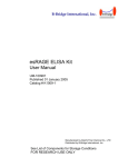
1.2.4.1
ASR
An arithmetic shift right (ASR) by n bits moves the left-hand 32 n bits of the register Rm, to the right
by n places, into the right-hand 32 n bits of the result. And it copies the original bit[31] of the register
into the left-hand n bits of the result. See Figure 1-1 on page 17.
You can use the ASR #n operation to divide the value in the register Rm by 2n, with the result being
rounded towards negative-infinity.
When the instruction is ASRS or when ASR #n is used in Operand2 with the instructions MOVS,
MVNS, ANDS, ORRS, ORNS, EORS, BICS, TEQ or TST, the carry flag is updated to the last bit shifted
out, bit[n-1], of the register Rm.
Note:
■ If n is 32 or more, then all the bits in the result are set to the value of bit[31] of Rm.
■ If n is 32 or more and the carry flag is updated, it is updated to the value of bit[31] of Rm.
Figure 1-1. ASR #3
Carry
Flag
31
5 4 3 2 1 0
...
September 07, 2010
17
Texas Instruments Incorporated
Introduction
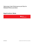
1.2.4.2
LSR
A logical shift right (LSR) by n bits moves the left-hand 32 n bits of the register Rm, to the right by
n places, into the right-hand 32 n bits of the result. And it sets the left-hand n bits of the result to
0. See Figure 1-2 on page 18.
You can use the LSR #n operation to divide the value in the register Rm by 2n, if the value is regarded
as an unsigned integer.
When the instruction is LSRS or when LSR #n is used in Operand2 with the instructions MOVS,
MVNS, ANDS, ORRS, ORNS, EORS, BICS, TEQ or TST, the carry flag is updated to the last bit shifted
out, bit[n-1], of the register Rm.
Note:
■ If n is 32 or more, then all the bits in the result are cleared to 0.
■ If n is 33 or more and the carry flag is updated, it is updated to 0.
Figure 1-2. LSR #3
0
0
Carry
Flag
0
31
5 4 3 2 1 0
...
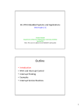
1.2.4.3
LSL
A logical shift left (LSL) by n bits moves the right-hand 32 n bits of the register Rm, to the left by n
places, into the left-hand 32 n bits of the result. And it sets the right-hand n bits of the result to 0.
See Figure 1-3 on page 19.
You can use the LSL #n operation to multiply the value in the register Rm by 2n, if the value is
regarded as an unsigned integer or a two’s complement signed integer. Overflow can occur without
warning.
When the instruction is LSLS or when LSL #n, with non-zero n, is used in Operand2 with the
instructions MOVS, MVNS, ANDS, ORRS, ORNS, EORS, BICS, TEQ or TST, the carry flag is updated to
the last bit shifted out, bit[32 n], of the register Rm. These instructions do not affect the carry flag
when used with LSL #0.
Note:
■ If n is 32 or more, then all the bits in the result are cleared to 0.
■ If n is 33 or more and the carry flag is updated, it is updated to 0.
18
September 07, 2010
Texas Instruments Incorporated
Cortex-M3 Instruction Set
Figure 1-3. LSL #3
0
31
0
5 4 3 2 1 0
Carry
Flag
1.2.4.4
0
...
ROR
A rotate right (ROR) by n bits moves the left-hand 32 n bits of the register Rm, to the right by n
places, into the right-hand 32 n bits of the result. And it moves the right-hand n bits of the register
into the left-hand n bits of the result. See Figure 1-4 on page 19.
When the instruction is RORS or when ROR #n is used in Operand2 with the instructions MOVS,
MVNS, ANDS, ORRS, ORNS, EORS, BICS, TEQ or TST, the carry flag is updated to the last bit rotation,
bit[n-1], of the register Rm.
Note:
■ If n is 32, then the value of the result is the same as the value in Rm, and if the carry flag
is updated, it is updated to bit[31] of Rm.
■ ROR with shift length, n, more than 32 is the same as ROR with shift length n 32.
Figure 1-4. ROR #3
Carry
Flag
31
5 4 3 2
1 0
...
1.2.4.5
RRX
A rotate right with extend (RRX) moves the bits of the register Rm to the right by one bit. And it copies
the carry flag into bit[31] of the result. See Figure 1-5 on page 19.
When the instruction is RRXS or when RRX is used in Operand2 with the instructions MOVS, MVNS,
ANDS, ORRS, ORNS, EORS, BICS, TEQ or TST, the carry flag is updated to bit[0] of the register Rm.
Figure 1-5. RRX
Carry
Flag
31 30
1 0
...
...
September 07, 2010
19
Texas Instruments Incorporated
Introduction
1.2.5
Address Alignment
An aligned access is an operation where a word-aligned address is used for a word, dual word, or
multiple word access, or where a halfword-aligned address is used for a halfword access. Byte
accesses are always aligned.
The Cortex-M3 processor supports unaligned access only for the following instructions:
■
■
■
■
■
LDR, LDRT
LDRH, LDRHT
LDRSH, LDRSHT
STR, STRT
STRH, STRHT
All other load and store instructions generate a usage fault exception if they perform an unaligned
access, and therefore their accesses must be address aligned. For more information about usage
faults, see "Fault Handling" in the Stellaris® Data Sheet.
Unaligned accesses are usually slower than aligned accesses. In addition, some memory regions
might not support unaligned accesses. Therefore, ARM recommends that programmers ensure that
accesses are aligned. To avoid accidental generation of unaligned accesses, use the UNALIGNED
bit in the Configuration and Control (CFGCTRL) register to trap all unaligned accesses (see
CFGCTRL in the Stellaris® Data Sheet.
1.2.6
PC-Relative Expressions
A PC-relative expression or label is a symbol that represents the address of an instruction or literal
data. It is represented in the instruction as the PC value plus or minus a numeric offset. The assembler
calculates the required offset from the label and the address of the current instruction. If the offset
is too big, the assembler produces an error.
Note:
■ For B, BL, CBNZ, and CBZ instructions, the value of the PC is the address of the current
instruction plus 4 bytes.
■ For all other instructions that use labels, the value of the PC is the address of the current
instruction plus 4 bytes, with bit[1] of the result cleared to 0 to make it word-aligned.
■ Your assembler might permit other syntaxes for PC-relative expressions, such as a label
plus or minus a number, or an expression of the form [PC, #number].
1.2.7
Conditional Execution
Most data processing instructions can optionally update the condition flags in the Application
Program Status Register (APSR) register according to the result of the operation (see APSR in
the Stellaris® Data Sheet). Some instructions update all flags, and some only update a subset. If a
flag is not updated, the original value is preserved. See the instruction descriptions for the flags they
affect.
You can execute an instruction conditionally, based on the condition flags set in another instruction,
either immediately after the instruction that updated the flags, or after any number of intervening
instructions that have not updated the flags.
Conditional execution is available by using conditional branches or by adding condition code suffixes
to instructions. See Table 1-2 on page 22 for a list of the suffixes to add to instructions to make
them conditional instructions. The condition code suffix enables the processor to test a condition
based on the flags. If the condition test of a conditional instruction fails, the instruction:
20
September 07, 2010
Texas Instruments Incorporated
Cortex-M3 Instruction Set
■ Does not execute
■ Does not write any value to its destination register
■ Does not affect any of the flags
■ Does not generate any exception
Conditional instructions, except for conditional branches, must be inside an If-Then instruction block.
See “IT” on page 77 for more information and restrictions when using the IT instruction. Depending
on the vendor, the assembler might automatically insert an IT instruction if you have conditional
instructions outside the IT block. See “IT” on page 77 for more on the IT block.
Use the CBZ and CBNZ instructions to compare the value of a register against zero and branch on
the result.
1.2.7.1
Condition Flags
The Application Program Status Register (APSR) contains the following condition flags:
■ N. Set to 1 when the result of the operation was negative; cleared to 0 otherwise.
■ Z. Set to 1 when the result of the operation was zero; cleared to 0 otherwise.
■ C. Set to 1 when the operation resulted in a carry; cleared to 0 otherwise.
■ V. Set to 1 when the operation caused overflow; cleared to 0 otherwise.
For more information about APSR, see the Stellaris® Data Sheet.
A carry occurs:
■ If the result of an addition is greater than or equal to 232
■ If the result of a subtraction is positive or zero
■ As the result of an inline barrel shifter operation in a move or logical instruction
Overflow occurs if the result of an add, subtract, or compare is greater than or equal to 231, or less
than –231.
Note:
1.2.7.2
Most instructions update the status flags only if the S suffix is specified. See the instruction
descriptions for more information.
Condition Code Suffixes
The instructions that can be conditional have an optional condition code, shown in syntax descriptions
as {cond}. Conditional execution requires a preceding IT instruction. An instruction with a condition
code is only executed if the condition code flags in APSR meet the specified condition. Table
1-2 on page 22 shows the condition codes to use.
You can use conditional execution with the IT instruction to reduce the number of branch instructions
in code.
Table 1-2 on page 22 also shows the relationship between condition code suffixes and the N, Z, C,
and V flags.
September 07, 2010
21
Texas Instruments Incorporated
Introduction
Table 1-2. Condition Code Suffixes
Suffix
Flags
Meaning
EQ
Z=1
Equal
NE
Z=0
Not equal
CS or HS
C=1
Higher or same, unsigned ≥
CC or LO
C=0
Lower, unsigned <
MI
N=1
Negative
PL
N=0
Positive or zero
VS
V=1
Overflow
VC
V=0
No overflow
HI
C = 1 and Z = 0
Higher, unsigned >
LS
C = 0 or Z = 1
Lower or same, unsigned ≤
GE
N=V
Greater than or equal, signed ≥
LT
N != V
Less than, signed <
GT
Z = 0 and N = V
Greater than, signed >
LE
Z = 1 and N != V
Less than or equal, signed ≤
AL
Can have any value
Always. This is the default when no suffix is specified.
Example 1-1, “Absolute Value” on page 22 shows the use of a conditional instruction to find the
absolute value of a number. R0 = ABS(R1).
Example 1-1. Absolute Value
MOVS
IT
RSBMI
R0, R1
MI
R0, R1, #0
; R0 = R1, setting flags.
; IT instruction for the negative condition.
; If negative, R0 = -R1.
Example 1-2, “Compare and Update Value” on page 22 shows the use of conditional instructions
to update the value of R4 if the signed value R0 is greater than R1 and R2 is greater than R3.
Example 1-2. Compare and Update Value
CMP
ITT
CMPGT
MOVGT
1.2.8
R0, R1
GT
R2, R3
R4, R5
;
;
;
;
Compare R0 and R1, setting flags
IT instruction for the two GT conditions
If 'greater than', compare R2 and R3, setting flags
If still 'greater than', do R4 = R5
Instruction Width Selection
There are many instructions that can generate either a 16-bit encoding or a 32-bit encoding depending
on the operands and destination register specified. For some of these instructions, you can force a
specific instruction size by using an instruction width suffix. The .W suffix forces a 32-bit instruction
encoding. The .N suffix forces a 16-bit instruction encoding.
If you specify an instruction width suffix and the assembler cannot generate an instruction encoding
of the requested width, it generates an error.
Note:
In some cases it might be necessary to specify the .W suffix, for example if the operand is
the label of an instruction or literal data, as in the case of branch instructions. This is because
the assembler might not automatically generate the right size encoding.
22
September 07, 2010
Texas Instruments Incorporated
Cortex-M3 Instruction Set
To use an instruction width suffix, place it immediately after the instruction mnemonic and condition
code, if any. Example 1-3, “Instruction Width Selection” on page 23 shows instructions with the
instruction width suffix.
Example 1-3. Instruction Width Selection
BCS.W
label
; creates a 32-bit instruction even for a short branch
ADDS.W R0, R0, R1 ; creates a 32-bit instruction even though the same
; operation can be done by a 16-bit instruction
September 07, 2010
23
Texas Instruments Incorporated
Memory Access Instructions
2
Memory Access Instructions
Table 2-1 on page 24 shows the memory access instructions:
Table 2-1. Memory Access Instructions
Mnemonic
Brief Description
ADR
Load PC-relative address
25
CLREX
Clear exclusive
41
LDM{mode}
Load multiple registers
35
LDR{type}
Load register using immediate offset
26
LDR{type}
Load register using register offset
29
LDR{type}T
Load register with unprivileged access
31
LDR{type}
Load register using PC-relative address
33
LDRD
Load register using PC-relative address (two words)
33
LDREX{type}
Load register exclusive
39
POP
Pop registers from stack
37
PUSH
Push registers onto stack
37
STM{mode}
Store multiple registers
35
STR{type}
Store register using immediate offset
26
STR{type}
Store register using register offset
35
STR{type}T
Store register with unprivileged access
31
STREX{type}
Store register exclusive
39
24
See Page
September 07, 2010
Texas Instruments Incorporated
Cortex-M3 Instruction Set
2.1
ADR
Load PC-relative address.
2.1.1
Syntax
ADR{cond} Rd, label
where:
cond
Is an optional condition code. See Table 1-2 on page 22.
Rd
Is the destination register.
label
Is a PC-relative expression. See “PC-Relative Expressions” on page 20.
2.1.2
Operation
ADR determines the address by adding an immediate value to the PC, and writes the result to the
destination register.
ADR produces position-independent code, because the address is PC-relative.
If you use ADR to generate a target address for a BX or BLX instruction, you must ensure that bit[0]
of the address you generate is set to 1 for correct execution.
Values of label must be within the range of −4095 to +4095 from the address in the PC.
Note:
2.1.3
You might have to use the .W suffix to get the maximum offset range or to generate
addresses that are not word-aligned. See “Instruction Width Selection” on page 22.
Restrictions
Rd must not be SP and must not be PC.
2.1.4
Condition Flags
This instruction does not change the flags.
2.1.5
Examples
ADR
R1, TextMessage
; Write address value of a location labeled as
; TextMessage to R1.
September 07, 2010
25
Texas Instruments Incorporated
Memory Access Instructions
2.2
LDR and STR (Immediate Offset)
Load and Store with immediate offset, pre-indexed immediate offset, or post-indexed immediate
offset.
2.2.1
Syntax
op{type}{cond} Rt, [Rn {, #offset}]
; immediate offset
op{type}{cond} Rt, [Rn, #offset]!
; pre-indexed
op{type}{cond} Rt, [Rn], #offset
; post-indexed
opD{cond} Rt, Rt2, [Rn {, #offset}]
; immediate offset, two words
opD{cond} Rt, Rt2, [Rn, #offset]!
; pre-indexed, two words
opD{cond} Rt, Rt2, [Rn], #offset
; post-indexed, two words
where:
op
Is one of:
LDR
Load Register.
STR
Store Register.
type
Is one of:
B
Unsigned byte, zero extend to 32 bits on loads.
SB
Signed byte, sign extend to 32 bits (LDR only).
H
Unsigned halfword, zero extend to 32 bits on loads.
SH
Signed halfword, sign extend to 32 bits (LDR only).
Omit, for word.
cond
Is an optional condition code. See Table 1-2 on page 22.
Rt
Is the register to load or store.
26
September 07, 2010
Texas Instruments Incorporated
Cortex-M3 Instruction Set
Rn
Is the register on which the memory address is based.
offset
Is an offset from Rn. If offset is omitted, the address is the contents of Rn.
Rt2
Is the additional register to load or store for two-word operations.
2.2.2
Operation
LDR instructions load one or two registers with a value from memory.
STR instructions store one or two register values to memory.
Load and store instructions with immediate offset can use the following addressing modes:
Offset addressing
The offset value is added to or subtracted from the address obtained from the register Rn. The
result is used as the address for the memory access. The register Rn is unaltered. The assembly
language syntax for this mode is:
[Rn, #offset]
Pre-indexed addressing
The offset value is added to or subtracted from the address obtained from the register Rn. The
result is used as the address for the memory access and written back into the register Rn. The
assembly language syntax for this mode is:
[Rn, #offset]!
Post-indexed addressing
The address obtained from the register Rn is used as the address for the memory access. The
offset value is added to or subtracted from the address, and written back into the register Rn.
The assembly language syntax for this mode is:
[Rn], #offset
The value to load or store can be a byte, halfword, word, or two words. Bytes and halfwords can
either be signed or unsigned. See “Address Alignment” on page 20.
Table 2-2 on page 27 shows the ranges of offset for immediate, pre-indexed and post-indexed
forms.
Table 2-2. Offset Ranges
Instruction Type
2.2.3
Immediate Offset
Pre-Indexed
Post-Indexed
Word, halfword, signed halfword, −255 to 4095
byte, or signed byte
−255 to 255
−255 to 255
Two words
Multiple of 4 in the range
−1020 to 1020
Multiple of 4 in the range
−1020 to 1020
Multiple of 4 in the range
−1020 to 1020
Restrictions
For load instructions:
■ Rt can be SP or PC for word loads only.
September 07, 2010
27
Texas Instruments Incorporated
Memory Access Instructions
■ Rt must be different from Rt2 for two-word loads.
■ Rn must be different from Rt and Rt2 in the pre-indexed or post-indexed forms.
When Rt is PC in a word load instruction:
■ Bit[0] of the loaded value must be 1 for correct execution.
■ A branch occurs to the address created by changing bit[0] of the loaded value to 0.
■ If the instruction is conditional, it must be the last instruction in the IT block.
For store instructions:
■ Rt can be SP for word stores only.
■ Rt must not be PC.
■ Rn must not be PC.
■ Rn must be different from Rt and Rt2 in the pre-indexed or post-indexed forms.
2.2.4
Condition Flags
These instructions do not change the flags.
2.2.5
Examples
LDR
LDRNE
R8, [R10]
R2, [R5, #960]!
STR
R2, [R9,#const-struc]
STRH
R3, [R4], #4
LDRD
R8, R9, [R3, #0x20]
STRD
R0, R1, [R8], #-16
;
;
;
;
;
;
;
;
;
;
;
;
;
;
Loads R8 from the address in R10.
Loads (conditionally) R2 from a word
960 bytes above the address in R5, and
increments R5 by 960.
const-struc is an expression evaluating
to a constant in the range 0-4095.
Store R3 as halfword data into address in
R4, then increment R4 by 4.
Load R8 from a word 32 bytes above the
address in R3, and load R9 from a word 36
bytes above the address in R3.
Store R0 to address in R8, and store R1 to
a word 4 bytes above the address in R8,
and then decrement R8 by 16.
28
September 07, 2010
Texas Instruments Incorporated
Cortex-M3 Instruction Set
2.3
LDR and STR (Register Offset)
Load and Store with register offset.
2.3.1
Syntax
op{type}{cond} Rt, [Rn, Rm {, LSL #n}]
where:
op
Is one of:
LDR
Load Register.
STR
Store Register.
type
Is one of:
B
Unsigned byte, zero extend to 32 bits on loads.
SB
Signed byte, sign extend to 32 bits (LDR only).
H
Unsigned halfword, zero extend to 32 bits on loads.
SH
Signed halfword, sign extend to 32 bits (LDR only).
Omit, for word.
cond
Is an optional condition code. See Table 1-2 on page 22.
Rt
Is the register to load or store.
Rn
Is the register on which the memory address is based.
Rm
Is a register containing a value to be used as the offset.
LSL #n
Is an optional shift, with n in the range 0 to 3.
2.3.2
Operation
LDR instructions load a register with a value from memory.
September 07, 2010
29
Texas Instruments Incorporated
Memory Access Instructions
STR instructions store a register value into memory.
The memory address to load from or store to is at an offset from the register Rn. The offset is
specified by the register Rm and can be shifted left by up to 3 bits using LSL.
The value to load or store can be a byte, halfword, or word. For load instructions, bytes and halfwords
can either be signed or unsigned. See “Address Alignment” on page 20.
2.3.3
Restrictions
In these instructions:
■ Rn must not be PC.
■ Rm must not be SP and must not be PC.
■ Rt can be SP only for word loads and word stores.
■ Rt can be PC only for word loads.
When Rt is PC in a word load instruction:
■ Bit[0] of the loaded value must be 1 for correct execution, and a branch occurs to this
halfword-aligned address.
■ If the instruction is conditional, it must be the last instruction in the IT block.
2.3.4
Condition Flags
These instructions do not change the flags.
2.3.5
Examples
STR
LDRSB
STR
R0, [R5, R1]
;
;
R0, [R5, R1, LSL #1] ;
;
;
R0, [R1, R2, LSL #2] ;
;
Store value of R0 into an address equal to
sum of R5 and R1.
Read byte value from an address equal to
sum of R5 and two times R1, sign extend it
to a word value and put it in R0.
Store R0 to an address equal to sum of R1
and four times R2.
30
September 07, 2010
Texas Instruments Incorporated
Cortex-M3 Instruction Set
2.4
LDR and STR (Unprivileged Access)
Load and Store with unprivileged access.
2.4.1
Syntax
op{type}T{cond} Rt, [Rn {, #offset}]
; immediate offset
where:
op
Is one of:
LDR
Load Register.
STR
Store Register.
type
Is one of:
B
Unsigned byte, zero extend to 32 bits on loads.
SB
Signed byte, sign extend to 32 bits (LDR only).
H
Unsigned halfword, zero extend to 32 bits on loads.
SH
Signed halfword, sign extend to 32 bits (LDR only).
Omit, for word.
cond
Is an optional condition code. See Table 1-2 on page 22.
Rt
Is the register to load or store.
Rn
Is the register on which the memory address is based.
offset
Is an offset from Rn and can be 0 to 255. If offset is omitted, the address is the value in Rn.
2.4.2
Operation
These load and store instructions perform the same function as the memory access instructions
with immediate offset (see “LDR and STR (Immediate Offset)” on page 26). The difference is that
these instructions have only unprivileged access even when used in privileged software.
September 07, 2010
31
Texas Instruments Incorporated
Memory Access Instructions
When used in unprivileged software, these instructions behave in exactly the same way as normal
memory access instructions with immediate offset.
2.4.3
Restrictions
In these instructions:
■ Rn must not be PC.
■ Rt must not be SP and must not be PC.
2.4.4
Condition Flags
These instructions do not change the flags.
2.4.5
Examples
STRBTEQ
R4, [R7]
LDRHT
R2, [R2, #8]
;
;
;
;
Conditionally store least significant byte in
R4 to an address in R7, with unprivileged access.
Load halfword value from an address equal to
sum of R2 and 8 into R2, with unprivileged access.
32
September 07, 2010
Texas Instruments Incorporated
Cortex-M3 Instruction Set
2.5
LDR (PC-Relative)
Load register from memory.
2.5.1
Syntax
LDR{type}{cond} Rt, label
LDRD{cond} Rt, Rt2, label
; Load two words
where:
type
Is one of:
B
Unsigned byte, zero extend to 32 bits.
SB
Signed byte, sign extend to 32 bits.
H
Unsigned halfword, zero extend to 32 bits.
SH
Signed halfword, sign extend to 32 bits.
Omit, for word.
cond
Is an optional condition code. See Table 1-2 on page 22.
Rt
Is the register to load or store.
Rt2
Is the second register to load or store.
label
Is a PC-relative expression. See “PC-Relative Expressions” on page 20.
2.5.2
Operation
LDR loads a register with a value from a PC-relative memory address. The memory address is
specified by a label or by an offset from the PC.
The value to load or store can be a byte, halfword, or word. For load instructions, bytes and halfwords
can either be signed or unsigned. See “Address Alignment” on page 20.
label must be within a limited range of the current instruction. Table 2-3 on page 34 shows the
possible offsets between label and the PC.
September 07, 2010
33
Texas Instruments Incorporated
Memory Access Instructions
Table 2-3. Offset Ranges
a
Instruction Type
Offset Range
Word, halfword, signed halfword, byte, signed byte
−4095 to 4095
Two words
−1020 to 1020
a. You might have to use the .W suffix to get the maximum offset range. See “Instruction Width Selection” on page 22.
2.5.3
Restrictions
In these instructions:
■ Rt can be SP or PC only for word loads.
■ Rt2 must not be SP and must not be PC.
■ Rt must be different from Rt2.
When Rt is PC in a word load instruction:
■ Bit[0] of the loaded value must be 1 for correct execution, and a branch occurs to this
halfword-aligned address.
■ If the instruction is conditional, it must be the last instruction in the IT block.
2.5.4
Condition Flags
These instructions do not change the flags.
2.5.5
Examples
LDR
R0, LookUpTable
LDRSB
R7, localdata
;
;
;
;
;
Load R0 with a word of data from an address
labeled as LookUpTable.
Load a byte value from an address labeled
as localdata, sign extend it to a word
value, and put it in R7.
34
September 07, 2010
Texas Instruments Incorporated
Cortex-M3 Instruction Set
2.6
LDM and STM
Load and Store Multiple registers.
2.6.1
Syntax
op{addr_mode}{cond} Rn{!}, reglist
where:
op
Is one of:
LDM
Load Multiple registers.
STM
Store Multiple registers.
addr_mode
Is any one of the following:
IA
Increment address After each access. This is the default.
DB
Decrement address Before each access.
cond
Is an optional condition code. See Table 1-2 on page 22.
Rn
Is the register on which the memory addresses are based.
!
Is an optional writeback suffix. If ! is present then the final address, that is loaded from or stored
to, is written back into Rn.
reglist
Is a list of one or more registers to be loaded or stored, enclosed in braces. It can contain register
ranges. It must be comma separated if it contains more than one register or register range. See
“Examples” on page 36.
LDM and LDMFD are synonyms for LDMIA. LDMFD refers to its use for popping data from Full
Descending stacks.
LDMEA is a synonym for LDMDB, and refers to its use for popping data from Empty Ascending stacks.
STM and STMEA are synonyms for STMIA. STMEA refers to its use for pushing data onto Empty
Ascending stacks.
STMFD is s synonym for STMDB, and refers to its use for pushing data onto Full Descending stacks
September 07, 2010
35
Texas Instruments Incorporated
Memory Access Instructions
2.6.2
Operation
LDM instructions load the registers in reglist with word values from memory addresses based on
Rn.
STM instructions store the word values in the registers in reglist to memory addresses based on
Rn.
For LDM, LDMIA, LDMFD, STM, STMIA, and STMEA, the memory addresses used for the accesses
are at 4-byte intervals ranging from Rn to Rn + 4 * (n-1), where n is the number of registers in
reglist. The accesses happen in order of increasing register numbers, with the lowest numbered
register using the lowest memory address and the highest number register using the highest memory
address. If the writeback suffix is specified, the value of Rn + 4 * (n-1) is written back to Rn.
For LDMDB, LDMEA, STMDB, and STMFD, the memory addresses used for the accesses are at 4-byte
intervals ranging from Rn to Rn - 4 * (n-1), where n is the number of registers in reglist. The
accesses happen in order of decreasing register numbers, with the highest numbered register using
the highest memory address and the lowest number register using the lowest memory address. If
the writeback suffix is specified, the value of Rn - 4 * (n-1) is written back to Rn.
The PUSH and POP instructions can be expressed in this form. See “PUSH and POP” on page 37
for details.
2.6.3
Restrictions
In these instructions:
■ Rn must not be PC.
■ reglist must not contain SP.
■ In any STM instruction, reglist must not contain PC.
■ In any LDM instruction, reglist must not contain PC if it contains LR.
■ reglist must not contain Rn if you specify the writeback suffix.
When PC is in reglist in an LDM instruction:
■ Bit[0] of the value loaded to the PC must be 1 for correct execution, and a branch occurs to this
halfword-aligned address.
■ If the instruction is conditional, it must be the last instruction in the IT block.
2.6.4
Condition Flags
These instructions do not change the flags.
2.6.5
Examples
LDM
STMDB
2.6.6
R8,{R0,R2,R9}
; LDMIA is a synonym for LDM.
R1!,{R3-R6,R11,R12}
Incorrect Examples
STM
LDM
R5!,{R5,R4,R9} ; Value stored for R5 is unpredictable.
R2, {}
; There must be at least one register in the list.
36
September 07, 2010
Texas Instruments Incorporated
Cortex-M3 Instruction Set
2.7
PUSH and POP
Push registers on and pop registers off a full-descending stack.
2.7.1
Syntax
PUSH{cond} reglist
POP{cond} reglist
where:
cond
Is an optional condition code. See Table 1-2 on page 22.
reglist
Is a non-empty list of registers, enclosed in braces. It can contain register ranges. It must be
comma separated if it contains more than one register or register range.
PUSH and POP are synonyms for STMDB and LDM (or LDMIA) with the memory addresses for the
access based on SP, and with the final address for the access written back to the SP. PUSH and
POP are the preferred mnemonics in these cases.
2.7.2
Operation
PUSH stores registers on the stack in order of decreasing register numbers, with the highest numbered
register using the highest memory address and the lowest numbered register using the lowest
memory address.
POP loads registers from the stack in order of increasing register numbers, with the lowest numbered
register using the lowest memory address and the highest numbered register using the highest
memory address.
See “LDM and STM” on page 35 for more information.
2.7.3
Restrictions
In these instructions:
■ reglist must not contain SP.
■ For the PUSH instruction, reglist must not contain PC.
■ For the POP instruction, reglist must not contain PC if it contains LR.
When PC is in reglist in a POP instruction:
■ Bit[0] of the value loaded to the PC must be 1 for correct execution, and a branch occurs to this
halfword-aligned address.
■ If the instruction is conditional, it must be the last instruction in the IT block.
2.7.4
Condition Flags
These instructions do not change the flags.
September 07, 2010
37
Texas Instruments Incorporated
Memory Access Instructions
2.7.5
Examples
PUSH
PUSH
POP
{R0,R4-R7}
{R2,LR}
{R0,R10,PC}
38
September 07, 2010
Texas Instruments Incorporated
Cortex-M3 Instruction Set
2.8
LDREX and STREX
Load and Store Register Exclusive.
2.8.1
Syntax
LDREX{cond} Rt, [Rn {, #offset}]
STREX{cond} Rd, Rt, [Rn {, #offset}]
LDREXB{cond} Rt, [Rn]
STREXB{cond} Rd, Rt, [Rn]
LDREXH{cond} Rt, [Rn]
STREXH{cond} Rd, Rt, [Rn]
where:
cond
Is an optional condition code. See Table 1-2 on page 22.
Rd
Is the destination register for the returned status.
Rt
Is the register to load or store.
Rn
Is the register on which the memory address is based.
offset
Is an optional offset applied to the value in Rn. If offset is omitted, the address is the value
in Rn.
2.8.2
Operation
LDREX, LDREXB, and LDREXH load a word, byte, and halfword respectively from a memory address.
STREX, STREXB, and STREXH attempt to store a word, byte, and halfword respectively to a memory
address. The address used in any Store-Exclusive instruction must be the same as the address in
the most recently executed Load-exclusive instruction. The value stored by the Store-Exclusive
instruction must also have the same data size as the value loaded by the preceding Load-exclusive
instruction. This means software must always use a Load-exclusive instruction and a matching
Store-Exclusive instruction to perform a synchronization operation (see "Synchronization Primitives"
in the Stellaris® Data Sheet).
If a Store-Exclusive instruction performs the store, it writes 0 to its destination register. If it does not
perform the store, it writes 1 to its destination register. If the Store-Exclusive instruction writes 0 to
the destination register, it is guaranteed that no other process in the system has accessed the
memory location between the Load-exclusive and Store-Exclusive instructions.
For reasons of performance, keep the number of instructions between corresponding Load-Exclusive
and Store-Exclusive instruction to a minimum.
September 07, 2010
39
Texas Instruments Incorporated
Memory Access Instructions
Important: The result of executing a Store-Exclusive instruction to an address that is different from
that used in the preceding Load-Exclusive instruction is unpredictable.
2.8.3
Restrictions
In these instructions:
■ Do not use PC.
■ Do not use SP for Rd and Rt.
■ For STREX, Rd must be different from both Rt and Rn.
■ The value of offset must be a multiple of four in the range 0-1020.
2.8.4
Condition Flags
These instructions do not change the flags.
2.8.5
Examples
MOV
try
LDREX
CMP
ITT
STREXEQ
CMPEQ
BNE
....
R1, #0x1
; Initialize the ‘lock taken’ value.
R0,
R0,
EQ
R0,
R0,
try
;
;
;
;
;
;
;
[LockAddr]
#0
R1, [LockAddr]
#0
Load the lock value.
Is the lock free?
IT instruction for STREXEQ and CMPEQ.
Try and claim the lock.
Did this succeed?
No – try again.
Yes – we have the lock.
40
September 07, 2010
Texas Instruments Incorporated
Cortex-M3 Instruction Set
2.9
CLREX
Clear Exclusive.
2.9.1
Syntax
CLREX{cond}
where:
cond
Is an optional condition code. See Table 1-2 on page 22.
2.9.2
Operation
Use CLREX to make the next STREX, STREXB, or STREXH instruction write 1 to its destination register
and fail to perform the store. It is useful in exception handler code to force the failure of the store
exclusive if the exception occurs between a load exclusive instruction and the matching store
exclusive instruction in a synchronization operation (see "Synchronization Primitives" in the Stellaris®
Data Sheet).
2.9.3
Condition Flags
These instructions do not change the flags.
2.9.4
Examples
CLREX
September 07, 2010
41
Texas Instruments Incorporated
General Data Processing Instructions
3
General Data Processing Instructions
Table 3-1 on page 42 shows the data processing instructions:
Table 3-1. General Data Processing Instructions
Mnemonic
Brief Description
ADC
Add with carry
43
ADD
Add
43
ADDW
Add
43
AND
Logical AND
46
ASR
Arithmetic shift right
48
BIC
Bit clear
46
CLZ
Count leading zeros
50
CMN
Compare negative
51
CMP
Compare
51
EOR
Exclusive OR
46
LSL
Logical shift left
48
LSR
Logical shift right
48
MOV
Move
52
MOVT
Move top
54
MOVW
Move 16-bit constant
52
MVN
Move NOT
52
ORN
Logical OR NOT
46
ORR
Logical OR
46
RBIT
Reverse bits
55
REV
Reverse byte order in a word
55
REV16
Reverse byte order in each halfword
55
REVSH
Reverse byte order in bottom halfword and sign extend
55
ROR
Rotate right
48
RRX
Rotate right with extend
48
RSB
Reverse subtract
43
SBC
Subtract with carry
43
SUB
Subtract
43
SUBW
Subtract
43
TEQ
Test equivalence
57
TST
Test
57
42
See Page
September 07, 2010
Texas Instruments Incorporated
Cortex-M3 Instruction Set
3.1
ADD, ADC, SUB, SBC, and RSB
Add, Add with carry, Subtract, Subtract with carry, and Reverse Subtract.
3.1.1
Syntax
op{S}{cond} {Rd,} Rn, Operand2
op{cond} {Rd,} Rn, #imm12
; ADD and SUB only
where:
op
Is one of:
ADD
Add.
ADC
Add with Carry.
SUB
Subtract.
SBC
Subtract with Carry.
RSB
Reverse Subtract.
S
Is an optional suffix. If S is specified, the condition code flags are updated on the result of the
operation. See “Conditional Execution” on page 20.
cond
Is an optional condition code. See Table 1-2 on page 22.
Rd
Is the destination register. If Rd is omitted, the destination register is Rn.
Rn
Is the register holding the first operand.
Operand2
Is a flexible second operand. See “Flexible Second Operand” on page 15 for details of the
options.
imm12
Is any value in the range 0-4095.
3.1.2
Operation
The ADD instruction adds the value of Operand2 or imm12 to the value in Rn.
The ADC instruction adds the values in Rn and Operand2, together with the carry flag.
September 07, 2010
43
Texas Instruments Incorporated
General Data Processing Instructions
The SUB instruction subtracts the value of Operand2 or imm12 from the value in Rn.
The SBC instruction subtracts the value of Operand2 from the value in Rn. If the carry flag is clear,
the result is reduced by one.
The RSB instruction subtracts the value in Rn from the value of Operand2. This is useful because
of the wide range of options for Operand2.
Use ADC and SBC to synthesize multiword arithmetic. See “Multiword Arithmetic
Examples” on page 45.
See also 25.
Note:
3.1.3
ADDW is equivalent to the ADD syntax that uses the imm12 operand. SUBW is equivalent to
the SUB syntax that uses the imm12 operand.
Restrictions
In these instructions:
■ Operand2 must not be SP and must not be PC.
■ Rd can be SP only in ADD and SUB, and only with the additional restrictions:
– Rn must also be SP.
– any shift in Operand2 must be limited to a maximum of 3 bits using LSL.
■ Rn can be SP only in ADD and SUB.
■ Rd can be PC only in the ADD{cond} PC, PC, Rm instruction where:
– You must not specify the S suffix.
– Rm must not be PC and must not be SP.
– If the instruction is conditional, it must be the last instruction in the IT block.
■ With the exception of the ADD{cond} PC, PC, Rm instruction, Rn can be PC only in ADD and
SUB, and only with the additional restrictions:
– You must not specify the S suffix.
– The second operand must be a constant in the range 0 to 4095.
Note:
– When using the PC for an addition or a subtraction, bits[1:0] of the PC are rounded
to b00 before performing the calculation, making the base address for the calculation
word-aligned.
– If you want to generate the address of an instruction, you have to adjust the constant
based on the value of the PC. ARM recommends that you use the ADR instruction
instead of ADD or SUB with Rn equal to the PC, because your assembler automatically
calculates the correct constant for the ADR instruction.
When Rd is PC in the ADD{cond} PC, PC, Rm instruction:
■ Bit[0] of the value written to the PC is ignored
■ A branch occurs to the address created by forcing bit[0] of that value to 0.
3.1.4
Condition Flags
If S is specified, these instructions update the N, Z, C and V flags according to the result.
44
September 07, 2010
Texas Instruments Incorporated
Cortex-M3 Instruction Set
3.1.5
Examples
ADD
SUBS
RSB
ADCHI
3.1.6
R2, R1, R3
R8, R6, #240
R4, R4, #1280
R11, R0, R3
;
;
;
;
Sets the flags on the result.
Subtracts contents of R4 from 1280.
Only executed if C flag set and Z
flag clear.
Multiword Arithmetic Examples
Example 3-1, “64-Bit Addition” on page 45 shows two instructions that add a 64-bit integer contained
in R2 and R3 to another 64-bit integer contained in R0 and R1, and place the result in R4 and R5.
Example 3-1. 64-Bit Addition
ADDS
ADC
R4, R0, R2
R5, R1, R3
; Add the least significant words.
; Add the most significant words with carry.
Multiword values do not have to use consecutive registers. Example 3-2, “96-Bit
Subtraction” on page 45 shows instructions that subtract a 96-bit integer contained in R9, R1, and
R11 from another contained in R6, R2, and R8. The example stores the result in R6, R9, and R2.
Example 3-2. 96-Bit Subtraction
SUBS
SBCS
SBC
R6, R6, R9
R9, R2, R1
R2, R8, R11
; Subtract the least significant words.
; Subtract the middle words with carry.
; Subtract the most significant words with carry.
September 07, 2010
45
Texas Instruments Incorporated
General Data Processing Instructions
3.2
AND, ORR, EOR, BIC, and ORN
Logical AND, OR, Exclusive OR, Bit Clear, and OR NOT.
3.2.1
Syntax
op{S}{cond} {Rd,} Rn, Operand2
where:
op
Is one of:
AND
Logical AND.
ORR
Logical OR, or bit set.
EOR
Logical Exclusive OR.
BIC
Logical AND NOT, or bit clear.
ORN
Logical OR NOT.
S
Is an optional suffix. If S is specified, the condition code flags are updated on the result of the
operation. See “Conditional Execution” on page 20.
cond
Is an optional condition code. See Table 1-2 on page 22.
Rd
Is the destination register.
Rn
Is the register holding the first operand.
Operand2
Is a flexible second operand. See “Flexible Second Operand” on page 15 for details of the
options.
3.2.2
Operation
The AND, EOR, and ORR instructions perform bitwise AND, Exclusive OR, and OR operations on the
values in Rn and Operand2.
The BIC instruction performs an AND operation on the bits in Rn with the complements of the
corresponding bits in the value of Operand2.
The ORN instruction performs an OR operation on the bits in Rn with the complements of the
corresponding bits in the value of Operand2.
46
September 07, 2010
Texas Instruments Incorporated
Cortex-M3 Instruction Set
3.2.3
Restrictions
Do not use SP and do not use PC.
3.2.4
Condition Flags
If S is specified, these instructions:
■ Update the N and Z flags according to the result.
■ Can update the C flag during the calculation of Operand2. See “Flexible Second
Operand” on page 15.
■ Do not affect the V flag.
3.2.5
Examples
AND
ORREQ
ANDS
EORS
BIC
ORN
ORNS
R9,
R2,
R9,
R7,
R0,
R7,
R7,
R2, #0xFF00
R0, R5
R8, #0x19
R11, #0x18181818
R1, #0xab
R11, R14, ROR #4
R11, R14, ASR #32
September 07, 2010
47
Texas Instruments Incorporated
General Data Processing Instructions
3.3
ASR, LSL, LSR, ROR, and RRX
Arithmetic Shift Right, Logical Shift Left, Logical Shift Right, Rotate Right, and Rotate Right with
Extend.
3.3.1
Syntax
op{S}{cond} Rd, Rm, Rs
op{S}{cond} Rd, Rm, #n
RRX{S}{cond} Rd, Rm
where:
op
Is one of:
ASR
Arithmetic Shift Right.
LSL
Logical Shift Left.
LSR
Logical Shift Right.
ROR
Rotate Right.
S
Is an optional suffix. If S is specified, the condition code flags are updated on the result of the
operation. See “Conditional Execution” on page 20.
Rd
Is the destination register.
Rm
Is the register holding the value to be shifted.
Rs
Is the register holding the shift length to apply to the value in Rm. Only the least significant byte
is used and can be in the range 0 to 255.
n
Is the shift length. The range of shift length depends on the instruction:
ASR
Shift length from 1 to 32.
LSL
Shift length from 0 to 31.
LSR
Shift length from 1 to 32.
48
September 07, 2010
Texas Instruments Incorporated
Cortex-M3 Instruction Set
ROR
Shift length from 1 to 31.
Note:
3.3.2
MOV{S}{cond} Rd, Rm is the preferred syntax for LSL{S}{cond} Rd, Rm, #0.
Operation
ASR, LSL, LSR, and ROR move the bits in the register Rm to the left or right by the number of places
specified by constant n or register Rs.
RRX moves the bits in register Rm to the right by 1.
In all these instructions, the result is written to Rd, but the value in register Rm remains unchanged.
For details on what result is generated by the different instructions, see “Shift Operations” on page 17.
3.3.3
Restrictions
Do not use SP and do not use PC.
3.3.4
Condition Flags
If S is specified:
■ These instructions update the N and Z flags according to the result.
■ The C flag is updated to the last bit shifted out, except when the shift length is 0. See “Shift
Operations” on page 17.
3.3.5
Examples
ASR
LSLS
LSR
ROR
RRX
R7,
R1,
R4,
R4,
R4,
R8,
R2,
R5,
R5,
R5
#9
#3
#6
R6
;
;
;
;
;
Arithmetic shift right by 9 bits.
Logical shift left by 3 bits with flag update.
Logical shift right by 6 bits.
Rotate right by the value in the bottom byte of R6.
Rotate right with extend.
September 07, 2010
49
Texas Instruments Incorporated
General Data Processing Instructions
3.4
CLZ
Count Leading Zeros.
3.4.1
Syntax
CLZ{cond} Rd, Rm
where:
cond
Is an optional condition code. See Table 1-2 on page 22.
Rd
Is the destination register.
Rm
Is the operand register.
3.4.2
Operation
The CLZ instruction counts the number of leading zeros in the value in Rm and returns the result in
Rd. The result value is 32 if no bits are set in the source register, and zero if bit[31] is set.
3.4.3
Restrictions
Do not use SP and do not use PC.
3.4.4
Condition Flags
This instruction does not change the flags.
3.4.5
Examples
CLZ
CLZNE
R4,R9
R2,R3
50
September 07, 2010
Texas Instruments Incorporated
Cortex-M3 Instruction Set
3.5
CMP and CMN
Compare and Compare Negative.
3.5.1
Syntax
CMP{cond} Rn, Operand2
CMN{cond} Rn, Operand2
where:
cond
Is an optional condition code. See Table 1-2 on page 22.
Rn
Is the register holding the first operand.
Operand2
Is a flexible second operand. See “Flexible Second Operand” on page 15 for details of the
options.
3.5.2
Operation
These instructions compare the value in a register with Operand2. They update the condition flags
on the result, but do not write the result to a register.
The CMP instruction subtracts the value of Operand2 from the value in Rn. This is the same as a
SUBS instruction, except that the result is discarded.
The CMN instruction adds the value of Operand2 to the value in Rn. This is the same as an ADDS
instruction, except that the result is discarded.
3.5.3
Restrictions
In these instructions:
■ Do not use PC.
■ Operand2 must not be SP.
3.5.4
Condition Flags
These instructions update the N, Z, C and V flags according to the result.
3.5.5
Examples
CMP
CMN
CMPGT
R2, R9
R0, #6400
SP, R7, LSL #2
September 07, 2010
51
Texas Instruments Incorporated
General Data Processing Instructions
3.6
MOV and MVN
Move and Move NOT.
3.6.1
Syntax
MOV{S}{cond} Rd, Operand2
MOV{cond} Rd, #imm16
MVN{S}{cond} Rd, Operand2
where:
S
Is an optional suffix. If S is specified, the condition code flags are updated on the result of the
operation. See “Conditional Execution” on page 20.
cond
Is an optional condition code. See Table 1-2 on page 22.
Rd
Is the destination register.
Operand2
Is a flexible second operand. See “Flexible Second Operand” on page 15 for details of the
options.
imm16
Is any value in the range 0-65535.
3.6.2
Operation
The MOV instruction copies the value of Operand2 into Rd.
When Operand2 in a MOV instruction is a register with a shift other than LSL #0, the preferred
syntax is the corresponding shift instruction:
MOV Instruction
Preferred Syntax using Shift Instruction
MOV{S}{cond} Rd, Rm, ASR #n
ASR{S}{cond} Rd, Rm, #n
MOV{S}{cond} Rd, Rm, LSL #n (if n != 0)
LSL{S}{cond} Rd, Rm, #n
MOV{S}{cond} Rd, Rm, LSR #n
LSR{S}{cond} Rd, Rm, #n
MOV{S}{cond} Rd, Rm, ROR #n
ROR{S}{cond} Rd, Rm, #n
MOV{S}{cond} Rd, Rm, RRX
RRX{S}{cond} Rd, Rm
Also, the MOV instruction permits additional forms of Operand2 as synonyms for shift instructions.
See “ASR, LSL, LSR, ROR, and RRX” on page 48.
Shift Instruction
MOV Instruction Synonym
ASR{S}{cond} Rd, Rm, Rs
MOV{S}{cond} Rd, Rm, ASR Rs
LSL{S}{cond} Rd, Rm, Rs
MOV{S}{cond} Rd, Rm, LSL Rs
LSR{S}{cond} Rd, Rm, Rs
MOV{S}{cond} Rd, Rm, LSR Rs
ROR{S}{cond} Rd, Rm, Rs
MOV{S}{cond} Rd, Rm, ROR Rs
52
September 07, 2010
Texas Instruments Incorporated
Cortex-M3 Instruction Set
The MVN instruction takes the value of Operand2, performs a bitwise logical NOT operation on the
value, and places the result into Rd.
Note:
3.6.3
The MOVW instruction provides the same function as MOV, but is restricted to using the imm16
operand.
Restrictions
You can use SP and PC only in the MOV instruction, with the following restrictions:
■ The second operand must be a register without shift
■ You must not specify the S suffix.
When Rd is PC in a MOV instruction:
■ Bit[0] of the value written to the PC is ignored
■ A branch occurs to the address created by forcing bit[0] of that value to 0.
Note:
3.6.4
Though it is possible to use MOV as a branch instruction, Texas Instruments strongly
recommends the use of a BX or BLX instruction to branch for software portability to the ARM
Cortex-M3 instruction set.
Condition Flags
If S is specified, these instructions:
■ Update the N and Z flags according to the result.
■ Can update the C flag during the calculation of Operand2. See “Flexible Second
Operand” on page 15.
■ Do not affect the V flag.
3.6.5
Example
MOVS
MOV
MOVS
MOV
MOV
MVNS
R11, #0x000B
R1, #0xFA05
R10, R12
R3, #23
R8, SP
R2, #0xF
;
;
;
;
;
;
;
Write
Write
Write
Write
Write
Write
to R2
value of 0x000B to R11, flags get updated.
value of 0xFA05 to R1, flags are not updated.
value in R12 to R10, flags get updated.
value of 23 to R3.
value of stack pointer to R8.
value of 0xFFFFFFF0 (bitwise inverse of 0xF)
and update flags.
September 07, 2010
53
Texas Instruments Incorporated
General Data Processing Instructions
3.7
MOVT
Move Top.
3.7.1
Syntax
MOVT{cond} Rd, #imm16
where:
cond
Is an optional condition code. See Table 1-2 on page 22.
Rd
Is the destination register.
imm16
Is a 16-bit immediate constant.
3.7.2
Operation
MOVT writes a 16-bit immediate value, imm16, to the top halfword, Rd[31:16], of its destination
register. The write does not affect Rd[15:0].
The MOV, MOVT instruction pair enables you to generate any 32-bit constant.
3.7.3
Restrictions
Rd must not be SP and must not be PC.
3.7.4
Condition Flags
This instruction does not change the flags.
3.7.5
Examples
MOVT
R3, #0xF123 ; Write 0xF123 to upper halfword of R3, lower halfword
; and APSR are unchanged.
54
September 07, 2010
Texas Instruments Incorporated
Cortex-M3 Instruction Set
3.8
REV, REV16, REVSH, and RBIT
Reverse bytes and Reverse bits.
3.8.1
Syntax
op{cond} Rd, Rn
where:
op
Is any of:
REV
Reverse byte order in a word.
REV16
Reverse byte order in each halfword independently.
REVSH
Reverse byte order in the bottom halfword, and sign extend to 32 bits.
RBIT
Reverse the bit order in a 32-bit word.
cond
Is an optional condition code. See Table 1-2 on page 22.
Rd
Is the destination register.
Rn
Is the register holding the operand.
3.8.2
Operation
Use these instructions to change endianness of data:
REV
Converts 32-bit big-endian data into little-endian data or 32-bit little-endian data into big-endian
data.
REV16
Converts 16-bit big-endian data into little-endian data or 16-bit little-endian data into big-endian
data.
REVSH
Converts either:
■ 16-bit signed big-endian data into 32-bit signed little-endian data.
■ 16-bit signed little-endian data into 32-bit signed big-endian data.
3.8.3
Restrictions
Do not use SP and do not use PC.
September 07, 2010
55
Texas Instruments Incorporated
General Data Processing Instructions
3.8.4
Condition Flags
These instructions do not change the flags.
3.8.5
Examples
REV
REV16
REVSH
REVHS
RBIT
R3,
R0,
R0,
R3,
R7,
R7
R0
R5
R7
R8
;
;
;
;
;
Reverse
Reverse
Reverse
Reverse
Reverse
byte order of value in R7 and write it to R3.
byte order of each 16-bit halfword in R0.
Signed Halfword.
with Higher or Same condition.
bit order of value in R8 and write the result to R7.
56
September 07, 2010
Texas Instruments Incorporated
Cortex-M3 Instruction Set
3.9
TST and TEQ
Test bits and Test Equivalence.
3.9.1
Syntax
TST{cond} Rn, Operand2
TEQ{cond} Rn, Operand2
where:
cond
Is an optional condition code. See Table 1-2 on page 22.
Rn
Is the register holding the first operand.
Operand2
Is a flexible second operand. See “Flexible Second Operand” on page 15 for details of the
options.
3.9.2
Operation
These instructions test the value in a register against Operand2. They update the condition flags
based on the result, but do not write the result to a register.
The TST instruction performs a bitwise AND operation on the value in Rn and the value of Operand2.
This is the same as the ANDS instruction, except that it discards the result.
To test whether a bit of Rn is 0 or 1, use the TST instruction with an Operand2 constant that has
that bit set to 1 and all other bits cleared to 0.
The TEQ instruction performs a bitwise Exclusive OR operation on the value in Rn and the value of
Operand2. This is the same as the EORS instruction, except that it discards the result.
Use the TEQ instruction to test if two values are equal without affecting the V or C flags.
TEQ is also useful for testing the sign of a value. After the comparison, the N flag is the logical
Exclusive OR of the sign bits of the two operands.
3.9.3
Restrictions
Do not use SP and do not use PC.
3.9.4
Condition Flags
These instructions:
■ Update the N and Z flags according to the result.
■ Can update the C flag during the calculation of Operand2. See “Flexible Second
Operand” on page 15.
■ Do not affect the V flag.
September 07, 2010
57
Texas Instruments Incorporated
General Data Processing Instructions
3.9.5
Examples
TST
R0, #0x3F8
TEQEQ
R10, R9
;
;
;
;
Perform bitwise AND of R0 value to 0x3F8;
APSR is updated but result is discarded.
Conditionally test if value in R10 is equal to
value in R9; APSR is updated but result is discarded.
58
September 07, 2010
Texas Instruments Incorporated
Cortex-M3 Instruction Set
4
Multiply and Divide Instructions
Table 4-1 on page 59 shows the multiply and divide instructions:
Table 4-1. Multiply and Divide Instructions
Mnemonic
Brief Description
MLA
Multiply with accumulate, 32-bit result
60
MLS
Multiply and subtract, 32-bit result
60
MUL
Multiply, 32-bit result
60
SDIV
Signed divide
64
SMLAL
Signed multiply with accumulate (32x32+64), 64-bit result
62
SMULL
Signed multiply (32x32), 64-bit result
62
UDIV
Unsigned divide
64
UMLAL
Unsigned multiply with accumulate (32x32+64), 64-bit result
62
UMULL
Unsigned multiply (32x32), 64-bit result
62
September 07, 2010
See Page
59
Texas Instruments Incorporated
Multiply and Divide Instructions
4.1
MUL, MLA, and MLS
Multiply, Multiply with Accumulate, and Multiply with Subtract, using 32-bit operands, and producing
a 32-bit result.
4.1.1
Syntax
MUL{S}{cond} {Rd,} Rn, Rm ; Multiply
MLA{cond} Rd, Rn, Rm, Ra
; Multiply with accumulate
MLS{cond} Rd, Rn, Rm, Ra
; Multiply with subtract
where:
cond
Is an optional condition code. See Table 1-2 on page 22.
S
Is an optional suffix. If S is specified, the condition code flags are updated on the result of the
operation. See “Conditional Execution” on page 20.
Rd
Is the destination register. If Rd is omitted, the destination register is Rn.
Rn, Rm
Are registers holding the values to be multiplied.
Ra
Is a register holding the value to be added or subtracted from.
4.1.2
Operation
The MUL instruction multiplies the values from Rn and Rm, and places the least-significant 32 bits
of the result in Rd.
The MLA instruction multiplies the values from Rn and Rm, adds the value from Ra, and places the
least-significant 32 bits of the result in Rd.
The MLS instruction multiplies the values from Rn and Rm, subtracts the product from Ra, and places
the least-significant 32 bits of the result in Rd.
The results of these instructions do not depend on whether the operands are signed or unsigned.
4.1.3
Restrictions
In these instructions, do not use SP and do not use PC.
If you use the S suffix with the MUL instruction:
■ Rd, Rn, and Rm must all be in the range R0 to R7.
■ Rd must be the same as Rm.
■ You must not use the cond suffix.
60
September 07, 2010
Texas Instruments Incorporated
Cortex-M3 Instruction Set
4.1.4
Condition Flags
If S is specified, the MUL instruction:
■ Updates the N and Z flags according to the result.
■ Does not affect the C and V flags.
4.1.5
Examples
MUL
MLA
MULS
MULLT
MLS
R10, R2, R5
R10, R2, R1, R5
R0, R2, R2
R2, R3, R2
R4, R5, R6, R7
;
;
;
;
;
Multiply, R10
Multiply with
Multiply with
Conditionally
Multiply with
= R2 x R5.
accumulate, R10 =
flag update, R0 =
multiply, R2 = R3
subtract, R4 = R7
September 07, 2010
(R2 x R1) + R5.
R2 x R2.
x R2.
- (R5 x R6).
61
Texas Instruments Incorporated
Multiply and Divide Instructions
4.2
UMULL, UMLAL, SMULL, and SMLAL
Signed and Unsigned Long Multiply, with optional Accumulate, using 32-bit operands and producing
a 64-bit result.
4.2.1
Syntax
op{cond} RdLo, RdHi, Rn, Rm
where:
op
Is one of:
UMULL
Unsigned Long Multiply.
UMLAL
Unsigned Long Multiply, with Accumulate.
SMULL
Signed Long Multiply.
SMLAL
Signed Long Multiply, with Accumulate.
cond
Is an optional condition code. See Table 1-2 on page 22.
RdHi, RdLo
Are the destination registers. For UMLAL and SMLAL they also hold the accumulating value.
Rn, Rm
Are registers holding the operands.
4.2.2
Operation
The UMULL instruction interprets the values from Rn and Rm as unsigned integers. It multiplies these
integers and places the least-significant 32 bits of the result in RdLo, and the most-significant 32
bits of the result in RdHi.
The UMLAL instruction interprets the values from Rn and Rm as unsigned integers. It multiplies these
integers, adds the 64-bit result to the 64-bit unsigned integer contained in RdHi and RdLo, and
writes the result back to RdHi and RdLo.
The SMULL instruction interprets the values from Rn and Rm as two’s complement signed integers.
It multiplies these integers and places the least-significant 32 bits of the result in RdLo, and the
most-significant 32 bits of the result in RdHi.
The SMLAL instruction interprets the values from Rn and Rm as two’s complement signed integers.
It multiplies these integers, adds the 64-bit result to the 64-bit signed integer contained in RdHi and
RdLo, and writes the result back to RdHi and RdLo.
4.2.3
Restrictions
In these instructions:
62
September 07, 2010
Texas Instruments Incorporated
Cortex-M3 Instruction Set
■ Do not use SP and do not use PC.
■ RdHi and RdLo must be different registers.
4.2.4
Condition Flags
These instructions do not affect the flags.
4.2.5
Examples
UMULL
SMLAL
R0, R4, R5, R6
R4, R5, R3, R8
; Unsigned (R4,R0) = R5 x R6.
; Signed (R5,R4) = (R5,R4) + R3 x R8.
September 07, 2010
63
Texas Instruments Incorporated
Multiply and Divide Instructions
4.3
SDIV and UDIV
Signed Divide and Unsigned Divide.
4.3.1
Syntax
SDIV{cond} {Rd,} Rn, Rm
UDIV{cond} {Rd,} Rn, Rm
where:
cond
Is an optional condition code. See Table 1-2 on page 22.
Rd
Is the destination register. If Rd is omitted, the destination register is Rn.
Rn
Is the register holding the value to be divided.
Rm
Is a register holding the divisor.
4.3.2
Operation
SDIV performs a signed integer division of the value in Rn by the value in Rm.
UDIV performs an unsigned integer division of the value in Rn by the value in Rm.
For both instructions, if the value in Rn is not divisible by the value in Rm, the result is rounded
towards zero.
4.3.3
Restrictions
Do not use SP and do not use PC.
4.3.4
Condition Flags
These instructions do not change the flags.
4.3.5
Examples
SDIV
UDIV
R0, R2, R4
R8, R8, R1
; Signed divide, R0 = R2/R4.
; Unsigned divide, R8 = R8/R1.
64
September 07, 2010
Texas Instruments Incorporated
Cortex-M3 Instruction Set
5
Saturating Instructions
Table 5-1 on page 65 shows the saturating instructions:
Table 5-1. Saturating Instructions
Mnemonic
Brief Description
SSAT
Signed saturate
66
USAT
Unsigned saturate
66
September 07, 2010
See Page
65
Texas Instruments Incorporated
Saturating Instructions
5.1
SSAT and USAT
Signed Saturate and Unsigned Saturate to any bit position, with optional shift before saturating.
5.1.1
Syntax
op{cond} Rd, #n, Rm {, shift #s}
where:
op
Is one of:
SSAT
Saturates a signed value to a signed range.
USAT
Saturates a signed value to an unsigned range.
cond
Is an optional condition code. See Table 1-2 on page 22.
Rd
Is the destination register.
n
Specifies the bit position to saturate to:
■ n ranges from 1 to 32 for SSAT
■ n ranges from 0 to 31 for USAT
Rm
Is the register containing the value to saturate.
shift #s
Is an optional shift applied to Rm before saturating. It must be one of the following:
ASR #s
Where s is in the range 1 to 31.
LSL #s
Where s is in the range 0 to 31.
5.1.2
Operation
These instructions saturate to a signed or unsigned n-bit value.
The SSAT instruction applies the specified shift, then saturates to the signed range −2n–1 ≤ x ≤ 2n–1−1.
The USAT instruction applies the specified shift, then saturates to the unsigned range 0 ≤ x ≤ 2n−1.
For signed n-bit saturation using SSAT, this means that:
■ If the value to be saturated is less than −2n−1, the result returned is −2n-1.
■ If the value to be saturated is greater than 2n−1−1, the result returned is 2n-1−1.
66
September 07, 2010
Texas Instruments Incorporated
Cortex-M3 Instruction Set
■ Otherwise, the result returned is the same as the value to be saturated.
For unsigned n-bit saturation using USAT, this means that:
■ If the value to be saturated is less than 0, the result returned is 0.
■ If the value to be saturated is greater than 2n−1, the result returned is 2n−1.
■ Otherwise, the result returned is the same as the value to be saturated.
If the returned result is different from the value to be saturated, it is called saturation. If saturation
occurs, the instruction sets the Q flag to 1 in the APSR. Otherwise, it leaves the Q flag unchanged.
To clear the Q flag to 0, you must use the MSR instruction. See “MSR” on page 89.
To read the state of the Q flag, use the MRS instruction. See “MRS” on page 88.
5.1.3
Restrictions
Do not use SP and do not use PC.
5.1.4
Condition Flags
These instructions do not affect the condition code flags.
If saturation occurs, these instructions set the Q flag to 1.
5.1.5
Examples
SSAT
R7, #16, R7, LSL #4
USATNE
R0, #7, R5
;
;
;
;
;
Logical shift left value in R7 by 4, then
saturate it as a signed 16-bit value and
write it back to R7.
Conditionally saturate value in R5 as an
unsigned 7 bit value and write it to R0.
September 07, 2010
67
Texas Instruments Incorporated
Bitfield Instructions
6
Bitfield Instructions
Table 6-1 on page 68 shows the instructions that operate on adjacent sets of bits in registers or
bitfields:
Table 6-1. Bitfield Instructions
Mnemonic
Brief Description
BFC
Bit field clear
69
BFI
Bit field insert
69
SBFX
Signed bit field extract
70
SXTB
Sign extend a byte
71
SXTH
Sign extend a halfword
71
UBFX
Unsigned bit field extract
70
UXTB
Zero extend a byte
71
UXTH
Zero extend a halfword
71
68
See Page
September 07, 2010
Texas Instruments Incorporated
Cortex-M3 Instruction Set
6.1
BFC and BFI
Bit Field Clear and Bit Field Insert.
6.1.1
Syntax
BFC{cond} Rd, #lsb, #width
BFI{cond} Rd, Rn, #lsb, #width
where:
cond
Is an optional condition code. See Table 1-2 on page 22.
Rd
Is the destination register.
Rn
Is the source register.
lsb
Is the position of the least-significant bit of the bitfield. lsb must be in the range 0 to 31.
width
Is the width of the bitfield and must be in the range 1 to 32 lsb.
6.1.2
Operation
BFC clears a bitfield in a register. It clears width bits in Rd, starting at the low bit position lsb.
Other bits in Rd are unchanged.
BFI copies a bitfield into one register from another register. It replaces width bits in Rd starting at
the low bit position lsb, with width bits from Rn starting at bit[0]. Other bits in Rd are unchanged.
6.1.3
Restrictions
Do not use SP and do not use PC.
6.1.4
Condition Flags
These instructions do not affect the flags.
6.1.5
Examples
BFC
BFI
R4, #8, #12
R9, R2, #8, #12
; Clear bit 8 to bit 19 (12 bits) of R4 to 0.
; Replace bit 8 to bit 19 (12 bits) of R9 with
; bit 0 to bit 11 from R2.
September 07, 2010
69
Texas Instruments Incorporated
Bitfield Instructions
6.2
SBFX and UBFX
Signed Bit Field Extract and Unsigned Bit Field Extract.
6.2.1
Syntax
SBFX{cond} Rd, Rn, #lsb, #width
UBFX{cond} Rd, Rn, #lsb, #width
where:
cond
Is an optional condition code. See Table 1-2 on page 22.
Rd
Is the destination register.
Rn
Is the source register.
lsb
Is the position of the least-significant bit of the bitfield. lsb must be in the range 0 to 31.
width
Is the width of the bitfield and must be in the range 1 to 32 lsb.
6.2.2
Operation
SBFX extracts a bitfield from one register, sign extends it to 32 bits, and writes the result to the
destination register.
UBFX extracts a bitfield from one register, zero extends it to 32 bits, and writes the result to the
destination register.
6.2.3
Restrictions
Do not use SP and do not use PC.
6.2.4
Condition Flags
These instructions do not affect the flags.
6.2.5
Examples
SBFX
UBFX
R0, R1, #20, #4
;
;
R8, R11, #9, #10 ;
;
Extract bit 20 to bit 23 (4 bits) from R1 and sign
extend to 32 bits and then write the result to R0.
Extract bit 9 to bit 18 (10 bits) from R11 and zero
extend to 32 bits and then write the result to R8.
70
September 07, 2010
Texas Instruments Incorporated
Cortex-M3 Instruction Set
6.3
SXT and UXT
Sign extend and Zero extend.
6.3.1
Syntax
SXTextend{cond} {Rd,} Rm {, ROR #n}
UXTextend{cond} {Rd,} Rm {, ROR #n}
where:
extend
Is one of:
B
Extends an 8-bit value to a 32-bit value.
H
Extends a 16-bit value to a 32-bit value.
cond
Is an optional condition code. See Table 1-2 on page 22.
Rd
Is the destination register.
Rm
Is the register holding the value to extend.
ROR #n
Is one of:
ROR #8
Value from Rm is rotated right 8 bits.
ROR #16
Value from Rm is rotated right 16 bits.
ROR #24
Value from Rm is rotated right 24 bits.
If ROR #n is omitted, no rotation is performed.
6.3.2
Operation
These instructions do the following:
1. Rotate the value from Rm right by 0, 8, 16 or 24 bits.
2. Extract bits from the resulting value:
■
■
■
■
SXTB extracts bits[7:0] and sign extends to 32 bits.
UXTB extracts bits[7:0] and zero extends to 32 bits.
SXTH extracts bits[15:0] and sign extends to 32 bits.
UXTH extracts bits[15:0] and zero extends to 32 bits.
September 07, 2010
71
Texas Instruments Incorporated
Bitfield Instructions
6.3.3
Restrictions
Do not use SP and do not use PC.
6.3.4
Condition Flags
These instructions do not affect the flags.
6.3.5
Examples
SXTH
R4, R6, ROR #16
UXTB
R3, R10
;
;
;
;
;
Rotate R6 right by 16 bits, then obtain the lower
halfword of the result and then sign extend to
32 bits and write the result to R4.
Extract lowest byte of the value in R10 and zero
extend it, and write the result to R3.
72
September 07, 2010
Texas Instruments Incorporated
Cortex-M3 Instruction Set
7
Branch and Control Instructions
Table 7-1 on page 73 shows the branch and control instructions:
Table 7-1. Branch and Control Instructions
Mnemonic
Brief Description
B
Branch
74
BL
Branch with link
74
BLX
Branch indirect with link
74
BX
Branch indirect
74
CBNZ
Compare and branch if non-zero
76
CBZ
Compare and branch if zero
76
IT
If-Then
77
TBB
Table branch byte
80
TBH
Table branch halfword
80
September 07, 2010
See Page
73
Texas Instruments Incorporated
Branch and Control Instructions
7.1
B, BL, BX, and BLX
Branch instructions.
7.1.1
Syntax
B{cond} label
BL{cond} label
BX{cond} Rm
BLX{cond} Rm
where:
B
Is branch (immediate).
BL
Is branch with link (immediate).
BX
Is branch indirect (register).
BLX
Is branch indirect with link (register).
cond
Is an optional condition code. See Table 1-2 on page 22.
label
Is a PC-relative expression. See “PC-Relative Expressions” on page 20.
Rm
Is a register that indicates an address to branch to. Bit[0] of the value in Rm must be 1, but the
address to branch to is created by changing bit[0] to 0.
7.1.2
Operation
All these instructions cause a branch to label, or to the address indicated in Rm. In addition:
■ The BL and BLX instructions write the address of the next instruction to the Link Register (LR),
register R14. See the Stellaris® Data Sheet for more on LR.
■ The BX and BLX instructions cause a UsageFault exception if bit[0] of Rm is 0.
B cond label is the only conditional instruction that can be either inside or outside an IT block.
All other branch instructions must be conditional inside an IT block, and must be unconditional
outside the IT block. See “IT” on page 77.
Table 7-2 on page 75 shows the ranges for the various branch instructions.
74
September 07, 2010
Texas Instruments Incorporated
Cortex-M3 Instruction Set
Table 7-2. Branch Ranges
a
Instruction
Branch Range
B label
−16 MB to +16 MB
Bcond label (outside IT block)
−1 MB to +1 MB
Bcond label (inside IT block)
−16 MB to +16 MB
BL{cond} label
−16 MB to +16 MB
BX{cond} Rm
Any value in register
BLX{cond} Rm
Any value in register
a. You might have to use the .W suffix to get the maximum branch range. See “Instruction Width Selection” on page 22.
7.1.3
Restrictions
The restrictions are:
■ Do not use PC in the BLX instruction.
■ For BX and BLX, bit[0] of Rm must be 1 for correct execution but a branch occurs to the target
address created by changing bit[0] to 0.
■ When any of these instructions is inside an IT block, it must be the last instruction of the IT
block.
Note:
7.1.4
B cond is the only conditional instruction that is not required to be inside an IT block.
However, it has a longer branch range when it is inside an IT block.
Condition Flags
These instructions do not change the flags.
7.1.5
Examples
B
BLE
B.W
BEQ
BEQ.W
BL
loopA
ng
target
target
target
funC
BX
BXNE
BLX
LR
R0
R0
;
;
;
;
;
;
;
;
;
;
;
Branch to loopA.
Conditionally branch to label ng.
Branch to target within 16MB range.
Conditionally branch to target.
Conditionally branch to target within 1MB.
Branch with link (Call) to function funC, return address
stored in LR.
Return from function call.
Conditionally branch to address stored in R0.
Branch with link and exchange (Call) to a address stored
in R0.
September 07, 2010
75
Texas Instruments Incorporated
Branch and Control Instructions
7.2
CBZ and CBNZ
Compare and Branch if Zero, Compare and Branch if Non-Zero.
7.2.1
Syntax
CBZ Rn, label
CBNZ Rn, label
where:
Rn
Is the register holding the operand.
label
Is the branch destination.
7.2.2
Operation
Use the CBZ or CBNZ instructions to avoid changing the condition code flags and to reduce the
number of instructions.
CBZ Rn, label does not change condition flags but is otherwise equivalent to:
CMP
BEQ
Rn, #0
label
CBNZ Rn, label does not change condition flags but is otherwise equivalent to:
CMP
BNE
7.2.3
Rn, #0
label
Restrictions
The restrictions are:
■ Rn must be in the range of R0 to R7.
■ The branch destination must be within 4 to 130 bytes after the instruction.
■ These instructions must not be used inside an IT block.
7.2.4
Condition Flags
These instructions do not change the flags.
7.2.5
Examples
CBZ
CBNZ
R5, target ; Forward branch if R5 is zero.
R0, target ; Forward branch if R0 is not zero.
76
September 07, 2010
Texas Instruments Incorporated
Cortex-M3 Instruction Set
7.3
IT
If-Then
7.3.1
Syntax
IT{x{y{z}}} cond
where:
x
Specifies the condition switch for the second instruction in the IT block.
y
Specifies the condition switch for the third instruction in the IT block.
z
Specifies the condition switch for the fourth instruction in the IT block.
cond
Specifies the condition for the first instruction in the IT block.
The condition switch for the second, third and fourth instruction in the IT block can be either:
T
Then. Applies the condition cond to the instruction.
E
Else. Applies the inverse condition of cond to the instruction.
Note:
7.3.2
It is possible to use AL (the always condition) for cond in an IT instruction. If this is done,
all of the instructions in the IT block must be unconditional, and each of x, y, and z must
be T or omitted but not E.
Operation
The IT instruction makes up to four following instructions conditional. The conditions can be all the
same, or some of them can be the logical inverse of the others. The conditional instructions following
the IT instruction form the IT block.
The instructions in the IT block, including any branches, must specify the condition in the {cond}
part of their syntax.
Note:
Your assembler might be able to generate the required IT instructions for conditional
instructions automatically, so that you do not need to write them yourself. See your assembler
documentation for details.
A BKPT instruction in an IT block is always executed, even if its condition fails.
Exceptions can be taken between an IT instruction and the corresponding IT block, or within an
IT block. Such an exception results in entry to the appropriate exception handler, with suitable
return information in LR and stacked PSR. See the PSR register in the Stellaris® Data Sheet for
more information.
Instructions designed for use for exception returns can be used as normal to return from the exception,
and execution of the IT block resumes correctly. This is the only way that a PC-modifying instruction
is permitted to branch to an instruction in an IT block.
September 07, 2010
77
Texas Instruments Incorporated
Branch and Control Instructions
7.3.3
Restrictions
The following instructions are not permitted in an IT block:
■ IT
■ CBZ and CBNZ
■ CPSID and CPSIE
Other restrictions when using an IT block are:
■ A branch or any instruction that modifies the PC must either be outside an IT block or must be
the last instruction inside the IT block. These are:
– ADD PC, PC, Rm
– MOV PC, Rm
– B, BL, BX, BLX
– any LDM, LDR, or POP instruction that writes to the PC
– TBB and TBH
■ Do not branch to any instruction inside an IT block, except when returning from an exception
handler.
■ All conditional instructions except Bcond must be inside an IT block. Bcond can be either outside
or inside an IT block but has a larger branch range if it is inside one.
■ Each instruction inside the IT block must specify a condition code suffix that is either the same
or the logical inverse.
Note:
7.3.4
Your assembler might place extra restrictions on the use of IT blocks, such as prohibiting
the use of assembler directives within them.
Condition Flags
This instruction does not change the flags.
7.3.5
Example
ITTE
ANDNE
ADDSNE
MOVEQ
NE
R0, R0, R1
R2, R2, #1
R2, R3
;
;
;
;
Next 3 instructions are conditional.
ANDNE does not update condition flags.
ADDSNE updates condition flags.
Conditional move.
CMP
R0, #9
ITE
ADDGT
ADDLE
GT
R1, R0, #55
R1, R0, #48
;
;
;
;
;
Convert R0 hex value (0 to 15) into ASCII
('0'-'9', 'A'-'F').
Next 2 instructions are conditional.
Convert 0xA -> 'A'.
Convert 0x0 -> '0'.
IT
ADDGT
GT
R1, R1, #1
; IT block with only one conditional instruction.
; Increment R1 conditionally.
78
September 07, 2010
Texas Instruments Incorporated
Cortex-M3 Instruction Set
ITTEE
MOVEQ
ADDEQ
ANDNE
BNE.W
EQ
R0, R1
R2, R2, #10
R3, R3, #1
dloop
;
;
;
;
;
;
Next 4 instructions are conditional.
Conditional move.
Conditional add.
Conditional AND.
Branch instruction can only be used in the last
instruction of an IT block.
IT
ADD
NE
R0, R0, R1
; Next instruction is conditional.
; Syntax error: no condition code used in IT block.
September 07, 2010
79
Texas Instruments Incorporated
Branch and Control Instructions
7.4
TBB and TBH
Table Branch Byte and Table Branch Halfword.
7.4.1
Syntax
TBB [Rn, Rm]
TBH [Rn, Rm, LSL #1]
where:
Rn
Is the register containing the address of the table of branch lengths.
If Rn is the Program Counter (PC) register, R15, then the address of the table is the address
of the byte immediately following the TBB or TBH instruction.
Rm
Is the index register. This contains an index into the table. For halfword tables, LSL #1 doubles
the value in Rm to form the right offset into the table.
7.4.2
Operation
These instructions cause a PC-relative forward branch using a table of single byte offsets for TBB,
or halfword offsets for TBH. Rn provides a pointer to the table, and Rm supplies an index into the
table. For TBB the branch offset is twice the unsigned value of the byte returned from the table. For
TBH, the branch offset is twice the unsigned value of the halfword returned from the table. The
branch occurs to the address at that offset from the address of the byte immediately after the TBB
or TBH instruction.
7.4.3
Restrictions
The restrictions are:
■ Rn must not be SP.
■ Rm must not be SP and must not be PC.
■ When any of these instructions is used inside an IT block, it must be the last instruction of the
IT block.
7.4.4
Condition Flags
These instructions do not change the flags.
7.4.5
Examples
ADR.W R0, BranchTable_Byte
TBB
[R0, R1]
; R1 is the index, R0 is the base address of the
; branch table.
Case1
; an instruction sequence follows
Case2
; an instruction sequence follows
80
September 07, 2010
Texas Instruments Incorporated
Cortex-M3 Instruction Set
Case3
; an instruction sequence follows
BranchTable_Byte
DCB
DCB
DCB
0
((Case2-Case1)/2)
((Case3-Case1)/2)
; Case1 offset calculation.
; Case2 offset calculation.
; Case3 offset calculation.
TBH
[PC, R1, LSL #1]
; R1 is the index, PC is used as base of the
; branch table.
BranchTable_H
DCI
DCI
DCI
((CaseA - BranchTable_H)/2)
((CaseB - BranchTable_H)/2)
((CaseC - BranchTable_H)/2)
; CaseA offset calculation.
; CaseB offset calculation.
; CaseC offset calculation.
CaseA
; an instruction sequence follows
CaseB
; an instruction sequence follows
CaseC
; an instruction sequence follows
September 07, 2010
81
Texas Instruments Incorporated
Miscellaneous Instructions
8
Miscellaneous Instructions
Table 8-1 on page 82 shows the remaining Cortex-M3 instructions:
Table 8-1. Miscellaneous Instructions
Mnemonic
Brief Description
BKPT
Breakpoint
83
CPSID
Change processor state, disable interrupts
84
CPSIE
Change processor state, enable interrupts
84
DMB
Data memory barrier
85
DSB
Data synchronization barrier
86
ISB
Instruction synchronization barrier
87
MRS
Move from special register to register
88
MSR
Move from register to special register
89
NOP
No operation
90
SEV
Send event
91
SVC
Supervisor call
92
WFE
Wait for event
93
WFI
Wait for interrupt
94
82
See Page
September 07, 2010
Texas Instruments Incorporated
Cortex-M3 Instruction Set
8.1
BKPT
Breakpoint.
8.1.1
Syntax
BKPT #imm
where:
imm
Is an expression evaluating to an integer in the range 0-255 (8-bit value).
8.1.2
Operation
The BKPT instruction causes the processor to enter Debug state. Debug tools can use this to
investigate system state when the instruction at a particular address is reached.
imm is ignored by the processor. If required, a debugger can use it to store additional information
about the breakpoint.
The BKPT instruction can be placed inside an IT block, but it executes unconditionally, unaffected
by the condition specified by the IT instruction.
8.1.3
Condition Flags
This instruction does not change the flags.
8.1.4
Examples
BKPT 0xAB
; Breakpoint with immediate value set to 0xAB (debugger can
; extract the immediate value by locating it using the PC).
September 07, 2010
83
Texas Instruments Incorporated
Miscellaneous Instructions
8.2
CPS
Change Processor State.
8.2.1
Syntax
CPSeffect iflags
where:
effect
Is one of:
IE
Clears the special-purpose register.
ID
Sets the special-purpose register.
iflags
Is a sequence of one or more flags:
i
Set or clear the Priority Mask Register (PRIMASK).
f
Set or clear the Fault Mask Register (FAULTMASK).
8.2.2
Operation
CPS changes the PRIMASK and FAULTMASK special register values. See the Stellaris® Data
Sheet for more information about these registers.
8.2.3
Restrictions
The restrictions are:
■ Use CPS only from privileged software; it has no effect if used in unprivileged software.
■ CPS cannot be conditional and so must not be used inside an IT block.
8.2.4
Condition Flags
This instruction does not change the flags.
8.2.5
Examples
CPSID
CPSID
CPSIE
CPSIE
i
f
i
f
;
;
;
;
Disable interrupts and configurable fault handlers (set PRIMASK).
Disable interrupts and all fault handlers (set FAULTMASK).
Enable interrupts and configurable fault handlers (clear PRIMASK).
Enable interrupts and fault handlers (clear FAULTMASK).
84
September 07, 2010
Texas Instruments Incorporated
Cortex-M3 Instruction Set
8.3
DMB
Data Memory Barrier.
8.3.1
Syntax
DMB{cond}
where:
cond
Is an optional condition code. See Table 1-2 on page 22.
8.3.2
Operation
DMB acts as a data memory barrier. It ensures that all explicit memory accesses that appear before
the DMB instruction (in program order) are completed before any explicit memory accesses that
appear after the DMB instruction (in program order). DMB does not affect the ordering or execution
of instructions that do not access memory.
8.3.3
Condition Flags
This instruction does not change the flags.
8.3.4
Examples
DMB
; Data Memory Barrier
September 07, 2010
85
Texas Instruments Incorporated
Miscellaneous Instructions
8.4
DSB
Data Synchronization Barrier.
8.4.1
Syntax
DSB{cond}
where:
cond
Is an optional condition code. See Table 1-2 on page 22.
8.4.2
Operation
DSB acts as a special data synchronization memory barrier. Instructions that come after DSB (in
program order) do not execute until the DSB instruction completes. The DSB instruction completes
when all explicit memory accesses before it complete.
8.4.3
Condition Flags
This instruction does not change the flags.
8.4.4
Examples
DSB ; Data Synchronization Barrier
86
September 07, 2010
Texas Instruments Incorporated
Cortex-M3 Instruction Set
8.5
ISB
Instruction Synchronization Barrier.
8.5.1
Syntax
ISB{cond}
where:
cond
Is an optional condition code. See Table 1-2 on page 22.
8.5.2
Operation
ISB acts as an instruction synchronization barrier. It flushes the pipeline of the processor, so that
all instructions following the ISB are fetched from cache or memory again, after the ISB instruction
has been completed.
8.5.3
Condition Flags
This instruction does not change the flags.
8.5.4
Examples
ISB
; Instruction Synchronization Barrier
September 07, 2010
87
Texas Instruments Incorporated
Miscellaneous Instructions
8.6
MRS
Move the contents of a special register to a general-purpose register.
8.6.1
Syntax
MRS{cond} Rd, spec_reg
where:
cond
Is an optional condition code. See Table 1-2 on page 22.
Rd
Is the destination register.
spec_reg
Can be any of the following special registers: APSR, IPSR, EPSR, IEPSR, IAPSR, EAPSR,
PSR, MSP, PSP, PRIMASK, BASEPRI, BASEPRI_MAX, FAULTMASK, or CONTROL.
8.6.2
Operation
Use MRS in combination with MSR as part of a read-modify-write sequence for updating a PSR, for
example to clear the Q flag.
In process swap code, the programmers model state of the process being swapped out must be
saved, including relevant PSR contents. Similarly, the state of the process being swapped in must
also be restored. These operations use MRS in the state-saving instruction sequence and MSR in
the state-restoring instruction sequence.
Note:
BASEPRI_MAX is an alias of BASEPRI when used with the MRS instruction.
See also “MSR” on page 89.
8.6.3
Restrictions
Rd must not be SP and must not be PC.
8.6.4
Condition Flags
This instruction does not change the flags.
8.6.5
Examples
MRS
R0, PRIMASK ; Read PRIMASK value and write it to R0.
88
September 07, 2010
Texas Instruments Incorporated
Cortex-M3 Instruction Set
8.7
MSR
Move the contents of a general-purpose register to a special register.
8.7.1
Syntax
MSR{cond} spec_reg, Rn
where:
cond
Is an optional condition code. See Table 1-2 on page 22.
Rn
Is the source register.
spec_reg
Can be any of: APSR, IPSR, EPSR, IEPSR, IAPSR, EAPSR, PSR, MSP, PSP, PRIMASK, BASEPRI,
BASEPRI_MAX, FAULTMASK, or CONTROL.
8.7.2
Operation
The register access operation in MSR depends on the privilege level. Unprivileged software can only
access the Application Program Status Register (APSR) (see APSR in the Stellaris® Data Sheet).
Privileged software can access all special registers.
In unprivileged software writes to unallocated or execution state bits in the PSR are ignored.
Note:
When you write to BASEPRI_MAX, the instruction writes to BASEPRI only if either:
■ Rn is non-zero and the current BASEPRI value is 0.
■ Rn is non-zero and less than the current BASEPRI value.
See also “MRS” on page 88.
8.7.3
Restrictions
Rn must not be SP and must not be PC.
8.7.4
Condition Flags
This instruction updates the flags explicitly based on the value in Rn.
8.7.5
Examples
MSR
CONTROL, R1 ; Read R1 value and write it to the CONTROL register.
September 07, 2010
89
Texas Instruments Incorporated
Miscellaneous Instructions
8.8
NOP
No Operation.
8.8.1
Syntax
NOP{cond}
where:
cond
Is an optional condition code. See Table 1-2 on page 22.
8.8.2
Operation
NOP does nothing. NOP is not necessarily a time-consuming NOP. The processor might remove it
from the pipeline before it reaches the execution stage.
Use NOP for padding, for example to place the following instruction on a 64-bit boundary.
8.8.3
Condition Flags
This instruction does not change the flags.
8.8.4
Examples
NOP
; No Operation
90
September 07, 2010
Texas Instruments Incorporated
Cortex-M3 Instruction Set
8.9
SEV
Send Event.
8.9.1
Syntax
SEV{cond}
where:
cond
Is an optional condition code. See Table 1-2 on page 22.
8.9.2
Operation
SEV is a hint instruction that causes an event to be signaled to all processors within a multiprocessor
system. It also sets the one-bit event register to 1. See "Power Management" in the Stellaris® Data
Sheet.
8.9.3
Condition Flags
This instruction does not change the flags.
8.9.4
Examples
SEV ; Send Event
September 07, 2010
91
Texas Instruments Incorporated
Miscellaneous Instructions
8.10
SVC
Supervisor Call.
8.10.1
Syntax
SVC{cond} #imm
where:
cond
Is an optional condition code. See Table 1-2 on page 22.
imm
Is an expression evaluating to an integer in the range 0-255 (8-bit value).
8.10.2
Operation
The SVC instruction causes the SVC exception.
imm is ignored by the processor. If required, it can be retrieved by the exception handler to determine
what service is being requested.
8.10.3
Condition Flags
This instruction does not change the flags.
8.10.4
Examples
SVC
0x32
; Supervisor Call (SVC handler can extract the immediate value
; by locating it via the stacked PC).
92
September 07, 2010
Texas Instruments Incorporated
Cortex-M3 Instruction Set
8.11
WFE
Wait For Event.
8.11.1
Syntax
WFE{cond}
where:
cond
Is an optional condition code. See Table 1-2 on page 22.
8.11.2
Operation
WFE is a hint instruction.
If the one-bit event register is 0, WFE suspends execution until one of the following events occurs:
■ An exception, unless masked by the exception mask registers (PRIMASK, FAULTMASK, and
BASEPRI) or the current priority level.
■ An exception enters the Pending state, if SEVONPEND in the System Control Register (SCR)
is set.
■ A Debug Entry request, if Debug is enabled.
■ An event signaled by a peripheral or another processor in a multiprocessor system using the
SEV instruction.
If the event register is 1, WFE clears it to 0 and returns immediately.
For more information, see "Power Management" in the Stellaris® Data Sheet.
8.11.3
Condition Flags
This instruction does not change the flags.
8.11.4
Examples
WFE
; Wait for Event
September 07, 2010
93
Texas Instruments Incorporated
Miscellaneous Instructions
8.12
WFI
Wait for Interrupt.
8.12.1
Syntax
WFI{cond}
where:
cond
Is an optional condition code. See Table 1-2 on page 22.
8.12.2
Operation
WFI is a hint instruction that suspends execution until one of the following events occurs:
■ An exception.
■ A Debug Entry request, regardless of whether Debug is enabled.
8.12.3
Condition Flags
This instruction does not change the flags.
8.12.4
Examples
WFI ; Wait for Interrupt
94
September 07, 2010
Texas Instruments Incorporated
IMPORTANT NOTICE
Texas Instruments Incorporated and its subsidiaries (TI) reserve the right to make corrections, modifications, enhancements, improvements,
and other changes to its products and services at any time and to discontinue any product or service without notice. Customers should
obtain the latest relevant information before placing orders and should verify that such information is current and complete. All products are
sold subject to TI’s terms and conditions of sale supplied at the time of order acknowledgment.
TI warrants performance of its hardware products to the specifications applicable at the time of sale in accordance with TI’s standard
warranty. Testing and other quality control techniques are used to the extent TI deems necessary to support this warranty. Except where
mandated by government requirements, testing of all parameters of each product is not necessarily performed.
TI assumes no liability for applications assistance or customer product design. Customers are responsible for their products and
applications using TI components. To minimize the risks associated with customer products and applications, customers should provide
adequate design and operating safeguards.
TI does not warrant or represent that any license, either express or implied, is granted under any TI patent right, copyright, mask work right,
or other TI intellectual property right relating to any combination, machine, or process in which TI products or services are used. Information
published by TI regarding third-party products or services does not constitute a license from TI to use such products or services or a
warranty or endorsement thereof. Use of such information may require a license from a third party under the patents or other intellectual
property of the third party, or a license from TI under the patents or other intellectual property of TI.
Reproduction of TI information in TI data books or data sheets is permissible only if reproduction is without alteration and is accompanied
by all associated warranties, conditions, limitations, and notices. Reproduction of this information with alteration is an unfair and deceptive
business practice. TI is not responsible or liable for such altered documentation. Information of third parties may be subject to additional
restrictions.
Resale of TI products or services with statements different from or beyond the parameters stated by TI for that product or service voids all
express and any implied warranties for the associated TI product or service and is an unfair and deceptive business practice. TI is not
responsible or liable for any such statements.
TI products are not authorized for use in safety-critical applications (such as life support) where a failure of the TI product would reasonably
be expected to cause severe personal injury or death, unless officers of the parties have executed an agreement specifically governing
such use. Buyers represent that they have all necessary expertise in the safety and regulatory ramifications of their applications, and
acknowledge and agree that they are solely responsible for all legal, regulatory and safety-related requirements concerning their products
and any use of TI products in such safety-critical applications, notwithstanding any applications-related information or support that may be
provided by TI. Further, Buyers must fully indemnify TI and its representatives against any damages arising out of the use of TI products in
such safety-critical applications.
TI products are neither designed nor intended for use in military/aerospace applications or environments unless the TI products are
specifically designated by TI as military-grade or "enhanced plastic." Only products designated by TI as military-grade meet military
specifications. Buyers acknowledge and agree that any such use of TI products which TI has not designated as military-grade is solely at
the Buyer's risk, and that they are solely responsible for compliance with all legal and regulatory requirements in connection with such use.
TI products are neither designed nor intended for use in automotive applications or environments unless the specific TI products are
designated by TI as compliant with ISO/TS 16949 requirements. Buyers acknowledge and agree that, if they use any non-designated
products in automotive applications, TI will not be responsible for any failure to meet such requirements.
Following are URLs where you can obtain information on other Texas Instruments products and application solutions:
Products
Applications
Amplifiers
amplifier.ti.com
Audio
www.ti.com/audio
Data Converters
dataconverter.ti.com
Automotive
www.ti.com/automotive
DLP® Products
www.dlp.com
Communications and
Telecom
www.ti.com/communications
DSP
dsp.ti.com
Computers and
Peripherals
www.ti.com/computers
Clocks and Timers
www.ti.com/clocks
Consumer Electronics
www.ti.com/consumer-apps
Interface
interface.ti.com
Energy
www.ti.com/energy
Logic
logic.ti.com
Industrial
www.ti.com/industrial
Power Mgmt
power.ti.com
Medical
www.ti.com/medical
Microcontrollers
microcontroller.ti.com
Security
www.ti.com/security
RFID
www.ti-rfid.com
Space, Avionics &
Defense
www.ti.com/space-avionics-defense
RF/IF and ZigBee® Solutions www.ti.com/lprf
Video and Imaging
www.ti.com/video
Wireless
www.ti.com/wireless-apps
Mailing Address: Texas Instruments, Post Office Box 655303, Dallas, Texas 75265
Copyright © 2010, Texas Instruments Incorporated


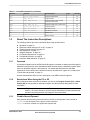

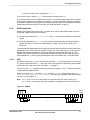


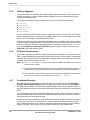
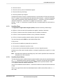


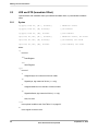
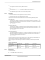

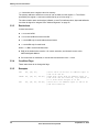

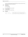
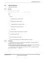
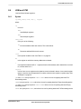


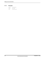

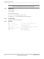
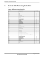


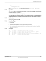

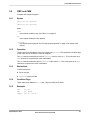
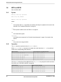

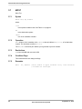


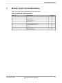


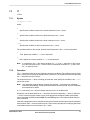
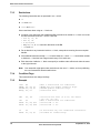
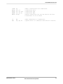
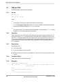
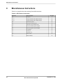
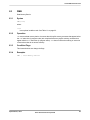
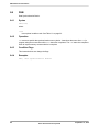
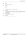
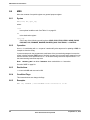


![[1] Cortex-M4 Devices Generic User Guide](http://vs1.manualzilla.com/store/data/005888690_1-fb40f3408e578b0f38de754df529f8db-150x150.png)