1
Lesson 11
Interrupt
1.
Overview
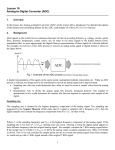
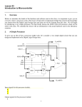
In this lesson, we introduce the general concepts about interrupts supported by the Cortex-M3 processor. We
will then discuss a specific interrupt example that utilizes an external triggered signal.
2.
General Concepts of an Interrupt
One of the methods to read an input from an I/O port is using the polling technique as you did in lab 1. Polling
is a technique to monitor an I/O port and to trigger an appropriate action when a change is detected. The general
idea is that the processor periodically reads the I/O port and determines if there is a change. If there is a change,
the processor will execute the subset of code to deal specifically with this change. Otherwise, the processor will
continue with normal operations.
Another (more efficient?) way to read and input for an I/O port is using an interrupt. Interrupt-based program
allows the processor to continue processing the main task without periodically checking for a change at an I/O
pin. Interrupt is an exception caused by an explicit request signal from a peripheral or hardware device. An
interrupt cause the automatic transfer of software execution outside of the normal programmed sequence. (e.g.
to provide service to the peripheral). When a peripheral or a hardware device needs service form the processor,
typically:
• It asserts an interrupt request to the processor,
• The processor completes the current instruction then it suspends the current task and jumps to an
Interrupt Service Routine (ISR) to service the peripheral,
• Then, the processor resumes the previously suspended task.
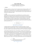
The Cortex-M3 processor supports vector interrupts. It means that when an interrupt occurs, the program jumps
to a specific memory location indicated by the Nested Vectored Interrupt Controller (NVIC). This controller
provides an efficient way to handle different exceptions. Exceptions numbers 1-15 are system exceptions as
shown in the table below.
Exceptions of number 16 or above are peripheral driven. We will mainly discuss these types of exceptions in
class. Parts of the NVIC are discussed in this lesson.
In order for the processor to recognize an interrupt request form a peripheral, the peripheral and processor must
be initialized and configured properly to enable the interrupt triggering mechanism. In general, the following
conditions must be true for an interrupt to occur:
1: The peripheral is configured properly. This step varies based on the peripheral. We will discuss a
specific example later in this lesson (EINT0).
2: The interrupt enable bit for the peripheral in the Interrupt Set-Enable Registers (ISERn registers) is
set. By default, all interrupt enable bits are cleared (disabled).
1
From The Definitive Guide to ARM Cortex-M3 and Cortex-M4 Processors, Joseph Yiu, Elsevier, 3nd ed, 2014.
3: The priority level for the peripheral is configured properly in the Interrupt Priority Registers (IPRn
registers). In order for this interrupt to occur, this priority level must be higher than or the same as the
priority level set in BASEPRI register. Note that the lowest number is the highest priority. By default,
the priority level is 0 in BASEPRI register. Also, by default the priority level is zero for all
peripherals. It means that default values for these registers are ok to use in your program without an
modifications.
4: The global interrupt bit is enabled (bit 0 in PRIMASK register = 0). By default bit 0 of PRIMASK is
0 (enabled). In general, you won’t need to modify this register, but if necessary, you can use the
following instructions to enable or disable the global interrupt bit:
CPSIE I
CPSID I
; Clear PRIMASK (enable interrupts)
; Set PRIMASK (disable interrupts)
You can also use the MRS instructions to enable/disable disable the global interrupt bit. For example,
MOV R0, #1
MRS PRIMASK, R0
; write 1 to disable all interrupts
MOV R0, #0
MRS PRIMASK, R0
; write 0 to enable all interrupts
or
2
5: The peripheral asserts the interrupt request which sets the interrupt flag.
Once an interrupt request has been asserted by the peripheral and recognized by the processor, the processor
needs to service the peripheral which causes the following conditions:
1: Suspension of the main program
• Current instruction is completed
• Suspend execution and push 8 registers (R0-R3, R12, LR, PC, PCR) on the stack
• LR set to 0xFFFFFFF9 which indicates interrupt return
• IPSR set to interrupt number
• PC set to ISR address
2: The ISR is executed
• Process the interrupt request by the peripheral
• Clears the flag that requested the interrupt
• Exit ISR by executing BX LR
3: Resume normal operation
• Pulls 8 registers (R0-R3, R12, LR, PC, PCR) from the stack
• Return to the next instruction in the previously suspended task.
Interrupt Service Routine (ISR) is a subroutine that is executed when an interrupt request occurs. Generally,
each potential source of interrupt would have a specific ISR. In most cases (except for the SysTick interrupt),
the ISR must clear the flag that caused the interrupt. Failing to clear the flag will trigger continuous ISR
execution (endless loop). After the ISR provides the necessary service, it will return to the main program by
executing the BX LR instruction.
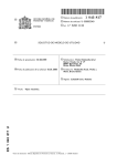
In the vector interrupt system, each source (or each peripheral or hardware device) of interrupt has an associated
32-bit vector that points to the address of the first instruction in the ISR that handles the exception. These
vectors are stored at the beginning of the ROM. Table 50 (shown below) in the LPC17xx User Manual
contains the interrupt vector location for different interrupt source/peripheral. Note that the Vector Offset value
is the offset number from the beginning of the memory space (ROM starts at address 0x00000000). When an
interrupt occurs, the processor determines which exception number is activated, then calculates the starting
address of the ISR. The address is then used to update the PC. For example, if an External Interrupt 0 (EINT0)
requests an interrupt, the processor calculates the PC as:
Offset = Exception Number * 4 = 34 * 4 = 136 = 0x88
PC = [Offset] ;this means that the 32-bit value stored at address 0x00000088 which
points to the first instruction in the ISR is used to update the PC,
So, if the ISR starts at address 0x154, then the value stored at offset 0x88 in the vector
table is 0x00000154. And PC = 0x00000154 after the interrupt requests is asserted.
3
From Table 50 in the LPC17xx User manual, NXP Semiconductors, 2010.
4
From Table 50 in the LPC17xx User manual, NXP Semiconductors, 2010.
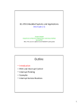
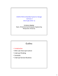
Note that the ISR can reside anywhere in the code memory (ROM), so how do we manage the memory space so
that the processor can point to the right address for the correct ISR? From a programming perspective, we can
write the ISR as regular subroutine but with specific names. These predefined ISR names are provided in the
startupLPC17xx.s file provided with the Keil uvision software. A screenshot of the startupLPC17xx.s showing
some of the predefined ISR names is shown in the figure below. For example, if we want to create an ISR for
EITN0, then the name for the ISR should be EINT0_IRQHandler. The compiler will place the memory address
of this ISR in the appropriate offset in the vector table (0x88 in this case).
5
3.
Example of an Interrupt – EINT0 (External Interrupt)
Let’s look at an example of an interrupt. The peripheral that we will use in this example is the External Interrupt
0 (EINT0).
Step 1: Setup the peripheral (EINT0)
Since this peripheral shares the same pin with other functions (e.g. GPIO P2.10), we will first need to set it up
to function as an External Interrupt 0 Pin. This is done by
6
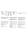
Setting bit 21:20 in the PINSEL4 (0x4020C010) register to “01”. This information is
shown in Table 83 in the LPC17xx User manual.
Next, we will need to set the pin to detect rising edge changes (for this example) at the pin. These edges will
cause interrupts. This can be achieved by
Setting bit 0 of the EXTMODE register (0x400FC148) to 1 to set EINT0 to recognize
edges (not level). This information is shown in Table 11 in the LPC17xx User manual.
Setting bit 0 of the EXTPOLAR register (0x400FC14C) to 1 to set EINT0 to recognize
RISING edges (not FALLING). This information is shown in Table 12 in the LPC17xx User
manual.
Step 2: Enable EINT0 Interrupt
By default, all external interrupts are disabled. So, we need to enable specific interrupt so that the processor can
service the peripheral when requested. We can enable EINT0 interrupt by
Setting bit 18 of the ISER0 register (0xE000E100) to 1 to enable EINT0 interrupt. This
information is shown in Table 52 in the LPC17xx User manual.
Step 3: Set the Priority Level for EINT0 (optional)
By default, all interrupts are set at level 0 which is the highest priority. This default priority is good to use in
programs, so you don’t have to do anything. However, if you want to set the priority of EINT0 to another level,
you will need to
Set bits 23:19 of the IPR4 register (0xE000E408) to the appropriate binary number
representing the priority level. For example,
If bits 23:19 = “00010”, then the priority is set at level 2
If bits 23:29 = “11111”, then the priority is set at level 31 (lowest priority)
This information is shown in Table 66 in the LPC17xx User manual.
Step 4: Enable the Global Interrupt Bit (optional)
By default, the processor is configured to recognize any interrupts that are enabled (e.g. in step 2). It means that
you don’t have to do anything to enable this bit. This is indicated by bit 0 of the PRIMASK register. If this bit =
0, all interrupts can be activated if enabled in step 2. If this bit is 1, all exceptions (except NMI) are disabled.
Recall that you can use the following instructions to enable or disable the global interrupt bit:
CPSIE I
CPSID I
; Clear PRIMASK (enable interrupts)
; Set PRIMASK (disable interrupts)
Step 5: Develop an Interrupt Service Routine (ISR) for EINT0
In order for the processor to jump to right code for EINT0 interrupt, the ISR must be named as:
7
EINT0_IRQHandler
For example, in C, the function declaration should be
void __asm EINT0_IRQHandler(void)
The first task the ISR should perform is to save the contents of all the registers (r4-r12) that will be used in this
subroutine. For example, if your subroutine uses r4 and r5 as temporary storage, you should save these registers
by
PUSH {r4-r5}
The next step is to process the interrupt request. This is an application dependent step. For example, we can
write an application to keep a count of the number the INT0 pushbutton is pressed.
The next step is very important: clearing the interrupt flag. If your ISR returns without clearing the interrupt
flag, the interrupt will endlessly occur (infinite loop). For EINT0, we can clear the interrupt flag by
Write ‘1’ to bit 0 of the EXTINT register (0x400FC140). This information is shown in
Table 10 in the LPC17xx User manual.
Before returning to the main program, your subroutine should restore all the temporary registers (r4-r12) that
are used in the ISR. For example, if registers r4 and r5 are pushed on the stack at the beginning of the ISR, these
registers should be popped as:
POP {r4-r5}
The last instruction of the should be
BL
LR;
return from subroutine
Exercise: Write code to setup EINT0 interrupt. Keep a count of the number of interrupt occurrences.
Notes about debugging with interrupts:
• Cannot use single step
• Use breakpoints and run option instead
4.
References
[1].
[2].
[3].
[4].
[5].
Joseph Yiu, The Definitive Guide to ARM Cortex-M3 and Cortex-M4 Processors, Elsevier, 3rd ed, 2014.
Jonathan Valvano, Introduction to ARM Cortex-M Microcontroller, 4nd ed, 2013.
ARMv7-M Architecture Reference Manual, ARM Limited, 2010.
LPC17xx User manual, NXP Semiconductors, 2010.
Cortex-M3 Technical Reference Manual, ARM Limited, 2010.
8
/*--------------------------------------------------------------Lesson 11: EINT0 interrupt example
*--------------------------------------------------------------*/
#include "LPC17xx.h"
#include "LED.h"
// Device header
void __asm EINT0_IRQHandler(void);
void __asm EINT0_Init(void);
int count; // Reserve a 32-bit word at address0x10000000
/*----------------------------------------------------------Main: Initialize
*-------------------------------------------------------*/
int main (void) {
count = 0;
LED_Init();
EINT0_Init ();
/* Initialize LEDs
/* Initialize EINT0 interrupt
*/
*/
while (1){} // endless loop -- do nothing, wait for interrupt
}
void __asm EINT0_Init(void)
{
// ------------------- Step 1 -----------------------------------//Setup pin to be EINT0 in PINSEL4 register
LDR R0, =0x00100000 // R0= OR mask to set bit 20, other bits unchanged
LDR R1, =0xffdfffff // R0= AND mask to clear bit 21, other bits unchanged
LDR R2, =0x4002C010 // R2= Address of PINSEL register
LDR R3, [R2]
ORR R3, R3, R0
// set bit 20
AND R3, R3, R1
// clear bit 21
STR R3, [R2]
// write back to PINSEL4 register
//Setup Mode to be edge in EXTMODE register
LDR R2, =0x4002C148 // R2= Address of EXTMODE register
LDR R3, [R2]
ORR R3, R3, #1
// force bit 0 = 1 for edge
STR R3, [R2]
// write back to EXTMODE register
//Setup Polarity to
LDR R2, =0x4002C14C
LDR R3, [R2]
ORR R3, R3, #1
STR R3, [R2]
be rising edge in EXTPOLAR register
// R2= Address of EXTPOLAR register
// force bit 0 = 1 for rising edge
// write back to EXTPOLAR register
9
// ------ Step 2: Enable interrupt for peripheral (EINT0) in ISER0 reigster
LDR R0, =0x00040000
// R0= OR mask to set bit 18, other bits unchanged
LDR R2, =0xE000E100
// R2= Address of ISER0 register
ORR R3, R3, R0
// force bit 18 = 1 to enable interrupt for EINT0
STR R3, [R2]
// write back to ISER0 register
// ----- Step 3: Setup priority for peripheral (EINT0) -- default ok
// ----- Step 4: Enable global interrupt bit -- default ok
}
BX LR
// return
// ----- Step 5: ISR for EINT0------------------------------------void __asm EINT0_IRQHandler(void){
// Save registers (r4-r12) if used in ISR
// Processing: increment a count in count
LDR R0, =0x10000000
// R0= address of count in data RAM
LDR R1, [R0]
ADD R1, R1, #1
// increment count
STR R1, [R0]
// Clear EINT0 interrupt flag in EXTINT register
LDR R0, =0x400FC140
// R0= address of EXTINT register
MOV R1, #1
STR R1, [R0]
// clear EINT0 flag by writing 1 to bit 0
// Pull registers (r4-r12) if used in ISR
}
BX LR
// Return from ISR
/*---------------------------------------------------------* end of file
*---------------------------------------------------------*/
10