1
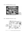
ICSP:
2x3 pin header
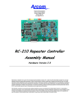
Used to program Atmega with bootloader. The number 1 on both sides
of the board indicates cable pin1 position.
Used to upload sketches on Atmega ICs without bootloader (available
only in Arduino IDE versions 0011 and 0012).
JP0
3 pins jumper
When in position 2-3, this jumper enables serial connection (through
X1 connector) to/from computer/devices. Use this as default position.
When in position 1 -2, it disables serial communication, and enables
external pull -down resistors on pin0 (RX) and pin1 (TX). Use this only
to prevent noise on RX (that seems incoming data to Atmega), that
sometimes makes sketch not starting.
When removing this jumper, serial communication
pin0 and pin1 work as a normal (flo ating) digital
more digital pins are needed, but only when serial
not necessary. External pull-down/pull -up resistor is
is disabled, and
pin. Useful when
communication is
required.
JP4
2 pins jumper
When in position 1 -2, this jumper enables auto reset feature, useful
when uploading a sketch to Arduino, resetting Atmega automatically.
It makes unnecessary to press reset button (S1) when uploading
sketches.
Be sure that computer COM Port speed is set to 19200bps otherwise
auto reset will not work properly.
If removed, disables auto reset feature. Very useful to prevent
undesired Atmega reset when using sketches that needs serial
communication.
Auto reset works with DTR pulse on serial pin4. Sometimes Arduino
senses a DTR pulse when connecting X1 (serial connector) and some
softwares sends a DTR pulse when it starts or when it closes , that
makes Atmega reset when not desired.