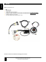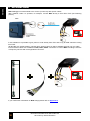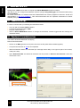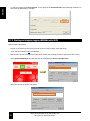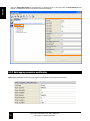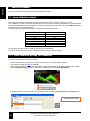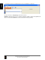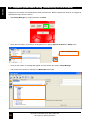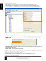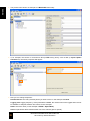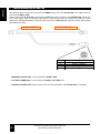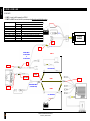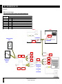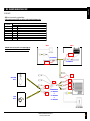
1
ENGLISH M40 DATALOGGER User Manual ENGLISH M40 DATALOGGER User Manual Rev.05 Release FW 1.42 2014 - GET by Athena Evolution. All right reserved. The content of this document, part of this document, could be copied, transferred, send or memorized on other form without the written consent of GET by Athena Evolution . GET has the right to change without notice the content of this manual. WARNING: M40 DATALOGGERS are not homologated for road circulation. 2 M40 DATALOGGER User Manual Rev.05 2014 GET by Athena Evolution 1 M40 KIT ................................................................................................................................................ 6 2 GPS WORKING PRINCIPLE ................................................................................................................ 7 3 SUGGESTIONS AND PRECAUTIONS DURING INSTALLATION ...................................................... 7 3.1 Precautions for M40 installation ........................................................................................................... 7 3.2 GPS antenna installation ...................................................................................................................... 7 3.3 M40 system installation ........................................................................................................................ 8 4 M40: CONTROLS AND INDICATORS ................................................................................................. 9 4.1 Diagnosis LEDs .................................................................................................................................... 9 5 M40 WIRING LOOMS......................................................................................................................... 10 6 FIRMWARE, CONFIGURATION, SETUP FOR M40 DATALOGGER ............................................... 11 7 USING M40 DATALOGGER .............................................................................................................. 12 7.1 Importance of data logging ................................................................................................................. 12 7.2 Getting started .................................................................................................................................... 12 7.2.1 GPS fixing ........................................................................................................................................... 12 7.3 Data logging ........................................................................................................................................ 12 7.4 Internal accelerometers ...................................................................................................................... 13 8 USING M40 WITH A PC ..................................................................................................................... 14 8.1 Connection to a pc .............................................................................................................................. 14 8.2 Download of recorded sessions ......................................................................................................... 14 8.3 Visualizing recorded sessions ............................................................................................................ 17 8.4 Set the default track in the device ...................................................................................................... 19 8.5 Track creation from a recorded session ............................................................................................. 20 8.6 Instrument setup download and updating .......................................................................................... 22 8.6.1 Instrument setup download and updating with DATA MANAGER software ....................................... 22 8.6.2 Instrument setup download and updating with GATE software .......................................................... 23 8.7 Starting and stopping logging (MANUAL) .......................................................................................... 25 8.7.1 Starting and stopping logging (MANUAL) with DATA MANAGER ..................................................... 25 8.7.2 Starting and stopping logging (MANUAL) with GATE ........................................................................ 26 8.8 Time syncronization (from pc) ............................................................................................................ 28 8.8.1 Time syncronization with DATA MANAGER ...................................................................................... 28 8.8.2 Time syncronization with GATE .......................................................................................................... 28 8.9 M40 configuration ............................................................................................................................... 30 8.9.1 M40 configuration with DATA MANAGER .......................................................................................... 31 8.9.2 M40 configuration with GATE ............................................................................................................. 32 8.9.3 Data logging parameters modification ................................................................................................ 34 8.9.4 Change of system time ....................................................................................................................... 36 8.9.5 Lap trigger modification....................................................................................................................... 36 8.9.6 GRSY channel setting......................................................................................................................... 36 8.9.7 Serial protocol setting ......................................................................................................................... 37 8.9.8 CAN parameters setting...................................................................................................................... 37 8.10 M40 setup properties modification ...................................................................................................... 38 8.10.1 M40 setup properties modification with DATA MANAGER ................................................................ 38 8.10.2 M40 setup properties modification with GATE ................................................................................... 40 8.10.3 GPS parameters setting...................................................................................................................... 42 8.10.4 Comment, driver and vehicle setting .................................................................................................. 42 8.11 Firmware update ................................................................................................................................. 43 9 M40 TECHNICAL CHARACTERISTICS ............................................................................................ 44 APPENDIX 1: M40 SETUP.............................................................................................................................. 45 1 ANALOGUE CHANNELS ................................................................................................................... 46 1.1 Linear calibration example .................................................................................................................. 46 1.1.1 Linear calibration by using DATA MANAGER ................................................................................... 46 1.1.2 Linear calibration by using GATE ...................................................................................................... 49 1.2 GEAR on analogue input calibration .................................................................................................. 52 1.2.1 GEAR on analogue input calibration by using GATE ......................................................................... 52 1.2.2 GEAR on analogue input calibration by using GATE ......................................................................... 55 1.3 TPS setup (available only for GATE software) ................................................................................... 59 1.4 Suspension potentiometer setting (available only for GATE software) ............................................. 62 2 SWITCH CHANNELS (ONLY M40 EXPANSION AND PLUS MODELS) .......................................... 65 2.1 Adding a SWITCH MAP-SWITCH BUTTON channel ........................................................................ 65 2.2 Adding a BEACON channel ................................................................................................................ 69 3 CAN CHANNELS ................................................................................................................................ 72 M40 DATALOGGER User Manual Rev.05 2014 GET by Athena Evolution 3 ENGLISH INDEX ENGLISH 3.1 Adding a CAN channel ....................................................................................................................... 72 4 INPUT CAPTURE CHANNELS (IC CHANNELS) .............................................................................. 77 4.1 IC channel calibration (connected to a wheel speed sensor) ............................................................. 77 4.2 IC channel calibration (connected to a RPM sensor) ......................................................................... 81 5 “WATCH” function ............................................................................................................................... 82 5.1 Start and stop “WATCH”: real time channel visualization .................................................................. 82 5.2 “WATCH” channel calibration ............................................................................................................. 86 5.3 Setting channel zero in “WATCH” ...................................................................................................... 87 5.4 Setting channel offset in “WATCH” ..................................................................................................... 88 APPENDIX 2: CONNECTORS M40 STD. – EXP. - PLUS.............................................................................. 89 1 “MAIN” CONNECTOR (M40 STD. - EXP. - PLUS) ............................................................................ 89 2 “EXP” CONNECTOR (M40 STD. - EXP. - PLUS) .............................................................................. 90 3 “EXP1” CONNECTOR (ONLY M40 EXP. - PLUS) ............................................................................. 90 4 “EXP2” CONNECTOR (ONLY M40 PLUS) ........................................................................................ 91 5 “USB” CONNECTOR (M40 STD. - EXP.- PLUS) .............................................................................. 91 APPENDIX 3: WIRING LOOMS FOR M40 CONNECTION ............................................................................ 92 1 MULTILINK WIRING code GL-0018-AA ............................................................................................. 92 2 EXPANSION WIRING code GL-0041-AA.......................................................................................... 93 3 EXPANSIONE WIRING code GL-0042-AA ........................................................................................ 94 4 EXPANSION WIRING code GL-0043-AA.......................................................................................... 95 5 DATA DOWNLOAD WIRING code GL-0019-AA ................................................................................ 96 6 POWER WIRING code GL-0036-AA .................................................................................................. 97 7 POWER WIRING code GL-0037-AA .................................................................................................. 98 8 POWER – DATA WIRING code GL-0038-AA .................................................................................... 99 9 POWER – DATA WIRING code GL-0039-AA .................................................................................. 100 APPENDIX 4: M40 CONNECTION DIAGRAMS ........................................................................................... 101 1 GP1 EVO - M40 (BATTERY LESS CONFIGURATION) ............................................................... 101 2 GP1 EVO - LC1 EVO - M40 ......................................................................................................... 102 3 LC1 EVO - M40 (ANALOG CONNECTION) .................................................................................. 103 4 LC1 EVO - M40 (CAN BUS CONNECTION) ................................................................................. 104 5 M40 - ANALOG SENSORS SUPPLIED AT 5VDC ......................................................................... 105 6 M40 - ANALOG SENSORS SUPPLIED AT 12VDC ....................................................................... 106 7 M40 - FREQUENCY SENSORS SUPPLIED AT 12VDC ................................................................ 107 4 M40 DATALOGGER User Manual Rev.05 2014 GET by Athena Evolution thank you for choosing a GET DATA ACQUISITION AND ANALYSIS SYSTEMS by Athena Evolution. We are sure that our passion and experience will help you to express successfully in all competitions, we ask you to read carefully this user manual. We are confident that this will help you in the use of you new product GET by Athena Evolution. M40 STANDARD – M40 EXPANSION – M40 PLUS, due to GPS technology, can log not only signal from connected sensors but also data concerning trajectories and vehicle speed. Acquisition and configuration of M40 datalogger (with firmware release less than 1.30) are done via GATE software, MX2 (analysis), Download Manager (device synchronization) and Setup Manager (Setup management).The firmware release over than 1.30 are manage by DATA MANAGER software. This manual is dedicated to illustrate to the end user information on M40 datalogger functions. Otherwise specified, functions described are in Standard (M40 STD.) Expansion (M40 EXP.) and PLUS (M40 PLUS). Different versions of M40 are the followings: Characteristic/function Integrated tri-axle accelerometer Analogue input (0-5V) Frequency input (open collector 0-5V, freq. 0 20kHz) External beacon input CAN connection Maximum CAN channels CAN channel transmission CAN channel reception Logging rate (Hz) in each channel Auxiliary power output 5 VDC @ 1A Auxiliary power output VBB Logging trigger channel Switch on delay Data recording switch on delay GPS logging frequency (Hz) Average precision GPS module (m) GPS antenna Start/stop data logging signalling led GPS status signalling led Integrated Real Time Clock (RTC) Internal clock updating Time zone setting Internal memory (GB) USB communication port Firmware update Interface software Case material Protection grade Dimension length x width x height (mm) Weight (g) M40 STD 3 MODEL M40 EXP 6 M40 PLUS 9 2 3 5 2.0 High Speed (bitrate 125 kb/s, 250 kb/s, 500 kb/s, 1Mb/s; Intel and Motorola protocol) 128 1 – 10 – 20 – 50 – 100 – 500 User selectable (speed, RPM, manual, etc) User selectable (via software) User selectable (via software) 5 – oversampled to 10 2.5 Active 5V, gain 28dB, SMA connector Yes, with backup battery Manual (via PC) or automatic (from GPS) Via PC Up to 16 fw user updatable via PC DATA MANAGER (GATE for rel. fw <1.30) Anodized aluminium IP68 92 x 66 x 20 250 260 270 Otherwise specified (M40 STANDARD, M40 EXPANSION o M40 PLUS) M40 refers to instruction and/or function for all three data loggers. CAUTION: channels not available on M40 are locked from GATE software and the user can not modify this. M40 DATALOGGER User Manual Rev.05 2014 GET by Athena Evolution 5 ENGLISH Dear customer, 1 M40 KIT ENGLISH M40 kit is comprehensive of: box M40 datalogger 1 GPS antenna 1 power cable, code GL-0038-AA 1 expansion cables JST-Binder for the connection of external sensors (only M40 EXPANSION) 2 expansion cables JST-Binder for the connection of external sensors (only M40 PLUS) 1 USB-JST cable for pc connection 1 CD with software and manuals electronic copy • • • • • • • • NOTE: kit content can be different accordingly to the versions. 6 M40 DATALOGGER User Manual Rev.05 2014 GET by Athena Evolution GPS WORKING PRINCIPLE GPS (Global Positioning System) system, on which your GET system is based, uses a spherical positioning algorithm in order to identify the position of receiver the signal coming from satellites. Measuring the time needed by a radio signal to cover the distance satellite-receiver and knowing the precise position of at least 4 satellites, it is possible to identify the 3D position of the receiver. 24 GPS satellites, arranged in orbits inclined at 55 degrees to the equator, are between 18000 and 20000 km from the Earth and they rotate completely in 12 hours. Satellites transmit signals of 1.2 and 1.5 GHz (to avoid errors coming from atmosphere refraction) originated by a single oscillator (atomic clock). Transmitted data contain information on satellite’s orbit and time signal (messages of Ephemeris) that permit to the receiver to define position on earth surface. Time lapping is done via GPS: this solution avoid uncomfortable beacons side the track and help to have timing references during data analysis. GPS is a stochastic algorithm and it is strictly linked to the correct signal receiving. In case of electromagnetic or ambient interferences the quality of data is not guaranteed. The minimum received number of satellites in order to guarantee a proper quality in time lapping is 5. 3 SUGGESTIONS AND PRECAUTIONS DURING INSTALLATION We recommend to read carefully following chapters in order to get the best during the installation of M40 in your vehicle. WARNING: A WRONG INSTALLATION COULD CAUSE SERIOUS TROUBLES TO PEOPLE AND/OR THINGS 3.1 Precautions for M40 installation Before proceeding with installation of M40 onto a vehicle please observe the following rules: Work in a user friendly environment (example: enough working space) Disconnect battery wirings Put all removed vehicle parts in a safe place avoiding to damage them Installation in vehicle with internal combustion engine has to be done with the engine cold: during the installation you could be in contact with engine or chassis parts • During the job be really careful to connectors and wirings • Keep washers, bolts and nuts in a safe place during M40 installation • During installation avoid that any part installed interfere with driving parts or with the driver • • • • 3.2 GPS antenna installation In order to install properly the GPS antenna please refer to the following instructions: • be really careful during GPS antenna movement: Avoid shocks and verify that connector and cable are in a perfect shape M40 DATALOGGER User Manual Rev.05 2014 GET by Athena Evolution 7 ENGLISH 2 ENGLISH • fix the antenna outside the vehicle: obstacles near to the antenna could cause a reduction to the receiving capabilities of the sensor. A wrong position could cause an incorrect lap timing, wrong data acquisition and wrong trajectories • do not twist the antenna cable around other cables (especially around high voltage plugs wiring): this could cause inductive interferences and cause problems during the functioning • let pass the antenna cable as far as possible from spark plugs and other electromagnetic field. In motorbikes it is preferable to run the cable out of the chassis but in any case in a protected zone • fix the GPS connector to the ANTENNA input in MD40 without use excessive torque: do not use tools Some suggestions to fix the antenna: Speed bikes: fix the antenna in the far back part of the motorbike away from heat sources (exhaust) or in cockpit area (on top of it). Off-road bike: fix the antenna on handlebar handle pad. Car: fix the antenna on top of the roof. Kart: fix the antenna on the higher part of front number plate, if needed manufacture a support to address the sensor in the proper direction. 3.3 M40 system installation M40 data loggers are done in order to be fixed easily inside all vehicles. For electrical connections please read Appendix 2 and Appendix 3 of this manual. With dedicated cables it is possible to connect directly to ECU by Athena Evolution (example GP1EVO) via CAN bus. The following figure shows in principles a typical installation of a M40 into a motorbike. M40 PC GPS antenna Sensor 8 M40 DATALOGGER User Manual Rev.05 2014 GET by Athena Evolution M40: CONTROLS AND INDICATORS ENGLISH 4 1 5 3 6 2 7 4 9 8 1: M40 DEVICE 2: MAIN connection cable 3: EXP connection cable 4: USB connection cable 5: red diagnosis led 6: green diagnosis led 7: GPS antenna connector 8: EXP1 connection cable (only for M40 EXPANSION and M40 PLUS) 9: EXP2 connection cable (only for M40 PLUS) 4.1 Diagnosis LEDs M40 data logger has got two LEDs. The following table shows their meaning: Cond. 1 2 3 4 5 6 7 Led Green Green Green Green Red Red Green + Red Status Off On fix Blinking (frequency 1Hz) Blinking (frequency 2Hz) On fix Off Blinking (frequency 1Hz) Meaning The device is off The device is on Acquiring data The memory is full Not adequate satellites reading Adequate satellites reading The device is connected to PC It is possible that some combinations occur. For example, both LEDs on fix: in this case the instrument is on (condition 2) but with a low satellite reading (condition 5). Except for condition 7, status of M40 will be defined by a combination of two LEDs conditions: 2 + 5, or 2 + 6, or 3 + 5 , etc. M40 DATALOGGER User Manual Rev.05 2014 GET by Athena Evolution 9 5 M40 WIRING LOOMS ENGLISH M40 dataloggers could be linked to the vehicle (or sensors) with specific cables. With “multilink” cable it is possible, for example, connect M40 directly to ECU GP1 EVO (see following picture): DATALOGGER ECU In this situation it is possible to give power to m40 directly from ECU and to log all CAN channels coming from ECU. All data like rpm, throttle position, injection time, advance time, etc will be available through only one cable. Interconnection cables are available for EXP, EXP1, EXP2 connectors to connect M40 to analogue sensors or frequency sensors with 3 wirings Binder connector. If you need further information on M40 wirings please refer to Appendix 3, 10 M40 DATALOGGER User Manual Rev.05 2014 GET by Athena Evolution FIRMWARE, CONFIGURATION, SETUP FOR M40 DATALOGGER ENGLISH 6 M40 is based on three internal software: • Firmware: this is necessary to guarantee the instrument functioning, • Configuration: this is necessary for base setup of the instrument like serial number and identify number. • Setup: this is needed by M40 in order to get all information about sensors, calibrations, logging frequencies, etc. You can adjust M40 setup with CONFIG DATALOGGER software (if you are using DATA MANAGER software) or Setup Manager (it’d included into the software suite GATE). Some channels cannot be modified by the user in order to avoid malfunctioning M40 DATALOGGER User Manual Rev.05 2014 GET by Athena Evolution 11 7 USING M40 DATALOGGER ENGLISH Following chapters are written to explain simple rules for the use of the instrument and information given by LEDs. 7.1 Importance of data logging Logging data during test sessions or test bench is becoming more and more important because: • • • • • • You can reduce setup time on the vehicle You can solve driving mistakes You can evaluate vehicle behaviour statically and dynamically You can visualize all logged parameters You can check continuously engine and chassis performances You can see lap times once downloaded 7.2 Getting started Please read carefully following chapters for an optimal use of M40. 7.2.1 GPS fixing You need to “fix” satellites in order to get trajectories and lap times with MX2 software. The minimum number of satellites to get a correct acquisition is 5. In fixed application (test bench) you do not need GPS. NOTE: M40 continue to search satellites during logging. This permit to start the acquisition also without GPS data. In this case it will be probable that trajectories visualization (done via software) could be compromise. The evidence of this phenomena are fast variations on the position of vehicle (spike), up to some kilometres!!!! 7.3 Data logging Start and stop of data logging could take place with the following modes: • Manual: starting the acquisition via software • Automatic: - from vehicle speed (Speed) both with GPS or with wheel speed (only with installed sensor) - From engine speed (RPM) - defining a special threshold value from any given input/channel of M40 In standard configuration start/stop are MANUAL. In this condition it is necessary to connect a pc with DATA MANAGER in order to record data. For further information on data logging start/stop see chapter 8.7 and 8.9.3. To modify logging start/stop mode use Config Datalogger. 12 M40 DATALOGGER User Manual Rev.05 2014 GET by Athena Evolution ENGLISH 7.4 Internal accelerometers M40 has got three accelerometers as described in the picture: + - - + + - Values are logged automatically by M40 and therefore can be used with MX2. Internal accelerometers are System Channels, in M40 setup. Logical names are: • ACCX • ACCY • ACCZ You can see these names in Setup Manager and in Channel Bar of MX2. You can zero of these sensors with WATCH function in Setup Manager (read Appendix 1 – cap. 5 of this manual). M40 DATALOGGER User Manual Rev.05 2014 GET by Athena Evolution 13 8 USING M40 WITH A PC ENGLISH Management of M40 is done with a computer with DATA MANAGER software installed. With the pc you can configure and calibrate channels (using Config Datalogger) and download data (using Download Data). For further information on software read DATA MANAGER user manual (supplied in electronic format and downloadable in http://www.getdata.it). This manual describes also the operative instructions for GATE software (if the procedures are different) 8.1 Connection to a pc In order to connect with a pc following the instructions below: • • • • Use a pc with an installed GATE software Connect the download cable to M40 Plug the USB into the PC Start the DATA MANAGER software to manage the download, visualize logged data and manage the instrument setup. 8.2 Download of recorded sessions You need to download data before analyzing Follow instructions below: • Switch on the M40 (greed led on fix) and connect to the PC (both LEDs will blink together). • Verify that all instruction in 8.1 are accomplished. • Wait that Windows detect the instrument (the message will be likely in the right low part of the monitor, nearby the clock). • Open Download Data and wait that instrument will be present in Devices and Sessions: select the device with a click Test 14 M40 DATALOGGER User Manual Rev.05 2014 GET by Athena Evolution ENGLISH • If needed, you can stop acquisition pressing Stop Acquis in the right part of Download Data page. • Click on to the cross at the left of the name in order to see stored sessions’ list. • Select the needed session with left click(blue background). • Click on Download File and wait until the end of operation. • Data are stored in the folder: “Base directory” \ “Track” \ “Session” \ “Vehicle Name” \ “Run_name” Where: Base directory: it is the main folder of storage path (the hard disk letter is also included). It is defined by Base directory field in Download Data. The default directory is C:\WinTAXWorkspace. A different path can be selected by click on Base directory selection button. Track: it is the first sub directory of storage path. User can modify the Track field in Download Data in order to change the directory name. PLEASE NOTE: the directory is always create by the software, the default settings is Track. Session: it is the second sub directory of storage path. User can modify the Session field in Download Data in order to change the directory name. PLEASE NOTE: the directory is always create by the software, the default settings is Session. Vehicle Name: it is the third sub directory of storage path. User can modify the Vehicle Name field in data logger configuration (see Config Datalogger section of this manual and the datalogger User Guide for more informations) to set a new folder name. Run_name: it is the last sub directory of storage path. Its name is Run_ followed to a progressive session index number created by the data logger (in our example it is represented with XXX). Also the Run Comment) text (if it is present) will be added to the folder name. M40 DATALOGGER User Manual Rev.05 2014 GET by Athena Evolution 15 ENGLISH The picture below show the Data Storage Settings Area: Base directory selection button Base directory Track Session Run name Test For example the storage path of picture above will be: c:\WinTAXWorkspace\ Track \ Session \ Car \ Run_XXX_Test Where: Car is set in Vehicle Name field of data logger setup Run_XXX is the progressive index of data • At the end of download a message will appear: the device has to be disconnect. • Confirm the operation pressing OK: the window of Download Data will disappear. For further information on Download Data use read DATA MANAGER user manual. 16 M40 DATALOGGER User Manual Rev.05 2014 GET by Athena Evolution In order to visualize downloaded sessions you need to use MX2 (the analysis software of DATA MANAGER freeware) and/or WINTAX (require a payment license) Read following instructions: • Start MX2 by clicking on the desktop icon: • Wait a few seconds: probably will appear demo project (if a new project has not been created). • Create a new project by clicking New Project in File menu. NOTE: you can use an old project by selecting Open Project in File menu. If you use the Demo project you cannot save changes (example: sessions and new channels). For this reason it is suggested to create a brand new project. M40 DATALOGGER User Manual Rev.05 2014 GET by Athena Evolution 17 ENGLISH 8.3 Visualizing recorded sessions Open Browser Bar and search the needed session in the tree on the left. ENGLISH • Select the session in the column File name • Apply the track (or create a new one) to the selected session with the track selection window. This is needed to obtain laps’ division (if needed): SELECTED TRACK “OK” BUTTON “CREAT NEW TRACK” BUTTON NOTE: usually logged data contains information about the track used during the session. Sometimes could happen that this information is missing due to, for example, lack of synchronization of track library with the device. Until you do not associate a track to the session, you will see only lap 0. Once linked the session to the track you will see laps division: this division will be available in all accesses to the same session. Lap times are linked to start-finish line: if you have official lap times and you need to compare directly to logged data it is needed to select a track with a start-finish line as close as possible to the real one. LAPS DIVISION IS UNAVAILABLE WITHOUT GPS INFORMATIONS (IF THE LAP TRIGGER PROPERTY IS SET AS GPS). • If the track is not in the library, or there are more tracks (usually with different start-finish line), for the needed session the window for the selection of the map could appear: you need to select the track between proposed or you need to create a new one with Create New – for the procedure refer to chapter 8.5 of this manual. 18 M40 DATALOGGER User Manual Rev.05 2014 GET by Athena Evolution on the icon Channel Bar (under Browser Bar). ENGLISH • Ad channels by clicking • You can now analyze data and lines. 8.4 Set the default track in the device To set the default device’s track follow the instructions: • Switch on the device (green led fix) and connect to PC ( both led will blink). • Verify that all condition of 8.1 are satisfied. • Wait until the device is recognized by Windows (usually the message in the low right part of the screen). • Start Config Datalogger by clicking on the button in starting window of DATA MANAGER. • Click the icon Send track on main instrument bar, or select Sync Track Library from Setup menu. “Send Default Track” ICON A message will appear at the end of the operation. PLEASE NOTE: BY SETTING THE DEFAULT TRACK THE LAPS DIVISION WILL BE ALREADY AVAILABLE ON WINTAX SOFTWARE (THIS OPERATION IS NOT NECESSARY FOR MX2 SOFTWARE). M40 DATALOGGER User Manual Rev.05 2014 GET by Athena Evolution 19 8.5 Track creation from a recorded session ENGLISH The creation of new track it is possible by logging data as described in chapter 7.3. After the download of the session (read chapter 8.2) proceed as follows: • Open MX2 and create a new project (read chapter 8.3). • Select the session: software will shows this window. • Push Create New button: a new track will be created with the name new_track in Available Tracks list. This track will be without start-finish line, split points and sectors. • Define a new start-finish line: click on Finish Line in the left menu • Define the line on the track (FL) by clicking on the track picture and drag the mouse (keeping left button pressed), and realize the line with needed dimensions. Release mouse button: the start-finish line will be set. The start-finish line must cross the map, otherwise laps won’t be calculated. It is advised to create a perpendicular line to the trajectory with a proper length, not too long (avoiding crossing other parts of the track) not too short (otherwise you could not calculate some laps). • If you need to modify a start-finish line, click on the FL and modify it. 20 M40 DATALOGGER User Manual Rev.05 2014 GET by Athena Evolution ENGLISH • During this operation it is possible to use zoom buttons TRACK ZOOM BUTTONS FINISH LINE (FL) • Define (if needed) intermediates. • Save using the “save button”, in order to save new settings: you need to rename the track. • Push Apply to use the created track to the session. Now it is possible to synchronize the track into the device as described 8.4 in this manual. For further information on MX2 functions read DATA MANAGER user manual. M40 DATALOGGER User Manual Rev.05 2014 GET by Athena Evolution 21 8.6 Instrument setup download and updating ENGLISH Device’s setup contains all information relative to sensors calibrations. You should need to change some base parameters. Once done all modification you need to send the table to the device in order to get all modification working. WARNING: WRONG VISUALIZATION. SETUPS CAN PRODUCE WRONG DATA LOGGING AND 8.6.1 Instrument setup download and updating with DATA MANAGER software Proceed as follows: • Switch on the device (green led on fix) and connect to the PC (both LEDs will blink). • Verify that all condition of 8.1 are satisfied. • Wait until the device is recognized by Windows (usually the message in the low right part of the screen). • Start Config Datalogger clicking on the button in starting window of DATA MANAGER. • Download device’s setup in to the PC by clicking the icon or clicking Open from Device in Setup menu. “Open from Device” ICON • Once the job is done, a message will appear and you will see the setup in Config Datalogger. 22 M40 DATALOGGER User Manual Rev.05 2014 GET by Athena Evolution “Send Setup to Device” ICON • You could save the modified setup on to the PC (suggested): select Save as... in File menu. 8.6.2 Instrument setup download and updating with GATE software • Switch on the device (green led on fix) and connect to the PC (both LEDs will blink). • Verify that all condition of 8.1 are satisfied. • Wait until the device is recognized by Windows (usually the message in the low right part of the screen). • Start Setup Manager clicking on the button in starting window of GATE. • Download device’s setup in to the PC by clicking the icon or clicking Open from Device in Setup menu. “Open from Device” ICON M40 DATALOGGER User Manual Rev.05 2014 GET by Athena Evolution 23 ENGLISH • You can now modify and transfer the new setup to the device: click the icon or click Send Setup to Device in Setup menu. • Once the job is done, a message will appear and you will see the setup in Setup Manager. ENGLISH • You can now modify and transfer the new setup to the device: click the icon or click Send Setup to Device in Setup menu. “Send Setup to Device” ICON • You could save the modified setup on to the PC (suggested): select Save as... in File menu. For further information on Setup Manager and modifications to calibrations read GATE user manual. 24 M40 DATALOGGER User Manual Rev.05 2014 GET by Athena Evolution If M40 start and stop are set in manual (read chapter 8.9.3 of this manual) it is necessary to start/stop the device with the PC. 8.7.1 Starting and stopping logging (MANUAL) with DATA MANAGER Follows these instructions: • Switch on the device (green led on fix) and connect to the PC (both LEDs will blink). • Verify that all condition of 8.1 are satisfied. • Wait until the device is recognized by Windows (usually the message in the low right part of the screen). • Open Download Data and wait that instrument will be present in Devices and Sessions: select the device with a click Test • Select the device as show in the picture above (one click over the device name). • To start the logging press Start Acquis. in the right part of Download Data. NOTE: ONCE THE LOGGING HAS BEEN STARTED DISCONNECT THE LOGGER FROM THE PC. M40 DATALOGGER User Manual Rev.05 2014 GET by Athena Evolution 25 ENGLISH 8.7 Starting and stopping logging (MANUAL) ENGLISH • To stop the logging press Stop Acquis. In the right part of Download Data (after selecting the device in the “Devices and sessions” window. 8.7.2 Starting and stopping logging (MANUAL) with GATE Follows these instructions: • Switch on the device (green led on fix) and connect to the PC (both LEDs will blink). • Verify that all condition of 8.1 are satisfied. • Wait until the device is recognized by Windows (usually the message in the low right part of the screen). • Open Download Manager and wait that the device appears in Devices and Sessions. • Select the device as show in the picture. 26 M40 DATALOGGER User Manual Rev.05 2014 GET by Athena Evolution ENGLISH • To start the logging press Start Acquis. in the right part of Download Manager. NOTE: ONCE THE LOGGING HAS BEEN STARTED DISCONNECT THE LOGGER FROM THE PC. • To stop the logging press Stop Acquis. In the right part of Download Manager (after selecting the device in the “Devices and sessions” window. M40 DATALOGGER User Manual Rev.05 2014 GET by Athena Evolution 27 8.8 Time syncronization (from pc) ENGLISH 8.8.1 Time syncronization with DATA MANAGER To synchronize M40 clock with the PC, proceed as follow: • Switch on the device (green led on fix) and connect to the PC (both LEDs will blink). • Verify that all condition of 8.1 are satisfied. • Wait until the device is recognized by Windows (usually the message in the low right part of the screen). • Open Config Datalogger. Click “Send Time” icon on main instrument bar, or select “Send Time” function in Setup menu. “Send Time” ICON By doing this the device and the PC will show the same time. NOTE : you can do this only if Time Mode is in MANUAL (read chapter 8.9.4 of this manual). 8.8.2 Time syncronization with GATE To synchronize M40 clock with the PC, proceed as follow: • Switch on the device (green led on fix) and connect to the PC (both LEDs will blink). • Verify that all condition of 8.1 are satisfied. • Wait until the device is recognized by Windows (usually the message in the low right part of the screen). 28 M40 DATALOGGER User Manual Rev.05 2014 GET by Athena Evolution ENGLISH • Open Setup Manager. Click “Send Time” icon on main instrument bar, or select “Send Time” function in Setup menu. “Send Time” ICON By doing this the device and the PC will show the same time. NOTE : you can do this only if Time Mode is in MANUAL (read chapter 8.9.2 of this manual). M40 DATALOGGER User Manual Rev.05 2014 GET by Athena Evolution 29 8.9 M40 configuration ENGLISH M40 configuration panel permit to modify device parameters and it is the same both in DATA MANAGER and GATE. Configuration panel is on the right part of setup window: In the configuration panel you could set: Acquisition mode Acquisition start/stop (manual or automatic) Clock synchronization mode Lap time triggering mode Source channel of interpolated GEAR Serial protocol type Device CAN speed and protocol WARNING: WRONG SETUP COULD CAUSE MALFUNCTIONING (example DATA LOGGER NOT RECORDING). 30 M40 DATALOGGER User Manual Rev.05 2014 GET by Athena Evolution ENGLISH 8.9.1 M40 configuration with DATA MANAGER To get to the setup panel follow instruction below: • Switch on the device (green led on fix) and connect to the PC (both LEDs will blink). • Verify that all condition of 8.1 are satisfied. • Wait until the device is recognized by Windows (usually the message in the low right part of the screen). • Start Config Datalogger clicking on the button in starting window of DATA MANAGER. • Download device’s setup in to the PC by clicking the icon or clicking Open from Device in Setup menu. “Open from Device” ICON • Once the job is done, a message will appear and you will see the setup in Config Datalogger. • The picture below shows an example of a M40 PLUS base setup: M40 DATALOGGER User Manual Rev.05 2014 GET by Athena Evolution 31 ENGLISH • Click on Setup M40 PLUS at the beginning of channels tree: on the right part of Setup Manager will appear a configuration page of the device (see picture below) 8.9.2 M40 configuration with GATE To get to the setup panel follow instruction below: • Switch on the M40 and connect to the PC. • Start Setup Manager by clicking the button in GATE. 32 M40 DATALOGGER User Manual Rev.05 2014 GET by Athena Evolution ENGLISH • Save device’s setup in to the PC by clicking the icon or clicking Open from Device in Setup menu. “Open from Device” ICON • Once the job is done, a message will appear and you will see the setup in Setup Manager. • The picture below shows an example of a M40 PLUS base setup: M40 DATALOGGER User Manual Rev.05 2014 GET by Athena Evolution 33 ENGLISH • Click on Setup M40 PLUS at the beginning of channels tree: on the right part of Setup Manager will appear a configuration page of the device (see picture below) 8.9.3 Data logging parameters modification M40 logging parameters are in the upper part of configuration panel (see picture below): 34 M40 DATALOGGER User Manual Rev.05 2014 GET by Athena Evolution Available options are: • Log Mode: define the logging mode of M40. Options are: Normal (predefined): data logging will stop only if “stop logging conditions” are satisfied or if the memory is full (green LEDs blinking). It is suggested to leave this setting a sit is.. Loop: data logging will stop each 40 minutes and it will start again erasing old data (“black box” mode). • Start Channel: define the triggering channel for starting of data logging. Standard setting is MANUAL: start/stop need to be done with PC (see chapter 8.7 of this manual). If yon wish to modify the setting (AUTOMATIC start) you need to select a channel in the dropdown menu. WARNING: CHANNELS AVAILABLE FOR START/STOP HAVE TO BE LOGGED INTO THE SYSTEM (“logging rate” different from “none”). The list visualize the physical name of available channels. • Start threshold: define the threshold value of the channel to get the logging start. This setting will be effective only if the acquisition starts automatically. • Start Condition: define the condition that will start the logging. You could chose between: > = : by selecting this the logging will start when Start Channel will be greater or equal to the threshold defined in Start threshold < = : by selecting this the logging will start when Start Channel will be smaller or equal to the threshold defined in Start threshold • Stop Channel: define the channel that will stop the logging. The standard setting is MANUAL: start/stop controls need to be done via PC (read chapter 8.7 of this manual). If you modify M40 (AUTOMATIC start) the start channel will be stop channel. WARNING: CHANNELS AVAILABLE FOR START/STOP HAVE TO BE LOGGED INTO THE SYSTEM (“logging rate” different from “none”). The Stop Channel may be different from the Start Channel. • Stop threshold: define the threshold value of the channel to get the logging stop. This setting will be effective only if the acquisition stops automatically. • Stop Condition: define the condition that will stop the logging. You could chose between: > = : by selecting this the logging will stop when Stop Channel will be greater or equal to the threshold defined in Stop threshold < = : by selecting this the logging will stop when Stop Channel will be smaller or equal to the threshold defined in Stop threshold • Stop Log Delay: you could set a delay stop time for the logging (this setting is really to avoid unwanted stops during automatic recording). Values are selectable from dropdown menu. M40 DATALOGGER User Manual Rev.05 2014 GET by Athena Evolution 35 ENGLISH Clicking the parameter you could change the configuration: you could change the value typing or with a dropdown menu (in this case the dropdown will appear after clicking the dots on the right). 8.9.4 Change of system time ENGLISH Parameters that configure M40 clock are in the central part of setting panel (see picture below): The modification is done by clicking on the value of the parameter and selecting required value from dropdown menu. Available options are: • Time Mode: define the mode with M40 update internal clock (date and hour). Available options are: AUTO (preset): clock update is automatic with GPS system. MANUAL: clock update is manual and comes from PC clock synchronization (read chapter 8.8 of this manual). • Time Zone: define internal clock time zone for M40. Standard setting is 0 (Greenwich time zone). To have a precise hour it is essential to set properly the time zone. In Italy during DST this parameter need to be +2; during standard time this parameter will be +1. 8.9.5 Lap trigger modification Parameters relative to source channel setup for lap triggering in M40 are in the central configuration panel: Lap Trigger is used to cut laps in closed tracks in order to have lap times. If M40 is not linked to any display, this parameter is not really important: MX2 can cut lap times usin GPS signal only. Usually GPS is used for Lap Trigger: other channels can be used only if configured as beacon (read Appendix 1 chapter 2.2 of this manual). 8.9.6 GRSY channel setting Parameters relative to GRSY for interpolated gear in M40 are in the central configuration panel: GRSY can be used only in M40 with a dedicated connected display. 36 M40 DATALOGGER User Manual Rev.05 2014 GET by Athena Evolution ENGLISH 8.9.7 Serial protocol setting Parameters relative to serial protocol can start data logging through serial port RS232. If it is not connected any device to RS232 port (or the needed protocol is not in the list of recognized protocols) set parameter to None . 8.9.8 CAN parameters setting Parameters relative to CAN configuration permit to set data format and speed of the communication: Available options are: Can1 bitrate: set speed (bitrate) of CAN1 bus, by choosing between proposed values Can1 Byte Order : select data format of CAN1 bus, by choosing between proposed values WARNING: YOU NEED TO KNOW THE CAN PROTOCOL OF YOUR VEHICLE BEFORE MODIFY CAN PARAMETERS. M40 DATALOGGER User Manual Rev.05 2014 GET by Athena Evolution 37 8.10 M40 setup properties modification ENGLISH In setup window you can modify following M40 parameters: GPS configuration Adding comments (available only in GATE software) Adding driver’s name Adding vehicle’s name Last three voices can change also the name of logging file downloaded by the PC with Download Manager (read chapter 8.2 of this manual) 8.10.1 M40 setup properties modification with DATA MANAGER To get to the setup panel follow instruction below: • Switch on the device (green led on fix) and connect to the PC (both LEDs will blink). • Verify that all condition of 8.1 are satisfied. • Wait until the device is recognized by Windows (usually the message in the low right part of the screen). • Start Config Datalogger clicking on the button in starting window of DATA MANAGER. 38 M40 DATALOGGER User Manual Rev.05 2014 GET by Athena Evolution ENGLISH • Download device’s setup in to the PC by clicking the icon or clicking Open from Device in Setup menu. “Open from Device” ICON • Once the job is done, a message will appear and you will see the setup in Config Datalogger. • The picture below shows an example of a M40 PLUS base setup: M40 DATALOGGER User Manual Rev.05 2014 GET by Athena Evolution 39 ENGLISH • Click on Setup M40 PLUS at the beginning of channels tree: on the right part of Config Datalogger will appear a configuration page of the device (see picture below) Setup properties Active setup window 8.10.2 M40 setup properties modification with GATE To get to the panel control follow the instruction below: • Switch on M40 and connect to a PC. • Start Setup Manager by clicking the button on GATE main page. • Save device’s setup in to the PC by clicking the icon or clicking Open from Device in Setup menu. “Open from Device” ICON 40 M40 DATALOGGER User Manual Rev.05 2014 GET by Athena Evolution ENGLISH • Once the job is done, a message will appear and you will see the setup in Setup Manager. • The picture below show san example of a M40 PLUS base setup: • Click on Setup M40 PLUS at the beginning of channels tree: on the right part of Setup Manager will appear a configuration page of the device (see picture below) Setup properties Active setup window M40 DATALOGGER User Manual Rev.05 2014 GET by Athena Evolution 41 8.10.3 GPS parameters setting ENGLISH GPS parameters can change behaviour of M40: PLEASE ACT CAREFULLY WHEN DOING THESE OPERATIONS. The following picture shows GPS configuration: GPS Configuration: this parameter change the dynamic of GPS module. Standard configuration is CONF4. We suggest CONF6 in off-road applications WARNING: WRONG SETUP COULD CAUSE MALFUNCTIONING (example DATA LOGGER NOT RECORDING OR BAD GPS TRAJECTORIES). 8.10.4 Comment, driver and vehicle setting Comments, driver’s name and vehicle’s name can be changed in order to achieve a easier M40 file management (this important when using more than one M40). These are available configurations: Comment (only for GATE software): you can add a comment Driver Name : you can add a driver’s name Vehicle name : you can add vehicle’s name All changes done in the previous parameters will affect file name downloaded with Download Manager. 42 M40 DATALOGGER User Manual Rev.05 2014 GET by Athena Evolution ENGLISH 8.11 Firmware update M40 firmware can be updated via the PC. To update firmware please act as follows: Switch on M40 and connect to the PC with USB cable. Update the firmware by clicking on the firmware auto-executable icon. Push UPDATE and confirm: wait until the end of the procedure (a message will appear in the PC monitor). WARNING: DO NOT DECONNECT USB CABLE DURING UPDATING NOTE: if RESET COUNTER option is present user can select it in order to reset the Run counter (only for fw rel. above 1.30) Disconnect USB cable Switch off and switch on the device WARNING: A WRONG MALFUNCTIONING PROCEDURE DURING UPDATING M40 DATALOGGER User Manual Rev.05 2014 GET by Athena Evolution COULD CAUSE 43 9 M40 TECHNICAL CHARACTERISTICS ENGLISH Power: Power range: from 9 VDC to 24 VDC Consumption: 170mA @ 12VDC (device switched on, sensors not connected, alarms LEDs switched of, GPS aerial not connected) System I/O: Analogue inputs (range 0-5V) Frequency inputs (open collector 0-5V , freq. 0 - 20kHz) 1 input for button connection or external beacon (only in M40 EXP and PLUS) with internal 5V pull up 2 auxiliary power supplies (5V and 12V ) Integrated tri-axial accelerometer Communication ports: 1 2.0 High Speed CAN port (bitrates 125 kb/s, 250 kb/s, 500 kb/s, 1Mb/s; Intel and Motorola protocols) transmitting or receiving configurable USB port for connection with PC GPS module: Integrated 5Hz GPS module (oversampled @ 10 Hz) with external antennal (supplied) SMA antenna connector Miscellaneous: Internal SD memory up to 16GB Integrated signalling LEDs Anodized aluminium machined case Protection grade: IP68 Dimensions (mm) 92 x 66 x 20 Weight: 250 g (circa) 44 M40 DATALOGGER User Manual Rev.05 2014 GET by Athena Evolution Some examples here described will help the end user to add new channels into M40 PLUS setup and the use of WATCH window. Each sensor physically connected to the datalogger need to be defined and calibrated into the setup, stored in the device. Sensors have to be linked to specific “channels” that, for M40, can be resumed as follows: • Analogue Channels: these channels can be used with analogue sensors that transform analogue signals (0 V - 5 V), as potentiometer, pressure transducers, thermocouples, etc. M40 uses these connectors for analogue sensors connection: AD1, AD2, AD3, etc (inside EXPANSION cable) • System Channels: system channel that should not be changed by the user. • Switch Channels: these channels can be used to detect the pressure of buttons (map switch, for example). This channel is available only in M40 PLUS with EXP2 connector. • GPS Channels: GPS channel system that should not be changed by the user. • CAN Channels: CAN BUS channels. • Input Capture Channels: these channels can be linked to frequency channels as, for example, ignition pick up (rpm detection) or proximity sensors (wheel speed sensor). For further information on GET sensors and calibration, read attached technical sheet and specification. Following chapters show software channel configuration; for hardware configuration please refer to appendix 2 of this manual. When writing/reading setups to/from the M40 the device must be connected to the PC. Please make sure that the M40 is not logging. NOTE: the M40 setup types are reduced only to M40 PLUS one from firmware 1.30 and greater. The user can’t send the different setups (M40STD or M40EXP types) to M40 if DATA MANAGER software is used, so pay attention when a new setup is being created. M40 DATALOGGER User Manual Rev.05 2014 GET by Athena Evolution 45 ENGLISH APPENDIX 1: M40 SETUP 1 ANALOGUE CHANNELS ENGLISH Here you can find some instruction to create analogue channels. 1.1 Linear calibration example This chapter will show how calibrate a generic linear sensor with an analogue output (0 - 5 Volt). This calibration is usually done with temperature sensors, pressure sensors, potentiometers, accelerometers. If the linear calibration has been used for a suspension potentiometer the user can run the WATCH function to set the “zero” of suspension sensor The following table shows characteristic of a generic temperature sensors: Temperature (°C) 25 60 70 80 100 110 120 Output (V) 1.8 2 2.5 2.8 3.6 4 4.5 Let’s suppose the this sensor is used to log the engine temperature. In order to set this sensor in the list of logged channels, refer to follows chapters. 1.1.1 Linear calibration by using DATA MANAGER To set the channel follow instruction below: • • • • Switch on the device (green led on fix) and connect to the PC (both LEDs will blink). Verify that all condition of 8.1 are satisfied. Wait until the device is recognized by Windows (usually the message in the low right part of the screen). Start Config Datalogger clicking on the button in starting window of DATA MANAGER. • Download device’s setup in to the PC by clicking the icon or clicking Open from Device in Setup menu. “Open from Device” ICON 46 M40 DATALOGGER User Manual Rev.05 2014 GET by Athena Evolution ENGLISH • Once the job is done, a message will appear and you will see the setup in Config Datalogger. • The picture below shows an example of a M40 PLUS base setup: • If, for example, the sensor is connected to AD1; click on AD1 (in Analogue Channels list): channel’s properties will appear. • Now you can change all options: Decimal Places: how many decimal places you wish to have Logging rate: logging frequency. If this parameters is None, the channel will not be logged and it will not be available in analysis software. Name: channel’s name (in this example is TENG – Engine Temperature). Unit: this parameter define measurement unit of the channel (°C for temperature sensor) M40 DATALOGGER User Manual Rev.05 2014 GET by Athena Evolution 47 ENGLISH • We need now to proceed with the channel calibration. This operation is needed in order to have a proper logging signal. Click on Calibrate Channel (low right part of the screen), a calibration window will appear: • Once you get in to the calibration window it is necessary to define: Calibration Type : you can chose the type of calibration (in this example use Linear) X values: values, COUNT or VOLTAGE, of the channel Y values: define calibrated values of the relative X values. In our example at 25°C (value Y1) we will read 1.8 V (value X1) Setup Manager permit to log X values, directly from the device using Pick2. Y values need to be known. NOTE: values can be set in two different ways: COUNT : digital value associated to the channel VOLT : volt value associated to the channel. Volt visualization need to be activated by selecting “Show input as Voltage” box. • Once calibration values are defined, click OK to get back to M40 setup window • You need to write the new modified setup to the device: click the icon or Send Setup to Device in Setup menu. “Send Setup to Device” ICON 2 This option is available on if M40 is on and connected to PC via USB 48 M40 DATALOGGER User Manual Rev.05 2014 GET by Athena Evolution ENGLISH • We suggest to save the new modified setup in to the pc: select Save as... in File menu. 1.1.2 Linear calibration by using GATE To set the channel follow instruction below: • Start Setup Manager by clicking the button in GATE. • Save device’s setup in to the PC by clicking the icon or clicking Open from Device in Setup menu. “Open from Device” ICON • Once the job is done, a message will appear and you will see the setup in Setup Manager. • The picture below shows an example of a M40 PLUS base setup: M40 DATALOGGER User Manual Rev.05 2014 GET by Athena Evolution 49 ENGLISH • If, for example, the sensor is connected to AD1; click on AD1 (in Analogue Channels list): channel’s properties will appear. • Now you can change all options: Decimal Places: how many decimal places you wish to have Logging rate: logging frequency. If this parameters is None, the channel will not be logged and it will not be available in analysis software. Name: channel’s name (in this example is Engine Temp). Unit: this parameter define measurement unit of the channel (°C for temperature sensor) • We need now to proceed with the channel calibration. This operation is needed in order to have a proper logging signal. Click on Calibrate Channel (low right part of the screen), a calibration window will appear: 50 M40 DATALOGGER User Manual Rev.05 2014 GET by Athena Evolution ENGLISH • Once you get in to the calibration window it is necessary to define: Calibration Type : you can chose the type of calibration (in this example use Linear) X values: values, COUNT or VOLTAGE, of the channel Y values: define calibrated values of the relative X values. In our example at 25°C (value Y1) we will read 1.8 V (value X1) Setup Manager permit to log X values, directly from the device using Pick2. Y values need to be known. NOTE: values can be set in two different ways: COUNT : digital value associated to the channel VOLT : volt value associated to the channel. Volt visualization need to be activated by selecting “Show as Voltage” box. • Once calibration values are defined, click OK to get back to M40 setup window • You need to write the new modified setup to the device: click the icon or Send Setup to Device in Setup menu. “Send Setup to Device” ICON • We suggest to save the new modified setup in to the pc: select Save as... in File menu. For further information on Setup Manager read Gate user manual. 2 This option is available on if M40 is on and connected to PC via USB M40 DATALOGGER User Manual Rev.05 2014 GET by Athena Evolution 51 1.2 GEAR on analogue input calibration ENGLISH This chapter will help you to calibrate a “GEAR” sensor: this calibration is used when a 0-5 volt potentiometer is used to log the position of the gear barrel. Please refer to follows instructions. 1.2.1 GEAR on analogue input calibration by using GATE To set the channel follow instruction below: • Switch on the device (green led on fix) and connect to the PC (both LEDs will blink). • Verify that all condition of 8.1 are satisfied. • Wait until the device is recognized by Windows (usually the message in the low right part of the screen). • Start Config Datalogger clicking on the button in starting window of DATA MANAGER. • Download device’s setup in to the PC by clicking the icon or clicking Open from Device in Setup menu. “Open from Device” ICON • Once the job is done, a message will appear and you will see the setup in Config Datalogger. 52 M40 DATALOGGER User Manual Rev.05 2014 GET by Athena Evolution ENGLISH • The picture below shows an example of a M40 PLUS base setup: • If, for example, the sensor is connected to AD1; click on AD1 (in Analog Channels list): channel’s properties will appear. • Now you can change all options: Decimal Places: how many decimal places you wish to have (set None for this case) Logging rate: logging frequency. If this parameters is None, the channel will not be logged and it will not be available in analysis software. Name: channel’s name (in this example is GEAR SENSOR). Unit: this parameter define measurement unit of the channel (in this case there will be nothing) M40 DATALOGGER User Manual Rev.05 2014 GET by Athena Evolution 53 ENGLISH • We need now to proceed with the channel calibration. This operation is needed in order to have a proper logging signal. Click on Calibrate Channel (low right part of the screen), a calibration window will appear: • Once you get in to the calibration window it is necessary to define: Calibration Type : you can chose the type of calibration (in this example use GEAR) X values: values, COUNT or VOLTAGE, of the channel Y values: define calibrated values of the relative X values. In our example 1 st gear (value Y1) correspond to the analogue value of 0 V (value X1), neutral (value Y7=0) is 5V or 65535 COUNT (value X7) Setup Manager permit to log X values, directly from the device using Pick3. Y values need to be known. NOTE: values can be set in two different ways: COUNT : digital value associated to the channel VOLT : volt value associated to the channel. Volt visualization need to be activated by selecting “Show input as Voltage” box. • Once calibration values are defined, click OK to get back to M40 setup window • You need to write the new modified setup to the device: click the icon or Send Setup to Device in Setup menu. “Send Setup to Device” ICON 3 This option is available on if M40 is on and connected to PC via USB 54 M40 DATALOGGER User Manual Rev.05 2014 GET by Athena Evolution ENGLISH • We suggest to save the new modified setup in to the pc: select Save as... in File menu. WARNING: values that will be set in Y fields are referred to number of gears of the gearbox. The value 0 in a Y field will be NEUTRAL, the value 10 will be the reverse (if present). 1.2.2 GEAR on analogue input calibration by using GATE Proceed as follows: • Start Setup Manager by clicking the button in GATE. • Save device’s setup in to the PC by clicking the icon or clicking Open from Device in Setup menu. “Open from Device” ICON • Once the job is done, a message will appear and you will see the setup in Setup Manager. M40 DATALOGGER User Manual Rev.05 2014 GET by Athena Evolution 55 • The picture below shows an example of a M40 PLUS base setup: ENGLISH • If, for example, the sensor is connected to AD1; click on AD1 (in Analog Channels list): channel’s properties will appear. • Now you can change all options: Decimal Places: how many decimal places you wish to have (set None for this case) Logging rate: logging frequency. If this parameters is None, the channel will not be logged and it will not be available in analysis software. Name: channel’s name (in this example is GEAR SENSOR). Unit: this parameter define measurement unit of the channel (in this case there will be nothing) 56 M40 DATALOGGER User Manual Rev.05 2014 GET by Athena Evolution • Once you get in to the calibration window it is necessary to define: Calibration Type : you can chose the type of calibration (in this example use GEAR) X values: values, COUNT or VOLTAGE, of the channel Y values: define calibrated values of the relative X values. In our example 1 st gear (value Y1) correspond to the analogue value of 0 V (value X1), neutral (value Y7=0) is 5V or 65535 COUNT (value X7) Setup Manager permit to log X values, directly from the device using Pick3. Y values need to be known. NOTE: values can be set in two different ways: COUNT : digital value associated to the channel VOLT : volt value associated to the channel. Volt visualization need to be activated by selecting “Show as Voltage” box. • Once calibration values are defined, click OK to get back to M40 setup window • You need to write the new modified setup to the device: click the icon or Send Setup to Device in Setup menu. “Send Setup to Device” ICON 3 This option is available on if M40 is on and connected to PC via USB M40 DATALOGGER User Manual Rev.05 2014 GET by Athena Evolution 57 ENGLISH • We need now to proceed with the channel calibration. This operation is needed in order to have a proper logging signal. Click on Calibrate Channel (low right part of the screen), a calibration window will appear: • We suggest to save the new modified setup in to the pc: select Save as... in File menu. ENGLISH For further information on Setup Manager read Gate user manual. WARNING: values that will be set in Y fields are referred to number of gears of the gearbox. The value 0 in a Y field will be NEUTRAL, the value 10 will be the reverse (if present). 58 M40 DATALOGGER User Manual Rev.05 2014 GET by Athena Evolution ENGLISH 1.3 TPS setup (available only for GATE software) To insert the TPS sensor inside M40 setup we suggest to download the setup from the device: • Start Setup Manager by clicking the button in GATE. • Save device’s setup in to the PC by clicking the icon or clicking Open from Device in Setup menu. “Open from Device” ICON • Once the job is done, a message will appear and you will see the setup in Setup Manager. • The picture below shows an example of a M40 PLUS base setup: M40 DATALOGGER User Manual Rev.05 2014 GET by Athena Evolution 59 ENGLISH • If, for example, TPS is connected to AD1; click on AD1 (in Analogue Channels list): channel’s properties will appear. • Now you can change all options: Decimal Places: how many decimal places you wish to have (usually None for TPS) Logging rate: logging frequency. If this parameters is None, the channel will not be logged and it will not be available in analysis software. Name: channel’s name (in this example is TPS). Unit: this parameter define measurement unit of the channel (usually % for TPS) • We need now to proceed with the channel calibration. This operation is needed in order to have a proper logging signal. Click on Calibrate Channel (low right part of the screen), a calibration window will appear: 60 M40 DATALOGGER User Manual Rev.05 2014 GET by Athena Evolution Calibration Type : you can chose the type of calibration (in this example use TPS) Min : this parameter define the minimum value of the channel in order to get the zero in the acquisition Max : this parameter define the maximum value of the channel in order to get 100 Setup Manager permit to log Min and Max , directly from the device, using Pick1. In order to define Min and Max value you need to select the box and type the value manually, or by clicking Pick1. In this example, while setting Min throttle need to be closed and while setting Max throttle need to be fully open. NOTE: values can be set in two different ways: COUNT : digital value associated to the channel VOLT : volt value associated to the channel. Volt visualization need to be activated by selecting “Show as Voltage” box. • Once limit values are defined, click OK to get back to M40 setup window • You need to write the new modified setup to the device: click the icon or Send Setup to Device in Setup menu. “Send Setup to Device” ICON • We suggest to save the new modified setup in to the pc: select Save as... in File menu. For further information on Setup Manager read Gate user manual. 1 This option is available on if M40 is on and connected to PC via USB M40 DATALOGGER User Manual Rev.05 2014 GET by Athena Evolution 61 ENGLISH • Once you get in to the calibration window it is necessary to define: 1.4 Suspension potentiometer setting (available only for GATE software) ENGLISH Suspension movements are studied with a linear potentiometer. Before calibrate the channel, we suggest to download the setup from the device: • Start Setup Manager by clicking the button in GATE. • Save device’s setup in to the PC by clicking the icon or clicking Open from Device in Setup menu. “Open from Device” ICON • Once the job is done, a message will appear and you will see the setup in Setup Manager. • The picture below shows an example of a M40 PLUS base setup: 62 M40 DATALOGGER User Manual Rev.05 2014 GET by Athena Evolution • Now you can change all options: Decimal Places: how many decimal places you wish to have (usually None for suspension potentiometers) Logging rate: logging frequency. If this parameters is None, the channel will not be logged and it will not be available in analysis software. Name: channel’s name (in this example is FORK). Unit: this parameter define measurement unit of the channel (usually mm for this channel) • We need now to proceed with the channel calibration. This operation is needed in order to have a proper logging signal. Click on Calibrate Channel (low right part of the screen), a calibration window will appear: M40 DATALOGGER User Manual Rev.05 2014 GET by Athena Evolution 63 ENGLISH • If, for example, the linear potentiometer is connected to AD1; click on AD1 (in Analog Channels list): channel’s properties will appear. • Once you get in to the calibration window it is necessary to define: ENGLISH Calibration Type : you can chose the type of calibration (in this example use POT) Pot Length : this parameter define the total length (in mm) of the installed sensor (in this example 150) • Once limit values are defined, click OK to get back to M40 setup window • You need to write the new modified setup to the device: click the icon or Send Setup to Device in Setup menu. “Send Setup to Device” ICON • We suggest to save the new modified setup in to the pc: select Save as... in File menu. For further information on Setup Manager read Gate user manual. WARNING: for POT it is necessary to set zero point. This action could be done using WATCH in Setup Manager (for further information read Appendix 1 chapter 5 of this manual and chapter 5.4 of GATE user manual). 64 M40 DATALOGGER User Manual Rev.05 2014 GET by Athena Evolution SWITCH CHANNELS (ONLY M40 EXPANSION AND PLUS MODELS) ENGLISH 2 This chapter will guide the user to the functionalities of SWITCH channel. SWITCH channels could be used to log signals from: • buttons: the signal applied to the SW input is a pulse (voltage changes once the button is pressed and end once the button is released) • switch: the signal has got two different status depending on switch position • beacon: the signal applied to the SW input comes from an external IR receiver (beacon) for lap triggering. From the electrical point of view, SWITCH input are 5 volt pull up. 2.1 Adding a SWITCH MAP-SWITCH BUTTON channel First of all we suggest to save device setup in to the PC: • Start Config Datalogger (or Setup Manager you are using GATE) by click on software start panel . • Save device’s setup in to the PC by clicking the icon or clicking Open from Device in Setup menu. “Open from Device” ICON • Once the job is done, a message will appear and you will see the setup in Config Datalogger (or Setup Manager). M40 DATALOGGER User Manual Rev.05 2014 GET by Athena Evolution 65 • The picture below shows an example of a M40 PLUS base setup: ENGLISH • Configure SW1 by clicking on SW1 in the Switch Channels list • If, for example, the button is connected to SW1 of EXP1 wiring; click on SW1 (in Switch Channels list): channel’s properties will appear. • Now you can change all options: Decimal Places: how many decimal places you wish to have (set None for this case) Logging rate: logging frequency. If this parameters is None, the channel will not be logged and it will not be available in analysis software. Name: channel’s name (in this example is SW). Unit: this parameter define measurement unit of the channel (in this case there will be nothing) 66 M40 DATALOGGER User Manual Rev.05 2014 GET by Athena Evolution • Once you get in to the calibration window it is necessary to define: Calibration Type : you can chose the type of calibration. For SWITCH channel we can use: MAP SWITCH: this setting need to be used with 2-position switches: X values: switch status, the value could be 0 and 1 Y values: define calibrated values of the relative X values. If we have, for example, a 2-positions map switch that could vary from 0 V( map 1) and 12 V (map 2): map 1 (value Y1=2) is the value 0 (value X1), map 2 (value Y2=2) is value 1 (value X2) NOTE: in column Y you could add only numeric values. MAP BUTTON: this setting need to be used with buttons. Active Edge: specify the activation edge for the button. Set value to 0 if button is connected to the ground when activated (0V); set value to 1 if button is positive when activated (example 12 V). Button Mask: inhibition time (milliseconds) of the status control after the button is pressed.. this parameter is needed to avoid wrong readings and signals “jumps”: a classical example is a button that need to be pressed some seconds to activate the function. If Button Mask is low M40 could detect two or more activation instead of one. To avoid this you could set the parameter to 1000 (1 second). Y values: define calibrated values. If we connected a switch with three positions, in Y1, Y2, Y3 we will add 1, 2, 3 • Once calibration values are defined, click OK to get back to M40 setup window M40 DATALOGGER User Manual Rev.05 2014 GET by Athena Evolution 67 ENGLISH • We need now to proceed with the channel calibration. This operation is needed in order to have a proper logging signal. Click on Calibrate Channel (low right part of the screen), a calibration window will appear: ENGLISH • You need to write the new modified setup to the device: click the icon or Send Setup to Device in Setup menu. “Send Setup to Device” ICON • We suggest to save the new modified setup in to the pc: select Save as... in File menu. 68 M40 DATALOGGER User Manual Rev.05 2014 GET by Athena Evolution ENGLISH 2.2 Adding a BEACON channel Adding a beacon channel will permit to use a IR receiver for lap triggering. The use of this kind of sensor permit lap triggering also without GPS signal. In order to set a beacon channel follow instruction below: • Start Config Datalogger (or Setup Manager you are using GATE) by click on software start panel . • Save device’s setup in to the PC by clicking the icon or clicking Open from Device in Setup menu. “Open from Device” ICON • Once the job is done, a message will appear and you will see the setup in Config Datalogger (or Setup Manager). • The picture below shows an example of a M40 PLUS base setup: M40 DATALOGGER User Manual Rev.05 2014 GET by Athena Evolution 69 • Configure SW1 channel by clicking on the Switch Channels list ENGLISH BEACO N • If, for example, the button is connected to SW1 of EXP1 wiring; click on SW1 (in Switch Channels list): channel’s properties will appear. • Now you can change all options: Decimal Places: how many decimal places you wish to have (set None for this case) Logging rate: set None. The logging frequency will be updated automatically once the calibration is defined Name: channel’s name (in this example is BEACON). Unit: this parameter define measurement unit of the channel (in this case there will be nothing) • We need now to proceed with the channel calibration. This operation is needed in order to have a proper logging signal. Click on Calibrate Channel (low right part of the screen), a calibration window will appear: 500 Hz BEACON 70 M40 DATALOGGER User Manual Rev.05 2014 GET by Athena Evolution Calibration Type : you can chose the type of calibration. For BEACON channel use beacon. Seconds: this is the “blind time” and it is used to avoid wrong lap triggering coming from more than one wall beacon transmitter. • Once calibration values are defined, click OK to get back to M40 setup window • Set the lap trigger option as SW1: SW1 • You need to write the new modified setup to the device: click the icon or Send Setup to Device in Setup menu. “Send Setup to Device” ICON • We suggest to save the new modified setup in to the pc: select Save as... in File menu. M40 DATALOGGER User Manual Rev.05 2014 GET by Athena Evolution 71 ENGLISH • Once you get in to the calibration window it is necessary to define: 3 CAN CHANNELS ENGLISH In this chapter you will have deep information on CAN channels setup. We need to: • Define protocol and bus speed • Define channel properties All operations depend on CAN bus used from all devices connected to M40 datalogger: it is necessary know data format prior to configure CAN channels. CAN Bus connector is available in MAIN wiring of M40. 3.1 Adding a CAN channel First of all we suggest to save device setup in to the PC: • Start Config Datalogger (or Setup Manager you are using GATE) by click on software start panel . • Save device’s setup in to the PC by clicking the icon or clicking Open from Device in Setup menu. “Open from Device” ICON • Once the job is done, a message will appear and you will see the setup in Config Datalogger (or Setup Manager). 72 M40 DATALOGGER User Manual Rev.05 2014 GET by Athena Evolution ENGLISH • The picture below shows an example of a M40 PLUS base setup: • Click Setup M40 PLUS: on right side of window will be available settings for protocol and bus speed (picture below): M40 DATALOGGER User Manual Rev.05 2014 GET by Athena Evolution 73 ENGLISH • Now you can change all options: Can1 bitrate: with this parameter you could set bus CAN1 bitrate between available values Can1 Byte Order : with this parameter you could set CAN1 data format between available values • You can now change properties by clicking the name of the channel needed, under CAN Channels list • Now you can change all options: Can Message ID: define ID number of channel message. WARNING: ID number could be decimal base or hexadecimal!!! It is possible to change ID numerical base (decimal to hexadecimal) by selecting the box above Calibrate Channel button. Origin/Destination: this parameter define the position (inside CAN message) that contains first data bit to be associated to the channel. Channel Length: define bit length of CAN message Signed: you can define if the channel has got a sign. This is essential when configuring signals that could be positive or negative. Available options are Yes or No. Name: define channel name. In this case CAN1. Decimal Places: how many decimal places you wish to have (set None for this case) Unit: define channel measurement unit 74 M40 DATALOGGER User Manual Rev.05 2014 GET by Athena Evolution Channel Type : this parameter define the type of used CAN channel. You could set CAN RX (to log and visualize the channel) or CAN TX (to transmit the channel onto the vehicle CAN bus). Source Index: this parameter defines the source of the channel. If the channel comes from the vehicle CAN bus (from the ECU, for example) you need to set CAN_RX. If you set an other source (list on the right of white box), values will be sent also on CAN channel that you are setting. This is really useful if you wish to send through CAN bus an analogue value. In this case you need to set Channel Type as CAN TX. TX Rate: define channel transmitting frequency. This option need to be None if Channel Type is CAN RX. Can Port Number: this parameter define the port number in which the CAN bus is connected (typically 1). Can Type: this parameter define CAN data format. You have two options: Normal (11 bit) Extended (29 bit). and • We need now to proceed with the channel calibration. This operation is needed in order to have a proper logging signal. Click on Calibrate Channel (low right part of the screen), a calibration window will appear: • Once you get in to the calibration window it is necessary to define: Calibration Type : you can chose the type of calibration. For CAN channels you could chose between: None: no calibration, the value is visualized/logged as it comes from the CAN bus. Linear : channel value is visualized/logged with the calibration curve defined by X and Y values (for further information read chapter 1.1 Appendix 1 of this manual) GEAR : channel value is visualized/logged with the calibration “GEAR” (for further information read chapter 1.2 Appendix 1 of this manual). M40 DATALOGGER User Manual Rev.05 2014 GET by Athena Evolution 75 ENGLISH Logging rate: logging frequency. If this parameters is None, the channel will not be logged and it will not be available in analysis software. ENGLISH • You need to write the new modified setup to the device: click the icon or Send Setup to Device in Setup menu. “Send Setup to Device” ICON • We suggest to save the new modified setup in to the pc: select Save as... in File menu. 76 M40 DATALOGGER User Manual Rev.05 2014 GET by Athena Evolution INPUT CAPTURE CHANNELS (IC CHANNELS) ENGLISH 4 This chapter will show how to set an IC channel in M40. IC channels are, for examples: • Proximity sensors, as wheel speed sensors • Engine speed (RPM) IC channels have frequency domain signals and an minimum amplitude between 0 and 5 V. 4.1 IC channel calibration (connected to a wheel speed sensor) Instruction below are for M40 PLUS setup. The same procedure could be used in M40 STANDARD and EXPANSION. In order to put this sensor in IC channel list, follow steps below: • Start Config Datalogger (or Setup Manager you are using GATE) by click on software start panel . • Save device’s setup in to the PC by clicking the icon or clicking Open from Device in Setup menu. “Open from Device” ICON • Once the job is done, a message will appear and you will see the setup in Config Datalogger (or Setup Manager). M40 DATALOGGER User Manual Rev.05 2014 GET by Athena Evolution 77 • The picture below shows an example of a M40 PLUS base setup: ENGLISH • If, for example, the sensor is connected to IC1 (in EXP wiring loom); click on IC1 (in Input Capture Channels list): channel’s properties will appear. • Now you can change all options: Decimal Places: how many decimal places you wish to have. In this example set None. Logging rate: logging frequency. If this parameters is None, the channel will not be logged and it will not be available in analysis software. Set 100 Hz for this example. Name: channel’s name (in this example is SPDR – Speed Rear). Unit: this parameter define measurement unit of the channel (kph for speed) 78 M40 DATALOGGER User Manual Rev.05 2014 GET by Athena Evolution • Once you get in to the calibration window it is necessary to define: Calibration Type : you can chose the type of calibration (in this example use SPEED) Teeth per round : this is the number of electrical pulses given by the sensor each wheel revolution. Usually the sensor reads brake disk fixing bolts: in this case you need only to type the correct number in the dedicated box Wheel diam mm : this is the wheel diameter, in mm. You could calculate this dividing the circumference by 3,14. NOTE: if the sensor is inside the gearbox (usual for motorbikes) you could use Calc Diameter (low right part of the screen). By clicking the button you will see this figure: M40 DATALOGGER User Manual Rev.05 2014 GET by Athena Evolution 79 ENGLISH • We need now to proceed with the channel calibration. This operation is needed in order to have a proper logging signal. Click on Calibrate Channel (low right part of the screen), a calibration window will appear: ENGLISH Clicking in Motorcycle Type box some “default” parameters will appear: if you motorbike is not in the list you need to type manually all parameters. Phonic wheel tooth : teeth number of target wheel Rack tooth : crown teeth number Pinion tooth : pinion teeth number Wheel diam mm : this is the wheel diameter, in mm. You could calculate this dividing the circumference by 3,14. Once the operation are completed, press Calculate (in Tooth number and Equivalent diameter appears calibration values). After this, press Apply to confirm data and get back to the configuration window. • Once calibration values are defined, click OK to get back to M40 setup window • You need to write the new modified setup to the device: click the icon or Send Setup to Device in Setup menu. “Send Setup to Device” ICON • We suggest to save the new modified setup in to the pc: select Save as... in File menu. 80 M40 DATALOGGER User Manual Rev.05 2014 GET by Athena Evolution If a RPM signal is connected to the IC input, repeat all steps already seen regarding download and opening of setup. • Once you get in to the calibration window it is necessary to define: Calibration Type : you can chose the type of calibration (in this example use RPM) Teeth for two: this is the number of electrical pulses given by the sensor each two flywheel revolutions. If you do not know this parameter, you need to try until you get the correct RPM reading M40 DATALOGGER User Manual Rev.05 2014 GET by Athena Evolution 81 ENGLISH 4.2 IC channel calibration (connected to a RPM sensor) 5 “WATCH” function ENGLISH With WATCH, in Setup Manager you can: • • • • Read live sensors values Calibrate sensors Set 0 (really useful in cases, as suspension potentiometer, when the value can be positive or negative) Set offset Using WATCH it is compulsory to switch on and connect M40 to PC (read chapter 8.1 of this manual). 5.1 Start and stop “WATCH”: real time channel visualization This procedure shows visualization of two analogue channels: operations are the same for all of M40 parameters. Start WATCH as described: • Start Config Datalogger (or Setup Manager you are using GATE) by click on software start panel . • Save device’s setup in to the PC by clicking the icon or clicking Open from Device in Setup menu. “Open from Device” ICON • Once the job is done, a message will appear and you will see the setup in Config Datalogger (or Setup Manager). 82 M40 DATALOGGER User Manual Rev.05 2014 GET by Athena Evolution ENGLISH • The picture below shows an example of a M40 PLUS base setup: • Click on WATCH icon to see channels list visualization “WATCH” ICON M40 DATALOGGER User Manual Rev.05 2014 GET by Athena Evolution 83 • If we wish to read live AD1 and VBAT channels, we select boxes in Watch column ENGLISH • Click on Start Watch in “instrument bar” or select Start Watch in Watch menu: the software will show selected values. “Start Watch” ICON 84 M40 DATALOGGER User Manual Rev.05 2014 GET by Athena Evolution ENGLISH • In order to freeze WATCH, click again Active Watch, or select Stop Watch in Watch menu “Active Watch” ICON NOTE: the value, visualized in WATCH, is given by channel calibration. WARNING: to get back to Setup Manager window, click on the icon on the left of the WATCH window “Setup Manager” ICON M40 DATALOGGER User Manual Rev.05 2014 GET by Athena Evolution 85 ENGLISH 5.2 “WATCH” channel calibration Calibration is necessary to convert signals from sensors to comprehensible data. This operation can be done during the channel creation (read previous chapters) or in WATCH window, clicking on Calibrate button (corresponding to the required channel) without starting WATCH . We suggest to use this function only after the channel is configured in M40 setup. Once the button Calibrate is pressed, you will see the calibration window. The procedures are the same of previous chapters. Once the channel is calibrated, you need to send again the setup to the device. You can do this directly from WATCH selecting “Send Setup to Device” in File menu o by clicking the icon (second from the left in instrument bar). 86 M40 DATALOGGER User Manual Rev.05 2014 GET by Athena Evolution Zero set is useful when using some kind of sensor (for example suspension potentiometer or internal accelerometer). To use this function WATCH need to be activated (read chapter 5.1 of this Appendix) and the sensor need to be in “zero” position. To set the zero, press “Set Zero” of the required channel We suggest to send back the setup once “zero” operation are finished. We suggest to use this function only after the channel is configured in M40 setup. M40 DATALOGGER User Manual Rev.05 2014 GET by Athena Evolution 87 ENGLISH 5.3 Setting channel zero in “WATCH” 5.4 Setting channel offset in “WATCH” ENGLISH Sometimes it is needed to add or remove a defined value from a sensor reading (wrong “zero” of a suspension potentiometer). To set this we will use the Offset button: Set the value in dialogue box: Use negative values to add the offset to the channel value and use positive values to subtract; press OK to confirm. 88 M40 DATALOGGER User Manual Rev.05 2014 GET by Athena Evolution ENGLISH APPENDIX 2: CONNECTORS M40 STD. – EXP. - PLUS Following chapters will show pinout of all connector in M40. 1 “MAIN” CONNECTOR (M40 STD. - EXP. - PLUS) MAIN pinout of M40 : MAIN connector Front view (wiring get out from rear part) Pin 1 2 3 4 5 6 7 8 Signal name VBAT GND POW CANL CANH GND SEN RX TX EN-BLES Description Positive power Negative power CANL input CANH input Sensor reference M40 RS232 serial RX M40 RS232 serial TX “battery less” input Setup Manager name VBAT - NOTE: if EN-BLESS is connected to ground (as in MULTILINK code GL-0018-AA) the switch on of the device will be delayed about 10 seconds. This function has been implemented for all battery less application (as, for example, in offroad motorbikes) when the power is present only with the engine on. NOTE: CAN port is not closed into the device. If you problems occur, use a 120 Ω resistor between CAN H and CANL inputs. MULTILINK wiring loom code GL-0018-AA is supplied with CAN termination in the connector lid (“VT1-PC”) M40 DATALOGGER User Manual Rev.05 2014 GET by Athena Evolution 89 2 “EXP” CONNECTOR (M40 STD. - EXP. - PLUS) ENGLISH EXP pinout of M40 : EXP connector Front view (wiring get out from rear part) Pin 1 2 3 4 5 6 7 8 3 Signal name VBB1 GND SEN AN1 AN2 AN3 IC1 IC2 VREF Description Setup Manager name Auxiliary power (same as power voltage) GND sensors Analogue input 1 Analogue input 2 Analogue input 3 Frequency input 1 Frequency input 2 Auxiliary power (5 VDC) AD1 AD2 AD3 IC1 IC2 - “EXP1” CONNECTOR (ONLY M40 EXP. - PLUS) EXP1 pinout of M40 EXPANSION and PLUS : EXP1 connector Front view (wiring get out from rear part) Pin 1 2 3 4 5 6 7 8 90 Signal name VBB1 GND SEN AN4 AN5 AN6 IC3 SW1 VREF Description Setup Manager name Auxiliary power (same as power voltage) GND sensors Analogue input 4 Analogue input 5 Analogue input 6 Frequency input 3 Switch input Auxiliary power (5 VDC) AD4 AD5 AD6 IC3 SW1 - M40 DATALOGGER User Manual Rev.05 2014 GET by Athena Evolution “EXP2” CONNECTOR (ONLY M40 PLUS) ENGLISH 4 EXP2 pinout of M40 PLUS : EXP2 connector Front view (wiring get out from rear part) Pin 1 2 3 4 5 6 7 8 5 Signal name VBB1 GND SEN AN7 AN8 AN9 IC4 IC5 VREF Description Setup Manager name Auxiliary power (same as power voltage) GND sensors Analogue input 7 Analogue input 8 Analogue input 9 Frequency input 4 Frequency input 5 Auxiliary power (5 VDC) AD7 AD8 AD9 IC4 IC5 - “USB” CONNECTOR (M40 STD. - EXP.- PLUS) USB pinout of M40: USB connector Front view (wiring get out from rear part) Pin 1 2 3 4 Signal name USB + USB P USB N USB - Description USB +5V connection USB N connection USB P connection USB GND connection M40 DATALOGGER User Manual Rev.05 2014 GET by Athena Evolution 91 ENGLISH APPENDIX 3: WIRING LOOMS FOR M40 CONNECTION Following chapter illustrate optional M40 wiring 1 MULTILINK WIRING code GL-0018-AA Connectors position in MULTILINK wiring loom code GL-0018-AA ECU CONNECTOR (example GP1 EVO) VT1 or PC connector (only GP1 EVO) BATTERY LESS SWITCH DATALOGGER M40 CONNECTOR • GP-LC1 MAIN CONNECTOR: input for the connection of ECU GP1 EVO or lambda module LC1-EVO • VT1-PC CONNECTOR: input for the connection of VT1 configurator or ECU setting cable GP1 EVO • LOGGER CONNECTOR: input for the connection of M40 datalogger (MAIN connector). • BATTERY LESS SWITCH: this switch is a cable that connect EN-BLES to the ground: the datalogger switch on is delayed about 10 seconds in order to get the system ready (offroad motorbikes). A wrong power of the devices could cause a malfunctioning of the system. If you do not need the delay, cut the cable. 92 M40 DATALOGGER User Manual Rev.05 2014 GET by Athena Evolution EXPANSION WIRING code GL-0041-AA Connector position in EXPANSION wiring loom code GL-0041-AA. This wiring loom has to be connected to EXP (M40 datalogger). ANALOGUE INPUT AD1 EXP CONNECTOR ANALOGUE INPUT AD2 ANALOGUE INPUT AD3 FREQUENCY INPUT IC1 Connector name AD1; AD2; AD3 IC1; IC2 Pin number 1 2 3 1 2 3 Description FREQUENCY INPUT IC2 + 5 VDC (VREF) Input Ground (GND SEN) +12 VDC (VBB1) Input Ground (GND SEN) • CONNECTOR EXP: you need to connect this to EXP connector of M40 • CONNECTORS AD1…AD3: analogue inputs (example: potentiometer, thermocouples, etc) • CONNECTORS IC1- IC2: frequency input (example: wheel speed sensors, rpm, etc) M40 DATALOGGER User Manual Rev.05 2014 GET by Athena Evolution 93 ENGLISH 2 3 EXPANSIONE WIRING code GL-0042-AA ENGLISH Connectors position in EXPANSION wiring loom code GL-0042-AA. This wiring loom has to be connected to EXP1 (M40 datalogger) ANALOGUE INPUT AD4 EXP1 CONNECTOR ANALOGUE INPUT AD5 ANALOGUE INPUT AD6 FREQUENCY INPUT IC3 SW1 INPUT Connector name AD4; AD5; AD6 IC3; SW1 Pin number 1 2 3 1 2 3 Description + 5 VDC (VREF) Input Ground (GND SEN) +12 VDC (VBB1) Input Ground (GND SEN) • CONNECTOR EXP1: you need to connect this to EXP1 connector of M40 • CONNECTORS AD4…AD6: analogue inputs (example: potentiometer, thermocouples, etc) • CONNECTOR IC3: frequency input (example: wheel speed sensors, rpm, etc) • CONNECTOR SW1: switch input, button input, IR receiver input (example: map switch, beacon, etc) 94 M40 DATALOGGER User Manual Rev.05 2014 GET by Athena Evolution EXPANSION WIRING code GL-0043-AA Connector position in EXPANSION wiring loom code GL-0043-AA. This wiring loom has to be connected to the cable labelled EXP2 (M40 datalogger) ANALOGUE INPUT AD7 EXP2 CONNECTOR ANALOGUE INPUT AD8 ANALOGUE INPUT AD9 FREQUENCY INPUT IC4 FREQUENCY INPUT IC5 Connector name AD7; AD8; AD9 IC4; IC5 Pin number 1 2 3 1 2 3 Description + 5 VDC (VREF) Input Ground (GND SEN) +12 VDC (VBB1) Input Ground (GND SEN) • CONNECTOR EXP2: you need to connect this to EXP2 connector of M40 • CONNECTORS AD7…AD9: analogue inputs (example: potentiometer, thermocouples, etc) • CONNECTORS IC4- IC5: frequency input (example: wheel speed sensors, rpm, etc) M40 DATALOGGER User Manual Rev.05 2014 GET by Athena Evolution 95 ENGLISH 4 5 DATA DOWNLOAD WIRING code GL-0019-AA ENGLISH DATA DOWNLOADING wiring loom code GL-0019-AA. This wiring loom has to be connected to USB (M40 datalogger) M40 USB CONNECTOR Pin 1 2 3 4 96 Signal name USB + USB P USB N USB - PC USB PORT Description Pin USB +5V connection USB N connection USB P connection USB GND connection 1 2 3 4 Signal name USB + USB P USB N USB - M40 DATALOGGER User Manual Rev.05 2014 GET by Athena Evolution Description USB +5V connection USB N connection USB P connection USB GND connection POWER WIRING code GL-0036-AA This picture shows all connectors of POWER wiring loom code GL-0036-AA. This loom has to be connected to MAIN of M40. Power wiring loom code GL-0036-AA could power the M40 also with and external power supply (example battery) without the use of the engine. This is interesting especially in vehicles that power the system only with the engine switched on (offroad motorbikes). Interconnection connector to GP1 EVO ECU permit to supply power and log CAN parameters directly from ECU. MAIN M40 CONNECTOR GP1 EVO CONNECTOR POWER SUPPLY (POSITIVE) POWER SUPPLY (NEGATIVE) AUXILIARY POWER • MAIN M40 CONNECTOR: to be connected to MAIN of M40 • GP1 EVO CONNECTOR: to be connected to MAIN of GP1 EVO ECU • RED WIRING “+”: connect this to positive of auxiliary power supply (if needed) • BLACK WIRING “-”: connect this to negative of auxiliary power supply (if needed) WARNING: THE DEVICE NEED TO BE POWERED WITHIN THE CORRECT VOLTAGE RANGE WARNING: AVOID SHORTCIRCUITS USING AUXILIARY POWER SUPPLY M40 DATALOGGER User Manual Rev.05 2014 GET by Athena Evolution 97 ENGLISH 6 7 POWER WIRING code GL-0037-AA ENGLISH The following picture shows all connectors of POWER wiring loom code GL-0037-AA. This cable has to be connected to MAIN of M40. Power cable code GL-0037-AA could power the M40 also with the battery code DA00010000 without the use of the engine. This is interesting especially in vehicles that power the system only with the engine switched on (offroad motorbikes). Interconnection connector to GP1 EVO ECU permit to power and log CAN parameters from ECU. MAIN M40 CONNECTOR GP1 EVO CONNECTOR BATTERY CONNECTOR CODE DA00010000 Pin 1 2 3 4 • MAIN M40 CONNECTOR: to be connected to MAIN of M40 Desription Power (+) (VBAT) Power (+) (VBAT) Power (-) (GND) Power (-) (GND) ALIMENTAZIONE AUSILIARIA • GP1 EVO CONNECTOR: to be connected to MAIN of GP1 EVO ECU • BATTERY CONNECTOR: Binder 4 pins to be connected to battery, code DA00010000 (if needed) 98 M40 DATALOGGER User Manual Rev.05 2014 GET by Athena Evolution POWER – DATA WIRING code GL-0038-AA This picture shows all connectors of POWER-DATA code GL-0038-AA. This loom has to be connected to MAIN of M40. This loom could power M40 with an external battery and could connect M40 to CAN bus. MAIN M40 CONNECTOR BLUE WIRE - CAN L BATTERY LESS SWITCH WHITE WIRE - CAN H POWER SUPPLY (POSITIVE) + - POWER SUPPLY (NEGATIVE) • MAIN M40 CONNECTOR: to be connected to MAIN of M40 ALIMENTAZIONE AUSILIARIA • BATTERY LESS SWITCH: this switch is a cable that connect EN-BLES to the ground: the datalogger switch on is delayed about 10 seconds in order to get the system ready (offroad motorbikes). A wrong power of the devices could cause a malfunctioning of the system. If you do not need the delay, cut the cable. • BLUE WIRE “CAN L”: connect to the cable “CAN L” of vehicle CAN bus • WHITE WIRE “CAN H”: connect to the cable “CAN H” of vehicle CAN bus • RED WIRE “+”: connect to the positive of auxiliary power supply • BLACK WIRE “-”: connect to the negative of auxiliary power supply WARNING: THE DEVICE NEED TO BE POWERED WITHIN THE CORRECT VOLTAGE RANGE WARNING: AVOID SHORTCIRCUITS USING AUXILIARY POWER SUPPLY NOTE: CAN port is not closed into the device. If you problems occur, use a 120 Ω resistor between CAN H and CANL inputs. M40 DATALOGGER User Manual Rev.05 2014 GET by Athena Evolution 99 ENGLISH 8 9 POWER – DATA WIRING code GL-0039-AA ENGLISH This picture shows all connectors of POWER-DATA code GL-0039-AA. This wiring loom has to be connected to MAIN of M40. This cable could power M40 also with battery code DA00010000 avoiding the connection of the device with vehicle power loom. There are also two wires to connect the vehicle CAN line. BLUE WIRE - CAN L MAIN M40 CONNECTOR BATTERY LESS SWITCH WHITE WIRE - CAN H CONNECTOR FOR BATTERY COD. DA00010000 Pin 1 2 3 4 Description Power (+) (VBAT) Power (+) (VBAT) Power (-) (GND) Power (-) (GND) • MAIN M40 CONNECTOR: to be connected to MAIN of M40 • BATTERY LESS SWITCH: this switch is a cable that connect EN-BLES to the ground: the datalogger switch on is delayed about 10 seconds in order to get the system ready (offroad motorbikes). A wrong power of the devices could cause a malfunctioning of the system. If you do not need the delay, cut the cable. • BLUE WIRE “CAN L”: connect to the cable “CAN L” of vehicle CAN bus • WHITE WIRE “CAN H”: connect to the cable “CAN H” of vehicle CAN bus • BATTERY CONNECTOR: Binder 4 pins to be connected to battery, code DA00010000 (if needed) NOTE: CAN port is not closed into the device. If you problems occur, use a 120 Ω resistor between CAN H and CANL inputs. 100 M40 DATALOGGER User Manual Rev.05 2014 GET by Athena Evolution ENGLISH APPENDIX 4: M40 CONNECTION DIAGRAMS Some examples of M40 connections are showed in follows chapters: 1 GP1 EVO - M40 (BATTERY LESS CONFIGURATION) PLEASE NOTE: • If CONF. 1 is used, the M40 is powered from GP1EVO • If CONF. 2 or CONF. 3 are used, the M40 is powered separately without the need of the bike running Configuration CONF.1 – CONF.2 - CONF 3 CONF.1 – CONF.2 - CONF 3 CONF.1 – CONF.2 - CONF 3 CONF.2 CONF 3 CONF 3 Code: GL-0018-AA GL-0036-AA GL-0037-AA DA00010000 Parts needed Description Multilink Cable Datalogger M40 with GPS antenna GP1EVO (ECU) Power cable Power cable Battery with binder connector (only if cod. GL-0037-AA is used) CONF. 3 EXP GP-LC1 MAIN cod. GL-0037-AA LOGGER CONF. 1 MAIN MAIN MULTILINK CABLE (cod.GL-0018-AA) CONF. 2 cod. GL-0036-AA AUX POWER M40 DATALOGGER User Manual Rev.05 2014 GET by Athena Evolution 101 ENGLISH 2 GP1 EVO - LC1 EVO - M40 PLEASE NOTE: • If CONF. 1 is used, the M40 is powered from GP1EVO • If CONF. 2 or CONF. 3 are used, the M40 is powered separately without the need of the bike running Configuration CONF.1 – CONF.2 CONF.1 – CONF.2 CONF.1 – CONF.2 CONF.1 – CONF.2 CONF.1 – CONF.2 CONF.1 – CONF.2 CONF.2 CONF 3 CONF 3 CONF 3 CONF 3 CONF 3 CONF 3 CONF 3 CONF 3 Code: GL-0018-AA GL-0016-AA GL-0077-AA GL-0036-AA GL-0037-AA DA00010000 Parts needed Description Multilink Cable Datalogger M40 with GPS antenna GP1EVO (ECU) LC1 EVO module (with Lambda sens. and looms) BASIC Cable (use instead of cod. GL-0017AA) BASIC Cable (use instead of cod. GL-0016AA) Power cable Power cable Battery with binder connector (only if cod. GL-0037-AA is used) AUX POWER LC1 EVO MODULE AN AN BASIC CABLE cod. GL-0016AA or cod. GL-0017AA CONF. 3 EXP EXP cod. GL-0037-AA LOGGER GP-LC1 MAIN CONF. 1 MAIN MULTILINK CABLE (cod.GL-0018-AA) CONF. 2 cod. GL-0036-AA AUX POWER 102 M40 DATALOGGER User Manual Rev.05 2014 GET by Athena Evolution MAIN LC1 EVO - M40 (ANALOG CONNECTION) ENGLISH 3 NOTE: LC1 EVO module have to be powered separately • M40 have to be powered separately • After connecting LC1 module to M40, user have to set the channel in datalogger setup • Configuration CONF.1 – CONF.2 CONF.1 – CONF.2 CONF.1 – CONF.2 CONF.1 – CONF.2 CONF.1 – CONF.2 CONF.1 CONF 2 CONF 2 Code: GL-0041-AA GL-0042-AA GL-0043-AA GL-0038-AA GL-0039-AA DA00010000 Parts needed Description Datalogger M40 with GPS antenna LC1 EVO module (with Lambda sens. and looms) EXPANSION Cable (use instead of GL-0042-AA or GL-0043-AA) EXPANSION Cable ( use instead of GL-0041-AA or GL-0043-AA) EXPANSION Cable ( use instead of GL-0041-AA o GL-0042-AA) Power cable Power cable Battery with binder connector (only if cod. GL-0037-AA is used) CONF. 2 CONF. 1 MAIN M40 cod. GL-0039-AA cod. GL-0038-AA MAIN M40 LC1 EVO MODULE AN .. MAIN AN AN .. EXP EXP .. AN .. EXP1 EXP2 EXPANSION cable cod. GL-0041-AA or cod. GL-0042-AA or cod. GL-0043-AA M40 DATALOGGER User Manual Rev.05 2014 GET by Athena Evolution 103 ENGLISH 4 LC1 EVO - M40 (CAN BUS CONNECTION) PLEASE NOTE: LC1 EVO module have to be powered separately • M40 have to be powered separately • After connecting LC1 module to M40, user have to set the channel in datalogger setup • Configuration CONF.1 CONF.1 CONF.1 Code: GL-0018-AA Parts needed Description Datalogger M40 with GPS antenna LC1 EVO module (with Lambda sens. and looms) Multilink Cable LC1 EVO MODULE PROG GP-LC1 MAIN LOGGER MAIN VT1-PC EXP cod. GL-0018-AA EXP1 EXP2 104 M40 DATALOGGER User Manual Rev.05 2014 GET by Athena Evolution M40 - ANALOG SENSORS SUPPLIED AT 5VDC ENGLISH 5 PLEASE NOTE: • M40 have to be powered separately • After connecting sensors to M40, user have to set the channel in datalogger setup Configuration CONF.1 – CONF.2 CONF.1 – CONF.2 CONF.1 – CONF.2 CONF.1 – CONF.2 CONF.1 – CONF.2 CONF.1 CONF 2 CONF 2 Code: GL-0041-AA GL-0042-AA GL-0043-AA GL-0038-AA GL-0039-AA DA00010000 Parts needed Description Datalogger M40 completo di antenna GPS GET analog sensor EXPANSION Cable (use instead of GL-0042-AA or GL-0043-AA) EXPANSION Cable ( use instead of GL-0041-AA or GL-0043-AA) EXPANSION Cable ( use instead of GL-0041-AA o GL-0042-AA) Power cable Power cable Battery with binder connector (only if cod. GL-0037-AA is used) CONF. 2 CONF. 1 WARNING: some vehicle sensors (for example TPS) may require an electronic interface to connect them to M40. MAIN M40 cod. GL-0039-AA cod. GL-0038-AA MAIN M40 Accelerometer Sensor Vehicle TPS Sensor AN .. MAIN AN .. Potentiometer Sensor EXP EXP .. AN .. EXP1 EXP2 Pressure Sensor Temperature Sensor EXPANSION cable cod. GL-0041-AA or cod. GL-0042-AA or cod. GL-0043-AA M40 DATALOGGER User Manual Rev.05 2014 GET by Athena Evolution 105 ENGLISH 6 M40 - ANALOG SENSORS SUPPLIED AT 12VDC PLEASE NOTE: • M40 have to be powered separately • After connecting sensors to M40, user have to set the channel in datalogger setup Configuration CONF.1 – CONF.2 CONF.1 – CONF.2 CONF.1 – CONF.2 CONF.1 – CONF.2 CONF.1 – CONF.2 CONF.1 – CONF.2 CONF.1 CONF 2 CONF 2 Code: GL-0041-AA GL-0042-AA GL-0043-AA GL-0038-AA GL-0039-AA DA00010000 Parts needed Description Datalogger M40 completo di antenna GPS GET analog sensor 12 VDC sensor interface cable EXPANSION Cable (use instead of GL-0042-AA or GL-0043-AA) EXPANSION Cable ( use instead of GL-0041-AA or GL-0043-AA) EXPANSION Cable ( use instead of GL-0041-AA o GL-0042-AA) Power cable Power cable Battery with binder connector (only if cod. GL-0037-AA is used) CONF. 2 CONF. 1 MAIN M40 cod. GL-0039-AA K-Type Thermocouple Sensor cod. GL-0038-AA MAIN M40 AN .. MAIN IN SENS AD MD3 AN .. EXP EXP .. Magnetostrictive Potentiometer Sensor AN .. EXP2 IN IC 106 EXP1 IC MD3 EXPANSION cable cod. GL-0041-AA or cod. GL-0042-AA or cod. GL-0043-AA M40 DATALOGGER User Manual Rev.05 2014 GET by Athena Evolution M40 - FREQUENCY SENSORS SUPPLIED AT 12VDC ENGLISH 7 PLEASE NOTE: • M40 have to be powered by an external battery • After connecting sensors to M40, user have to set the channel in datalogger setup Configuration CONF.1 – CONF.2 CONF.1 – CONF.2 CONF.1 – CONF.2 CONF.1 – CONF.2 CONF.1 – CONF.2 CONF.1 CONF 2 CONF 2 Code: GL-0041-AA GL-0042-AA GL-0043-AA GL-0038-AA GL-0039-AA DA00010000 Parts needed Description Datalogger M40 completo di antenna GPS Frequency Sensor EXPANSION Cable (use instead of GL-0042-AA or GL-0043-AA) EXPANSION Cable ( use instead of GL-0041-AA or GL-0043-AA) EXPANSION Cable ( use instead of GL-0041-AA o GL-0042-AA) Power cable Power cable Battery with binder connector (only if cod. GL-0037-AA is used) CONF. 2 CONF. 1 WARNING: some vehicle sensors (for example RPM) may require an electronic interface to connect them to M40. MAIN M40 cod. GL-0039-AA cod. GL-0038-AA MAIN M40 MAIN Vehicle RPM Sensor EXP EXP .. EXP1 IC .. EXP2 IC .. Speed Sensor EXPANSION cable cod. GL-0041-AA or cod. GL-0042-AA or cod. GL-0043-AA M40 DATALOGGER User Manual Rev.05 2014 GET by Athena Evolution 107 ENGLISH 108 M40 DATALOGGER User Manual Rev.05 2014 GET by Athena Evolution NOTES: M40 DATALOGGER User Manual Rev.05 2014 GET by Athena Evolution 109 NOTES: ENGLISH 110 M40 DATALOGGER User Manual Rev.05 2014 GET by Athena Evolution NOTES: M40 DATALOGGER User Manual Rev.05 2014 GET by Athena Evolution 111 ENGLISH 112 GET Athena Alonte (VI) M40 DATALOGGER User Manual Rev.05 2014 GET Italy by Athena Evolution