1
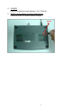
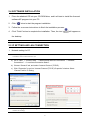
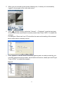
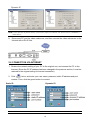
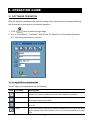
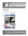
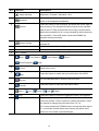
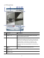
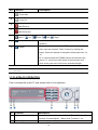
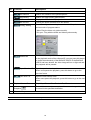
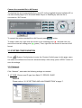
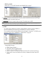
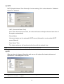
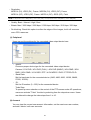
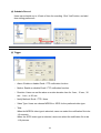
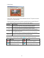
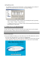
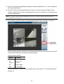
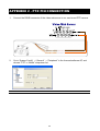
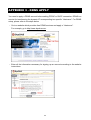
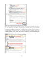
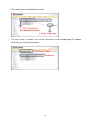
13
User Manual
Please read the instructions thoroughly before operation and retain this manual for future reference.
733_Manual_V1.1
IMPORTANT SAFEGUARD
CAUTION
RISK OF ELECTRIC SHOCK
CAUTION:
To reduce the risk of electric shock, do not expose this apparatus to rain or moisture.
Only operate this apparatus from the type of power source indicated on the label.
The company shall not be liable for any damages arising out of any improper use, even if we have
been advised of the possibility of such damages.
The lightning flash with arrowhead symbol, within an equilateral triangle, is
intended to alert the user to the presence of uninsulated “dangerous voltage”
within the product’s enclosure that may be of sufficient magnitude to
constitute a risk of electric shock to persons.
This exclamation point within an equilateral triangle is intended to alert the
user to the presence of important operating and maintenance (servicing)
instructions in the literature accompanying the appliance.
CE Mark
This apparatus is manufactured to comply with the radio interference.
The company does not warrant that this manual will be uninterrupted or
error-free. We reserve the right to revise or remove any content in this manual
at any time.
Firmware
BootLoader: 0.1.0.0
Kernel: 0.1.2.9
HtmlFile: 0.1.2.2
Mpeg4: 0.1.0.5
Application: 0.1.3.4
TABLE OF CONTENTS
1. PARTS AND FEATURES ---------------------------------------------------------------------------1.1 OVERVIEW ---------------------------------------------------------------------------------------1.2 FEATURES----------------------------------------------------------------------------------------1.3 SPECIFICATION ---------------------------------------------------------------------------------1.4 PACKAGE CONTENT --------------------------------------------------------------------------1.5 PANEL -----------------------------------------------------------------------------------------------
1
1
1
2
3
3
2. INSTALLATION AND CONNECTION ------------------------------------------------------------ 5
2.1 SYSTEM CONNECTION ----------------------------------------------------------------------- 5
2.2 APPLICATION DIAGRAM ---------------------------------------------------------------------- 5
2.3 CONNECTION CONFIGURATION----------------------------------------------------------- 6
2.4 SOFTWARE INSTALLATION ------------------------------------------------------------------ 7
2.5 IP SETTING AND LAN CONNECTION ----------------------------------------------------- 7
2.6 CONNECTION VIA INTERNET -------------------------------------------------------------- 10
3. OPERATION GUIDE --------------------------------------------------------------------------------- 11
3.1 SOFTWARE OPERATION -------------------------------------------------------------------- 11
3.1.1 Login AP Icon Explanation-------------------------------------------------------------- 11
3.1.2 Basic Operation --------------------------------------------------------------------------- 12
3.2 PLAYBACK OPERATION---------------------------------------------------------------------- 15
3.3 SYSTEM CONFIGURATION------------------------------------------------------------------ 17
3.3.1 Network-------------------------------------------------------------------------------------- 17
(1) DDNS ------------------------------------------------------------------------------------ 18
(2) SNTP ------------------------------------------------------------------------------------- 19
(3) FTP --------------------------------------------------------------------------------------- 19
(4) Mail --------------------------------------------------------------------------------------- 20
3.3.2 General -------------------------------------------------------------------------------------- 20
(1) Peripheral ------------------------------------------------------------------------------- 21
(2) Account ---------------------------------------------------------------------------------- 21
(3) File Path --------------------------------------------------------------------------------- 23
(4) Schedule Record ---------------------------------------------------------------------- 24
(5) Trigger------------------------------------------------------------------------------------ 24
3.3.3 Information---------------------------------------------------------------------------------- 26
(1) Log File ---------------------------------------------------------------------------------- 26
(2) Event Record List --------------------------------------------------------------------- 27
3.4 OPERATION VIA IE WEB BROWSER ----------------------------------------------------- 27
APPENDIX 1 - DVR PIN CONNECTION----------------------------------------------------------- 29
APPENDIX 2 - PTZ PIN CONNECTION ----------------------------------------------------------- 32
APPENDIX 3 - DDNS APPLY ------------------------------------------------------------------------- 33
1. PARTS AND FEATURES
1.1 OVERVIEW
With this video web server, you can monitor your security cameras over the Internet or LAN.
No PC is required. Just plug the camera and RJ45 networking cable to this device, and you
can monitor the live view through Internet or LAN with the licensed software AP or IE web
browser. MPEG-4 compression format makes the transmission faster for real-time video
stream.
1.2 FEATURES
Support MPEG4 compression format for real-time video stream
Compression format (MPEG4 / JPEG) is selectable for different network bandwidth and
applications
Support video / audio recording
Support alarm / motion-trigger recording
Adjustable motion detection sensitivity
Whenever alarm system triggered, video streaming or pictures will be uploaded over
FTP / email as an instant notification.
Support TCP/IP, PPPoE, DDNS and DHCP for network connection
Support DDNS and function as a router
Support NTSC system / PAL system / auto detection of video input signals
Support video access by AP (software) or HTML page (IE Explorer)
Full event record list for easy search and quick playback
Support schedule recording
Support multiple user access levels with security protection
Support multiple on-line users (up to 10 users)
Support watermark function
Support de-blocking and de-interlace functions
Support watch dog function for automatic network reconnection
ANR will reactivate recording function automatically when the network is reconnected
Easy to upgrade firmware
1
1.3 SPECIFICATION
MPEG-4 Video Web Server
Video Input
1 channel for analog & digital products,
1.0 Vp-p 75 composite, BNC
Audio Input
1 channel audio input
Alarm Input
2 inputs / 1 output
Watch dog
Yes
RS-485 Port
Yes
Ethernet (10/100 Base-T)
Network Interface
MPEG4 / JPEG
Image Compression
Video Adjustment
Network Connection
Brightness, Contrast, Saturation and Hue
Support TCP/IP, PPPoE, DDNS and DHCP for network
connection
Protocols
TCP/IP, ICMP, SMTP, FTP, HTTP, DHCP, DDNS, PPPoE, SNTP
Resolution
704x480, 352x240 (NTSC) / 704x576, 352x288 (PAL)
Performance
Video through put: Up to 30(NTSC), 25(PAL) frames/ second
Motion Trigger
Recording
Yes
Motion Detection
3 adjustable factors
Trigger & Action
Triggered by GPIO Input, Action: E-mail video/images or
video/images upload to FTP site's specific accounts
Watermark
Yes
De-blocking
Yes
De-interlace
Yes
Password protection
Security
Power Source
DC 12V
Current consumption
500 mA
* The specification is subject to change without notice.
2
1.4 PACKAGE CONTENT
Video Web
Server x 1
Licensed
Software AP x 1
Crossover LAN
cable x 1
Adapter x 1
DSUB
Connector x 1
User Manual &
Quick Start x 1
NOTE: Please check and make sure the above items are included in the sales package.
1.5 PANEL
The description for back panel connectors is as follows:
1. LAN
Connect the Video Web Server to the Internet or LAN with a cable, or connect directly to
PC with a standard pass-through cable.
2. VIDEO INPUT (1 channel)
Connect to a video source, such as the camera or DVR video output.
3. AUDIO INPUT (1 channel)
Connect to an audio source, such as the camera audio output.
4. ALARM I/O (optional for advanced applications)
Connect to control devices, such as the PTZ camera, DVR or external alarm signal
input.
3
5. POWER
Plug in the supplied power adaptor (12V / 500mA).
6. RESET (at the bottom of Video Web Server)
Press this button to restore default settings.
4
2. INSTALLATION AND CONNECTION
2.1 SYSTEM CONNECTION
1. Power
Connect to a DC 12V regulated adapter.
2. Video and Audio Input
Connect video and audio outputs of the camera or DVR…etc. Take DVR as an example,
after connection, set the baud rate and ID of the DVR. Make sure that the baud rate and
ID are the same as the settings of the video web server.
3. Software Installation
Install the software on PC.
4. IP Setting
Connect the video web server to your PC for IP setting (Local Connection).
5. LAN
After IP setting, connect the video web server to Internet with ADSL or CABLE MODEM.
6. ALARM I/O (Optional for advanced applications)
Connect to control devices, such as the PTZ camera, DVR or external alarm signal
input.
2.2 APPLICATION DIAGRAM
The diagram below illustrates the applications of the video web server.
5
2.3 CONNECTION CONFIGURATION
1. DVR Baud Rate and ID Setting
Set the baud rate and ID of the DVR. Make sure that the baud rate and ID are the same
as the settings of the video web server.
2. DVR and Video Web Server PIN Connection (Optional for advanced application)
Connect DVR PIN with VIDEO WEB SERVER PIN.
For detailed PIN connection, please refer to “APPENDIX 1 - DVR PIN CONNECTION”
and “APPENDIX 2 - PTZ PIN CONNECTION”
PIN
Function
Description
1, 6
RS485-A,
RS485-B
Use RS485-A & RS485-B serial communication signals to
control digital units just like that to control DVR.
4, 9
ALARM INPUT
Use PIN 4, 9 to receive the alarm input and then trigger
the video web server to send mails to users for auto
e-mail warning system.
5
GND
Ground
2, 3
NORMAL
Use PIN 2 or 3 to trigger the external device to act.
Please see the example above for 1CH/4CH DVR. It’s
recommended to solder these joints.
Attention: The voltage restriction is under DC24V 1A.
6
2.4 SOFTWARE INSTALLATION
1. Place the attached CD into your CD-ROM drive, and it will start to install the licensed
software AP program into your PC.
2. Click “
” twice to start the program installation.
3. Follow the on-screen instructions to finish the installation process.
4. Click “Finish” button to complete the installation. Then, the icon “
” will appear on
the desktop.
NOTE: After the physical connection, please go to the next two sections for IP address setting.
2.5 IP SETTING AND LAN CONNECTION
1. Network setting for PC.
NOTE: The following instructions are based on Windows XP O/S. If the O/S is Windows 2000, the setup procedure
is similar to that on Windows XP O/S.
a) Go to “Start” “Control Panel” “Network and Internet Connections” “Network
Connections” “Local Area Connection Status”.
b) Choose “General” tab, and select “Internet Protocol (TCP/IP).
c) Click “Properties” to go into “Internet Protocol (TCP/IP) Properties” window. Select
“General” tab for IP setting.
NOTE: Before changing the network setting, please write down the original values in case you may need to
restore the setting.
7
Click on “Use the following IP address”, and enter the IP address and subnet mask. The IP
address should be like 192.168.1.XXX, where XXX can be any number from 1 to 254
(except 10 because 192.168.1.10 is the default IP address of this video web server). The
subnet mask is always 255.255.255.0.
2. After PC network setting, connect your PC or notebook to the video web server with a
crossover LAN cable.
NOTE: In some operation environments, users might need the standard CAT5 cable.
3. To configure the server IP address, click “
” twice to enter the licensed software
AP login page.
4. Key in your user name, password, server IP address, and port number. Then, click the
green button to connect.
NOTE: By default, the user name and password are both “admin”, the server IP address is IP 192.168.1.10, and
the port number is 80.
8
5. When you see a similar screen as the following one, it means you’re successfully
logged in the program of the video web server.
6. Click “
” (System Config), and select “General” “Peripheral” to set the baud rate,
ID and model which users want to remotely control later. Press “APPLY” to enable the
changes.
The settings of “Baud rate” and “ID” should be the same as the setting of the external
device users want to remotely control.
7. Click “Network” to set the server IP address, gateway and net mask provided by your
local ISP (Internet service provider), as well as the web server, stream port and IP type.
Press “APPLY” to enable the changes.
Static IP
9
Dynamic IP
NOTE: For the dynamic IP (PPPoE, DHCP), users need to apply “Host Name” first. Please refer to “APPENDIX 3 DDNS APPLY”.
8. Disconnect PC and the video web server, and then connect the video web server to the
Internet with a RJ-45 line.
2.6 CONNECTION VIA INTERNET
1. Restore the network setting of your PC to the original one, and connect the PC to the
Internet. (Since the PC IP address has been changed in the previous section, it must be
restored to the original setting for Internet connection).
2. Click “
” twice, and enter your user name, password, static IP address and port
number. Then, click the green button to connect.
Static IP:
Dynamic IP:
NOTE: The default user name and password are both “admin”.
10
3. OPERATION GUIDE
3.1 SOFTWARE OPERATION
After the physical connection and network setting of the video web server, please following
the illustrations in this section for software operation.
1. Click “
” twice to enter the login page.
2. Key in “User Name”, “ Password”, and “Server IP” (Static IP) or “Host name”(Dynamic
IP). Click the green button to connect.
3.1.1 Login AP Icon Explanation
The AP login icon explanations are as following:
Icon
Function
Description
Address Book
Press this button to add a new IP address into the IP address book, or
choose any preset IP address to access the software AP software.
Search
Search available DVR IP addresses in the local area network and modify
the network setting of the DVR.
Player
Press this button to access and play the latest recorded file that is saved in
your PC.
Copy
Press this button to copy all the software installation files, so users can keep
all the settings of the video web server for next software installation on other
PCs.
11
Icon
Function
Description
Upgrade
Firmware
Press this button to upgrade DVR firmware or OSD language files. The
provided firmware and OSD files should be saved at PC first.
Login Setting
Users could press this button to set the transmission type (UDP or TCP) and
decode type (MPEG4 or JPEG).
NOTE: The version of the licensed software AP will be shown on the login page.
3.1.2 Basic Operation
DVR Control Panel
The illustration below takes 4CH DVR as an example.
NO.
Function
Description
a
Image transfer rate per second
b
Data transfer rate
c
Video only / Audio only / Both Video and Audio
d
Connect / Disconnect
Press to connect to / disconnect from the DVR.
12
NO.
Function
Description
e
Image adjusting
f
Brightness / Contrast / Saturation / Hue
Press this button to take a snapshot of the image which will be
Snapshot
saved in the designated destination.
g
Press this button to start recording, and press this button again to
Record
stop recording. The recorded files will be saved to the specified
path on the PC. Each recorded file can be up to 18,000 frames.
When the recorded file is full, a new-recorded file will be saved as
the second file. If the HDD space is less than 200MB, the
program will stop recording.
h
Press this button to enter the setting page of the licensed
System Config
software AP.
i
Number of online users
Show the current online user(s).
j
CH 1 ~ 4
Press to switch to a single channel you want to see.
k
PIP/+, QUAD/-
l
Stop /
Fast Rewind /
Slow Playback /
m
Fast Forward /
Pause /
Play
Digital zoom in/out
Zoom
n
Press this button to enable the key lock function of the DVR.
Lock
o
Record
The recorded data will be saved in the DVR HDD.
Search
Press this button to enter the DVR search menu.
p
q
Menu /
Up /
Down /
Left /
Right
r
Enter
Press this button to confirm the settings or enter your selection.
s
TURBO
To speed up menu selection or PTZ camera control at AP side,
users can activate "Turbo" function by clicking this button. Users
are allowed to change the turbo steps from 1 to 10.
Ex. If users activate the TURBO function and set the turbo step to
"3", one-mouse click will be as three-mouse click when users
press one of the button up/down/left/right.
13
PTZ Control Panel
NO. Function
a~i
j
Description
The same as DVR control panel.
Preset 1 ~ 16
A preset position is a pre-defined camera view that can
quickly and easily been viewed.
k
AUTO
Press this button to enter the auto pan or sequence mode
(depend on the setting in the PTZ menu). In the auto pan
mode, the Live View page will rotate through the selected
preset positions, in a set order or in sequence. In the
sequence mode, the Live View page will automatically
display the view from preset positions in a set order at set
intervals.
l
Pan
Press to enable/disable the panning function.
m
Zoom Tele
n
Zoom Wide
14
NO. Function
Description
o
Focus Near
p
Focus Far
q
Max Zoom In
r
Max Zoom Out
s
Menu /
t
Up /
Enter
Down /
Left /
Right
Press this button to confirm the settings or enter your
selection.
u
TURBO
To speed up menu selection or PTZ camera control at AP
side, users can activate "Turbo" function by clicking this
button. Users are allowed to change the turbo steps from 1 to
10.
Ex. If users activate the TURBO function and set the turbo
step to "3", one-mouse click will be as three-mouse click
when users press one of the button up/down/left/right.
NOTE: For Hot Point function, users can control our own brand PTZ camera screen to a specific point by moving
the cursor.
3.2 PLAYBACK OPERATION
Find a recorded file in the PC, and double click on it for playback.
NO.
Function
Description
a
Playback Information
Display the information, such as “Date”, “Time”, “Resolution”,
“Rewind / Forward Speed”, “Status” and “Functions”, etc.
b
Time Progress Bar
Show the playback progress status.
15
NO.
Function
c
Functions:
Description
De-interlace
Reduce the vibration of the paused picture.
De-blocking
Reduce the video mosaic phenomenon.
OSD
Display the OSD of the AP playback window.
AVI convert
Convert the entire recorded file to AVI format.
Config. Setting
Enter AP configuration setting box, and set the file path, text color,
and text color of progress status.
* Mute: Play the video only (without audio).
* AV sync.: Play with the audio and video synchronously.
Watermark
Proof the authenticity of the backup video.
In the playback mode of the software AP, you can press this button
to check the authenticity of the BACKUP VIDEO. If the BACKUP
VIDEO had been altered, the video image will turn to light red and
the playback will be paused.
Open Previous File
Open the previous backup video.
When users pause the playback, press this button to go to the
previous frame.
Open Next File
d
Playback Control Buttons
Play / Stop / Pause / Fast Rewind / Fast Forward
Snapshot
Press this button to take a snapshot of the current image which will
be saved in the specified destination.
e
f
Open the next backup video.
When users pause the playback, press this button to go to the next
frame.
Close the Player
Note: When users use remote AP manual recording, the watermark function is not supported.
16
Convert the recorded file to AVI format
The backup file can be played directly in your PC via the supplied licensed software AP, or
via other media players (Ex: Windows Media Player or RealPlayer) after the file is
converted to “AVI” format.
To convert the entire recorded file to AVI format, press
button.
To snap a video clip, right-click the mouse to set a starting point (▲ red) and click one
more time to set an ending point (▲ green). Then, right-click the mouse to convert to AVI
format.
3.3 SYSTEM CONFIGURATION
Press “
” (System Config) button to enter the “System Config” page. In this page, users
can select the different functions for advanced setup. After setup, press “APPLY” button to
save the settings.
3.3.1 Network
Click “Network”, and make the following settings as needed.
1) IP TYPE: Choose one IP type from Static IP / PPPOE / DHCP.
‧ Static IP
Please refer to “2.5 IP SETTING AND LAN CONNECTION” at page 7.
17
‧ PPPOE and DHCP
Please refer to “2.5 IP SETTING AND LAN CONNECTION” at page 7.
2) Web Port: The port to send commends. The port number should be the same as the DVR port
number. The default value is 80.
3) Stream Port: The port to transmit video and audio. The default value is 9000.
NOTE: If the video web server is connected to a router, always turn on both TCP and UDP services for the web port and
stream port on the router for the video web server to function normally.
(1) DDNS
You need to apply a DDNS account before setting PPPOE or DHCP connection. DDNS is a
service for transforming the dynamic IP corresponding to a specific “Hostname”.
Go to a website which provide free DDNS services and apply a “Hostname”. For DDNS service
application, please refer to “APPENDIX 3 - DDNS APPLY” at page 33.
‧ Enable DDNS Function:
a.
b.
c.
d.
e.
DDNS: Choose “Enable”.
User Name: Type your DDNS account.
Password: Type your DDNS password.
Domain: Type the “Host Name” you applied previously (EX: hostname.dyndns.org).
System Name: Choose the DDNS server where you applied the domain name (EX:
dyndns).
18
(2) SNTP
SNTP (Simple Network Time Protocol) is for time setting. So it is also related to “Schedule
Record” in “General”.
‧ GMT (Greenwich Mean Time)
Once users choose the time zone, the video web server will adjust the local area time of
the system automatically.
‧ Server Name
Users can simply use the automatic SNTP server (Automatic), or set another SNTP
server (Manual).
‧ Sync Server Time
The video web server will synchronize the time with the network time.
NOTE: This product does not have RTC, so it needs to get time from the Internet.
(3) FTP
When an alarm is triggered, the video web server will capture the instant pictures and
upload them to the assigned FTP site.
NOTE: To get an alarm notification at the FTP site when an alarm is triggered, users must enable the function of FTP
notification in “General” “Trigger”.
19
(4) Mail
When an alarm is triggered, the video web server will capture and email the instant pictures
(10 JPEG pictures max) or MPEG-4 film (3 seconds max) to the assigned recipients.
NOTE: To get an alarm mail when a motion is triggered, users must enable the function of Email notification in
“General” “Trigger”.
‧ SMTP Server: Enter the SMTP server address provided from your e-mail system
supplier.
‧ Mail from: Enter the entire mail address to ensure mails will not be blocked by some
SMTP servers. Users can add the email addresses in “Modify alarm email address”.
‧ Verify Password: If the mail server requires password verification, enter the user name
and password.
3.3.2 General
Users can set video-related settings here.
‧ Video System: NTSC / PAL / AUTO
‧ Video Type: MPEG4 (Only) / MPEG4 / JPEG
20
‧ Resolution:
MPEG 4 (D1), JPEG (D1), Frame / MPEG4 (D1), JPEG (CIF), Frame
MPEG 4 (CIF), JPEG (CIF), Frame / MPEG 4 (CIF), JPEG (CIF), Field
NOTE: D1 represents 704 x 480 (NTSC) / 704 x 576 (PAL); CIF represents 352 x 240 (NTSC) / 352 x 288 (PAL)
‧ Quality: Basic / Normal / High / Best
‧ Bitrate: Max / 3000 kbps / 2000 kbps / 1000 kbps / 640 kbps / 512 kbps / 256 kbps
‧ De-blocking: Check this option to soften the edges of the images, but it will consume
more CPU resources.
(1) Peripheral
Users can set the settings for the connected video output device here.
‧ Model:
Choose a proper device type for the connected video output device:
Camera / 1CH DVR / 4CH DVR (FULL) / 4CH DVR (BASIC) / 4CH DMR / 9CH
DMR / 16CH DMR / 4 CH DQR / PTZ / 4 CH MPEG 2 DVR / PTZ PELCO D.
‧ Baud Rate:
Set the baud rate for the connected device (2400, 4800, 9600, 19200, 38400,
57600, 115200).
‧ ID:
Set the ID number (0 ~ 255) for the connected device.
Turbo Step:
To speed up menu selection or the control of the PTZ camera under AP operations,
users can activate "Turbo" function by selecting from the drop-down menu. Users
are allowed to change the turbo steps from 1 to 10.
(2) Account
You can view the current user account information, set the maximum user number,
and add / delete / edit user accounts.
21
‧ To set the maximum user number, key in the number from 1 ~ 10 in “Max User(s)”.
‧ To create a new account, press “ADD”, and you will see the setting window as the
following:
Item
Description
Username
Set a user name what will be used at AP login page.
Password
Set a password what will be used at AP login page.
Life time
Select how long this account is allowed to stay online (1 Min / 5 Min / 10
Min / 1 Hour / 1 Day / INFINITY).
User level
Set the security level of an account. Each level has different
permissions for the following functions:
a
b
c d
e
f
‧ SUPERVISOR – Control all the functions.
‧ HIGH – Control all the functions except “c” & “f”.
‧ NORMAL – Control only “b”, “d” and “e” functions.
‧ GUEST – Only “b” function can be used. This level is only allowed
to watch the live view.
For the function description, please refer to the section “3.1.2 Basic
Operation” at page 12.
To confirm account creation, press “APPLY”; to discard the creation, press “EXIT”.
NOTE: If the number of current accounts already reaches the maximum number, you will not be able to create
an account unless any account is removed.
22
‧ To edit an account, select one current account you want to modify, and press
“EDIT”. You will see the following screen:
Modify the setting you want to change. To confirm the modification, press “OK”; to
discard the modification, press “EXIT”.
‧ To delete an account, select one current account you want to remove, and press
“DELETE”. The selected account will be removed and this operation cannot be
recovered.
(3) File Path
Users can view and change the file path for saving snapshots and recorded data here.
‧ Record Path: Assign the route for recorded files.
‧ Snapshot Path: Assign the route for snapshot images.
23
(4) Schedule Record
Users can schedule up to 10 sets of time for recording. Click “Add” button, and add
time setting preference.
NOTE: The time of the schedule record is based on the PC time, not the time in the video web server.
(5) Trigger
‧ Alarm: Enable or disable Email / FTP notification function.
‧ Motion: Enable or disable Email / FTP notification function.
‧ Duration: Users can set the alarm or motion duration time for 3 sec., 15 sec., 30
sec., 1 min., or 30 min.
‧ Notify Method: Email / FTP / None.
‧ Video Type: Users can choose MPEG4 or JPEG for the preferred video type.
‧ Total:
When the MPEG4 video type is selected, users can select the notification file to be
1-3 seconds.
When the JPEG video type is selected, users can select the notification file to be
1-10 pictures.
24
‧ Motion Setup:
‧ Motion Area: Users can set the motion detection area here. The pink area means
the area is not under detection.
‧ Motion Sensitivity: Users can set detection sensitivity factors manually (Manual),
or by choosing different level (Lower, Low, Normal, High, Higher).
Parameter
Description
NS
Motion detection sensitivity (using motion estimation algorithm).
The smaller the value, the more sensitive the detection will be.
LS
”LS” is to set the sensitivity of comparing two different images.
The smaller the value is, the higher the sensitivity for motion detection.
SS
”SS” is to set the sensitivity for detecting the size of one object (the number
of the grids) on the screen.
The smaller the value is, the higher the sensitivity for motion detection.
SENSITIVITY
Users can choose different sensitivity level of motion detection, or choose
“Manual” to manually set the value of sensitivity factors.
Trigger Refresh: Clean the alarm message “
Icon
(red)
Meaning
” which is shown on the screen.
Icon
An alarm event is triggered.
(red)
After alarm duration, the red alarm
(blue)
message will turn to blue.
A motion event is triggered.
After motion duration, the red
(blue)
25
Meaning
motion message will turn to blue.
3.3.3 Information
Users can view the information for all the online users here (Name/ IP Address / Level /
Media Type).
To update the online user information, press “Info Refresh” button.
(1) Log File
Users can view all the log information here.
‧ To show all the log information, press “Server Log” button. You can filter log types
you want to see by checking or unchecking the log types on the right side.
‧ To clear all the log information, press “Erase” button.
‧ To set the maximum log items to be seen here, enter a number from 1 ~ 2047 in
“MAX” LOG LIST”.
26
(2) Event Record List
It’s a database, which precisely lists all alarm- / motion-triggered events, with the IP
address of the video web server, event time, and number of frames.
‧ Users can directly play / delete / clear all event recording with ease by pressing
“Play” / “Delete” / “Delete” / “Clear All” button.
‧ To update the record list, click “Refresh” button. All the recorded files will be listed
systematically for easy search.
3.4 OPERATION VIA IE WEB BROWSER
You can view the images or control the connected video output device over the network
with IE web browser. Please install the licensed software AP first.
Note: The supported PC operation systems are Windows 2000 and Windows XP.
Follow the steps below:
1) Key in the IP address used by your video web server in the URL address box, such as
60.121.46.236, and press Enter. You will see the following page.
If the port number used by your video web server is NOT 80, you need to key in the port
number additionally. The format is IP address:port num, such as 60.121.46.236:888.
27
2) Check if you already installed the supplied licensed software AP. If no, click “Download
AP” and install the AP.
3) Enter the user name and password, the same as the ones used at AP login. Press
“Submit” when the user name and password are correct, or “Reset” to re-enter the user
name and password.
NOTE: For the stable network with high bandwidth, choose “TCP”; for the unstable network with lower
bandwidth, choose “UDP”.
4) You will see a similar screen as the following when the login information is correct.
All the buttons and their functions on the control panel are the same as the ones on AP
control panel except for the buttons indicated above.
Image Position Setting:
Button
Position
LT
LD
Center
RT
RD
Upper Left
Lower Left
Center
Upper Right
Lower Right
For the information of other buttons, please refer to the section “3.1.2 Basic Operation”
at page 12.
28
APPENDIX 1 - DVR PIN CONNECTION
1. Connect the DSUB connector supplied with the video web server to the DVR.
NOTE: For detailed DVR PIN description, please refer to your DVR user manual.
29
PIN CONFIGURATION
4CH DVR
8CH / 9CH / 16CH DVR
PIN
FUNCTION
PIN
FUNCTION
1
RS232-TX
1
GND
2
RS232-RX
2~9
ALARM INPUT
3~6
ALARM INPUT
10
PIN OFF
7
EXTERNAL ALARM NC
11
TXD232
8
EXTERNAL ALARM NO
12
RS485-A
9
GBD
13
EXTERNAL ALARM NO
10
RS485-B
14
PIN OFF
11
RS485-A
15 ~ 22
ALARM INPUT
12 ~ 13
PIN OFF
23
RXD232
14
ALARM RESET
24
RS485-B
15
EXTERNAL ALARM COM
25
EXTERNAL ALARM COM
2. Go to “MENU” “ADVANCE” “SYSTEM” in your DVR, and set the following items
(take 4CH DVR as an example):
SERIAL TYPE: RS-485
BAUD RATE: selectable, but need to be the same as the “Baud Rate” setting in
“System Config” “General” “Peripheral” of the licensed software AP.
HOST ID: selectable, but need to be the same as the “ID” setting in “System
Config” “General” “Peripheral” of the licensed software AP.
ADVANCE
SYSTEM
CAMERA
SERIAL TYPE
RS-485
DETECTION
BAUD RATE
02400
DISPLAY
HOST ID
001
ALERT
PASSWORD
SETUP
REMOTE
RESET DEFAULT
RESET
SYSTEM
CLEAR HDD
EXT 003
NETWORK
UPGRADE
NO
BACKUP
AUTO KEYLOCK
NEVER
HDD INFO
LANGUAGE
ENGLISH
EVENT LOG
VERSION
1088-10-K2-04-AA-11
VIDEO FORMAT
NTSC
30
3. Go to “General” “Peripheral” in “System Config” of the video web server. Be sure the
“Baud Rate” and “ID” settings are the same as those in your DVR.
31
APPENDIX 2 - PTZ PIN CONNECTION
1.
Connect the DSUB connector of the video web server to our own brand PTZ camera.
2.
Go to “System Config” “General” “Peripheral” in the licensed software AP, and
choose “PTZ” in “Model” drop-down list.
NOTE: Set the ID as the PTZ ID value. The default value is “0”.
32
APPENDIX 3 - DDNS APPLY
You need to apply a DDNS account before setting PPPoE or DHCP connection. DDNS is a
service for transforming the dynamic IP corresponding to a specific “Hostname”. For DDNS
setup, please refer to the steps below.
‧ Go to a website which provides free DDNS services and apply a “Hostname”.
For example, go to http://www.dyndns.com.
‧ Enter all the information necessary for signing up an account according to the website
instructions.
33
‧ Then, you will see the screen “Account Created”, and Dyndns will email the instructions
to your specified E-mail address for enabling your account. You must complete the
procedure according to the instructions in the mail. That is to must visit the confirmation
address within 48 hours of the time that the e-mail was sent to complete the account
creation process. Then, you will see “Account Confirmed”. Your account is created
successfully now.
34
‧ Log in with your account information and click ”My Service”.
‧ Click ”Add Host Services”.
‧ Click ”Add Dynamic DNS Host”.
35
‧ Fill in and choose the desired host name.
‧ The host name is created. You will be connected to the corresponding IP address
whenever you enter this hostname.
36