1
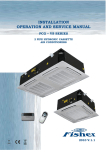
INSTALLATION OPERATION AND SERVICE MANUAL PCG – PS SERIES 4 PIPE HYDRONIC CASSETTE AIR CONDITIONERS 2010 V.1.0 INVESTING IN QUALITY, RELIABILITY & PERFORMANCE. ISO 9001 QUALITY Every product is manufactured to meet the stringent requirements of the internationally recognized ISO 9001 standard for quality assurance in design, development and production. CE SAFETY STANDARDS All products conform to the Certificate Europe directives (Machinery Safety, Electromagnetic Compatibility and Low Voltage), as required throughout the European Community, to guarantee correct standards of safety. WEEE MARK All products conform to the “weee” directive to guarantee correct standards of environmental solutions. ALWAYS MAKE SURE THAT THIS MANUAL REMAINS WITH THE PCG-VS WATER CASSETTE. READ THIS MANUAL BEFORE PERFORMING ANY OPERATION ON THE PCG-VS WATER CASSETTE. World Leading Design and Technology Equipped with the latest CAD/CAM computer aided design and manufacturing technology, our factories in China and Thailand produce over 2,000,000 air conditioning units each year, all conforming to the highest international standards of quality and safety. The Highest Standards of Manufacturing In order to guarantee the very highest standards and performance, we manage every stage in the manufacturing of our products. Throughout the production process we maintain strict control, originating with our extensive resources in research and development through to the design and manufacture of almost every individual component, from molded plastics to the assembly of units and controllers. Quality Controlled from Start to Finish Our highly trained staff and strict quality control methods enable us to produce products with an exceptional reputation for reliability and efficiency, maintained over many years. As well as full CE certification and ISO 9001, several products have UL/CSA (NRTL) safety approval plus ARI Certification in the USA, ROHS compliance for Europe, giving you the confidence of knowing our company is the right choice when selecting air conditioning equipment. HYDRONIC CASSETTE 3 INDEX PCG-PS SERIES 4 PIPE HYDRONIC CASSETTES A. B. C. D. E. F. G. H. I. J. K. L. M. N. CASSETTE MODEL ASSIGNMENTS SPECIFICATIONS a) COIL DATA b) COOLING CAPACITY TABLES c) ETHYLENE GLYCOL SOLUTIONS d) HEATING CAPACITY TABLE INSTALLATION MANUAL SAFETY CONSIDERATIONS OPERATING LIMITS BEFORE INSTALLATION SELECT LOCATION INSTALLATION LOCATION INSTALLATION METHOD OPENING DIMENSIONS AND POSITIONS FOR SUSPENSION BOLTS DRAIN PIPE WORK WATER CONNECTIONS VALVE CONFIGURATION EXTERNAL DRAIN PAN FRESH AIR RENEWAL CONNECTION BRANCH DUCT CONNECTION INTERCONNECTING WIRING CONTROL BOX CONFIGURATION MOUNTING FRONT PANEL ASSEMBLY FILTER REMOVAL MAINTENANCE HOW TO ACCESS AIR VENT AND WATER PURGE HOW TO CONNECT NON-DEFAULT FAN SPEED HOW TO FIX THE MOTOR AND FAN BLOWER HOW TO FIX CONDENSATE PUMP AND INTERNAL VALVE HOW TO FIX CONTROL BOX HOW TO INSTALL ELECTRIC HEATER EXPLODED DRAWINGS WITH PARTS DESCRIPTIONS DIMENSIONAL DRAWINGS VALVE INFORMATION REMOTE CONTROL HANDSET WIRED WALL PAD CONTROL CONTROLS SPECIFICATION WITH MASTER-SLAVE CONTROL SENSOR RESISTANCE R-T CONVERSION TABLE CONTROL AND POWER SUPPLY WIRING DIAGRAM MASTER-SLAVE CONTROL WIRING DIAGRAM TROUBLE SHOOTING APPENDIX I – MASTER SLAVE COMMUNICATION SETTING PAGE 4 5-6 7 7-9 10 11-13 14-36 14 14 15 15 16 17 18-20 21 21 21-22 23 23-24 24-25 26 27 28 28 29 30 30-31 32 33 34 35-36 37-38 39-41 42-43 44-45 46-49 50-57 58-59 60 61 62 63-65 4 HYDRONIC CASSETTE CASSETTE MODEL ASSIGNMENTS PCG- 06 - P S S 230V/1PH/50HZ P CHILLED/HOT WATER, 4-PIPE 06 08 09 12 16 PCG NOMINAL NOMINAL NOMINAL NOMINAL NOMINAL 3.24 3.60 4.15 5.10 5.90 KW KW KW KW KW HYDRONIC CASSETTE G SERIES 5 HYDRONIC CASSETTE PCG – PS (4-PIPE) SERIES 3-SPEED SPECIFICATIONS Model Number Of Fan Blowers H M Total flow Cooling Capacity* L 3 m /hr PCG-09 PCG-12 Single Twin Twin PCG-16 Twin 750 846 1098 1296 1650 648 540 924 1176 1300 588 410 858 1098 1100 H 3.24 3.60 4.15 5.10 5.90 2.86 3.02 3.23 4.70 4.80 2.60 2.42 3.06 3.95 3.65 2.75 2.94 3.82 4.40 4.93 2.48 2.60 3.16 4.04 4.31 2.33 2.22 2.98 3.54 3.56 L kW M Heating Capacity ** PCG-08 Single M H Sensible Cooling Capacity PCG-06 L kW H 4.14 4.43 6.67 7.20 7.90 M 3.84 4.00 5.85 6.60 6.95 L Noise Level @ 1 M (H/M/L) Power Supply kW 3.64 3.41 5.57 5.95 5.96 dB(A) 43/41/35 46/43/35 40/38/32 43/42/36 48/44/38 (V/Ph/Hz) 230/1/50 Fan Motor Power W 58 60 62 116 124 Fan Motor Running Current A 0.24 0.32 0.34 0.48 0.64 Fan Motor Starting Current A 0.76 0.89 0.88 1.52 1.77 L/h 580 Operation Control & Thermostat Remote Control Handset & Wired Wall Pad Cooling Water Flow Rate 636 733 901 1043 Heating Water Flow Rate L/h 354 380 571 617 677 Cooling Water Pressure Drop kPa 12.0 14.7 27.8 22.4 29.0 Heating Water Pressure Drop kPa 3.0 3.5 8.7 10.1 12.0 L 1.07 1.07 1.36 1.91 1.90 L 0.49 0.49 0.86 0.86 0.86 Cooling Water Content Heating Water Content Cond. Drain Connection I.D. Dimensions mm(in) L mm 585 585 1140 1140 1140 W mm 585 585 580 580 580 H mm 290 290 250 290 290 Panel Dimensions (L x W x H) mm Gross Weight Kg Connection Method Water Connection 19.05(3/4) 680×680×28 33 680x1240x28 33 52 59 59 Socket (Threaded Female) In mm(in) 19.05(3/4) Out mm(in) 19.05(3/4) * Cooling : 27C db/19C wb entering air temperature,7C entering water and 12C leaving water temperature with water flow rates as above. **Heating : 20C db entering air temperature ,70C entering water temperature and 60C leaving water temperature. 6 HYDRONIC CASSETTE PCG – PS (4-PIPE) SERIES 5-SPEED SPECIFICATIONS PCG-06 PCG-08 PCG-09 PCG-12 Single Single Twin Twin Twin 710 846 1080 1350 1650 648 708 738 1236 1350 600 648 600 1140 1236 2 450 600 500 852 1140 1 350 450 400 650 852 5 3.02 3.60 4.24 5.00 5.98 2.86 3.02 2.78 4.75 5.00 2.60 2.86 2.32 3.98 4.75 1.98 2.60 2.00 3.22 3.98 Model Number Of Fan Blowers 5 4 Total flow 3 3 M /hr 4 Cooling Capacity* 3 kW 2 Sensible Cooling Capacity 1 1.72 1.98 1.62 2.65 3.22 5 2.60 2.94 3.73 4.27 4.85 4 2.48 2.60 2.72 4.04 4.27 2.33 2.48 2.27 3.58 4.04 1.82 2.33 1.95 2.82 3.58 3 kW 2 Heating Capacity ** PCG-16 1 1.56 1.82 1.58 2.32 2.82 5 4.00 4.43 6.67 6.98 7.91 4 3.84 4.00 5.27 6.60 6.98 3 kW 3.63 3.84 4.63 5.92 6.60 2 2.79 3.63 4.11 5.10 5.92 1 2.05 2.79 3.58 4.20 5.10 44/40/38/32/30 46/44/40/38/32 39/35/33/31/28 45/41/39/33/31 47/45/41/39/33 Noise Level @ 1 M (H/M/L) dB(A) Power Supply (V/Ph/Hz) 230/1/50 Fan Motor Power W 58 66 100 116 132 Fan Motor Running Current A 0.26 0.29 0.44 0.52 0.58 Fan Motor Starting Current A 0.77 0.88 1.33 1.54 1.77 Cooling Water Flow Rate L/h 533 636 749 883 1057 Heating Water Flow Rate L/h 342 380 571 598 678 Cooling Water Pressure Drop kPa 10.7 14.7 28.8 20.9 29.0 Heating Water Pressure Drop kPa 3.0 3.5 13.0 15.0 17.5 L 1.07 1.07 1.36 1.91 1.91 L 0.49 0.49 0.86 0.86 0.86 1140 Operation Control & Thermostat Cooling Water Content Heating Water Content Cond. Drain Connection I.D. Remote Control Handset & Wired Wall Pad mm(in) Dimensions L mm 585 585 1140 1140 W mm 585 585 580 580 580 H mm 290 290 250 290 290 33 52 Panel Dimensions (L x W x H) mm Gross Weight Kg Connection Method Water Connection 19.05(3/4) 680×680×28 33 680x1240x28 59 59 Socket (Threaded Female) In mm(in) 19.05(3/4) Out mm(in) 19.05(3/4) * Cooling : 27C db/19C wb entering air temperature,7C entering water and 12C leaving water temperature with water flow rates as above. **Heating : 20C db entering air temperature ,70C entering water temperature and 60C leaving water temperature. 7 HYDRONIC CASSETTE COIL DATA - COOLING Fin Height Model (mm) PCG-06-08-PS PCG-09-PS PCG-12-16-PS 250 200 250 1176 2148 2148 COIL DATA - HEATING Fin Height Model (mm) PCG-06-08-PS PCG-09-PS PCG-12-16-PS Fin Length (mm.) Inner Outer 250 200 250 Fins per inch No. of rows No. of circuits Tube Diameter 13 13 13 2 2 2 3 3 5 3/8” 3/8” 3/8” Fins per inch No. of rows No. of circuits Tube Diameter 13 13 13 1 1 1 3 3 3 3/8” 3/8” 3/8” 1277 2286 2286 Fin Length (mm.) Inner Outer 1176 2148 2148 1277 2286 2286 COOLING CAPACITY TABLES PCG-06-PS TAI DB24℃-WB17.4℃ TAI DB27℃-WB19℃ TAI DB27℃-WB19.5℃ TAI DB28℃-WB21 Twi qa Pf Pfs Tad Taw dPw Qw Pf Pfs Tad Taw dPw Qw Pf Pfs Tad Taw dPw Qw Pf Pfs Tad Taw dPw Qw °C m3/h kW kW °C °C kPa l/h kW kW °C °C kPa l/h kW kW °C °C kPa l/h kW kW °C °C kPa l/h 750 3.3 2.52 13.8 12.5 12.1 583 4.45 3.08 14.5 12.6 20.7 786 4.85 3 14.6 12.6 24 857 5.9 3.14 15.2 12.9 34.3 1043 648 2.87 2.28 13.2 12.4 9.45 507 3.86 2.79 13.8 12.5 16.1 682 4.2 2.74 14 12.5 18.6 742 5.1 2.85 14.4 12.8 26.4 901 588 2.66 2.14 12.9 12.3 8.2 470 3.56 2.63 13.3 12.4 14 630 3.88 2.58 13.6 12.4 16.1 685 4.7 2.68 14 12.7 22.7 830 750 2.75 2.33 14.55 13.35 8.93 486 3.865 2.915 15.15 13.5 16.35 683 4.225 2.83 15.35 13.55 19 746.5 5.28 2.965 15.9 13.85 28.35 933 648 2.405 2.09 14.1 13.25 6.985 425 3.36 2.635 14.5 13.4 12.74 593.5 3.7 2.585 14.7 13.4 15 653.5 4.57 2.69 15.15 13.75 21.85 807.5 588 2.24 1.96 13.8 13.1 6.15 395. 3.08 2.48 14.05 13.35 15.95 545 3.395 2.435 14.3 13.35 12.85 599.5 4.215 2.53 14.75 13.65 18.8 744.5 750 2.2 2.14 15.3 14.2 5.76 389 3.24 2.75 15.8 14.4 12 580 3.6 2.66 16.1 14.5 14 636 4.66 2.79 16.6 14.8 22.4 823 648 1.94 1.9 15 14.1 4.52 343 2.86 2.48 15.2 14.3 9.37 505 3.2 2.43 15.4 14.3 11.4 565 4.04 2.53 15.9 14.7 17.3 714 588 1.82 1.79 14.7 14 4.1 321 2.6 2.33 14.8 14.3 7.9 460 2.91 2.29 15 14.3 9.6 514 3.73 2.38 15.5 14.6 14.9 659 750 1.86 1.81 16.6 14.7 4.18 328. 2.8 2.51 16.7 15.1 9.1 495 3.09 2.5 16.7 15.2 10.8 546 4.13 2.62 17.2 15.5 18.2 729. 648 1.62 1.55 16.4 14.6 3.21 286. 2.45 2.24 16.3 15 7.18 432. 2.73 2.28 16.1 15.1 8.75 482. 3.59 2.38 16.6 15.4 14.2 635 588 1.5 1.47 16.3 14.6 2.8 264 2.25 2.09 16 14.9 6.1 398 2.51 2.14 15.7 15.0 7.5 443. 3.32 2.23 16.2 15.3 12.2 587. 750 1.52 1.48 17.9 15.2 2.6 268 2.32 2.27 17.7 15.8 6.2 410 2.58 2.34 17.4 16 7.7 456 3.6 2.45 17.9 16.3 14.1 636 648 1.3 1.27 17.9 15.2 1.9 230 2.04 2 17.4 15.7 5 360 2.26 2.13 16.8 15.9 6.1 400 3.15 2.23 17.3 16.2 11.1 556 588 1.18 1.15 17.9 15.2 1.5 208 1.91 1.86 17.2 15.6 4.2 337 2.11 1.99 16.5 15.8 5.4 373 2.92 2.09 17 16.1 9.6 516 5 6 7 8 9 TAI: Twi: Qw: Dpw: Qa: Air in temperature Fluid in temperature Fluid flow rate in heat exchanger Pressure drop standard coil Air flow Pf: Pfs: Tad: Taw: Total cooling capacity Sensible cooling capacity Discharge air dry bulb temperature Discharge air wet bulb temperature Note: Design and specification are subject to change without prior notice for product improvement. 8 HYDRONIC CASSETTE PCG-08-PS TAI DB24℃-WB17.4℃ TAI DB27℃-WB19℃ TAI DB27℃-WB19.5℃ TAI DB28℃-WB21 Twi qa Pf Pfs Tad Taw dPw Qw Pf Pfs Tad Taw dPw Qw Pf Pfs Tad Taw dPw Qw Pf Pfs Tad Taw dPw Qw °C m3/h kW kW °C °C kPa l/h kW kW °C °C kPa l/h kW kW °C °C kPa l/h kW kW °C °C kPa l/h 846 3.7 2.69 14.3 12.5 15.4 654 4.92 3.29 15.1 12.7 25.6 870 5.45 3.28 15.3 12.7 31.1 963 6.62 3.35 15.8 12.9 43.8 1170 700 3.1 2.4 13.5 12.4 11.3 548 4.1 2.93 14.1 12.6 18.5 724 4.45 2.89 14.2 12.6 21.5 786 5.5 3 14.7 12.8 31.5 972 550 2.48 2.05 12.6 12.3 7.5 438 3.27 2.5 13 12.5 12.3 578 3.56 2.48 13.1 12.5 14.4 630 4.78 2.66 14.2 12.6 24.5 845 846 3.05 2.52 14.9 13.4 11.2 538 4.26 3.12 15.7 13.6 20.15 753 4.72 3.10 15.85 13.65 24.4 833 5.92 3.18 16.4 13.85 36.25 1046 700 2.57 2.19 14.4 13.3 8.15 453 3.56 2.77 14.8 13.5 14.6 628.5 3.89 2.74 14.9 13.55 17.15 687 4.93 2.84 15.4 13.75 550 2.06 1.83 13.8 13.2 5.4 364 2.85 2.36 13.75 13.4 9.75 502.5 3.14 2.34 13.85 13.4 11.65 554.5 4.15 2.485 14.6 13.55 19.35 846 2.39 2.34 15.5 14.3 7 422 3.6 2.94 16.3 14.5 14.7 636 3.98 2.91 16.4 14.6 17.7 703 5.22 3.01 17 14.8 28.7 922 700 2.03 1.98 15.3 14.2 5 358 3.02 2.60 15.5 14.4 10.7 533 3.33 2.58 15.6 14.5 12.8 588 4.36 2.68 16.1 14.7 20.7 770 550 1.64 1.6 15 14.1 3.3 290 2.42 2.22 14.5 14.3 7.2 427 2.71 2.2 14.6 14.3 8.9 479 3.52 2.31 15 14.5 14.2 622 846 2.015 1.965 16.85 14.8 5.05 356 3.06 2.7 17.15 15.2 2.755 16.95 15.45 13.15 585.5 4.55 2.825 17.65 15.65 22.75 804 700 1.685 1.64 16.75 14.75 3.75 297 2.575 2.34 16.6 15.1 8 454.5 2.785 2.38 16.45 15.35 9.45 491.5 3.8 2.51 16.8 15.55 16.4 671 550 1.35 1.315 16.6 14.7 2.3 238.5 2.075 1.96 15.95 15 5.35 366.5 2.3 2.02 15.95 15.25 6.6 406.5 3.065 2.16 15.8 15.4 11.22 541.5 846 1.64 1.59 18.2 15.3 3.1 290 2.52 2.46 18 15.9 7.4 445 2.65 2.6 17.5 16.3 8.6 468 3.88 2.64 18.3 16.5 16.8 686 700 1.34 1.3 18.2 15.3 2.5 236 2.13 2.08 17.7 15.8 5.3 376 2.24 2.18 17.3 16.2 6.1 395 3.24 2.34 17.5 16.4 12.1 572 550 1.06 1.03 18.2 15.3 1.3 187 1.73 1.7 17.4 15.7 3.5 306 1.89 1.84 17.3 16.2 4.3 334 2.61 2.01 16.6 16.3 8.23 461 Pf: Pfs: Tad: Taw: Total cooling capacity Sensible cooling capacity Discharge air dry bulb temperature Discharge air wet bulb temperature 5 6 7 8 9 TAI: Twi: Qw: Dpw: Qa: Air in temperature Fluid in temperature Fluid flow rate in heat exchanger Pressure drop standard coil Air flow 11.05 540.5 3.315 26.1 871 733.5 Note: Design and specification are subject to change without prior notice for product improvement. PCG-09-PS TAI DB24℃-WB17.4℃ TAI DB27℃-WB19℃ TAI DB27℃-WB19.5℃ TAI DB28℃-WB21 Twi qa Pf Pfs Tad Taw dPw Qw Pf Pfs Tad Taw dPw Qw Pf Pfs Tad Taw dPw Qw Pf Pfs Tad Taw dPw Qw °C m3/h kW kW °C °C kPa l/h kW kW °C °C kPa l/h kW kW °C °C kPa l/h kW kW °C °C kPa l/h 1098 4.5 3.21 15.4 13.5 32 795 5.9 4.08 16.1 13.5 52.3 1043 6.3 4 16.1 13.6 58.9 1113 8.03 4.16 16.6 13.7 91.3 1419 924 3.51 2.8 14.2 13.4 20.7 620 4.56 3.51 14.7 13.4 32.7 806 5.03 3.48 14.8 13.4 39.3 889 6.34 3.65 15.2 13.6 59.7 1120 858 3.3 2.63 14 13.3 18.4 583 4.26 3.33 14.3 13.3 29.2 753 4.63 3.31 14.4 13.4 34 818 5.89 3.46 14.8 13.5 52.4 1041 1098 3.68 3.005 16.1 14.15 22.75 650 5.07 3.905 16.75 14.4 40.55 896 5.44 3.79 16.75 14.5 46.15 961 7.105 3.915 17.3 14.65 74 1255.5 924 2.835 2.45 15.4 14.05 14.55 500.5 3.91 3.305 15.4 14.25 25.2 691 4.295 3.275 15.5 14.35 30.25 759.5 5.585 3.435 15.9 14.55 48.2 986.5 858 2.675 2.315 15.15 13.95 13.04 472.5 3.655 3.135 15 14.15 22.5 646 3.945 3.115 15.1 14.35 26.1 697 5.2 3.235 15.6 14.45 42.25 919 1098 2.86 2.8 16.8 14.8 13.5 505 4.15 3.82 17.4 15.3 27.8 733 4.58 3.58 17.4 15.4 33.4 809 6.18 3.67 18 15.6 56.7 1092 924 2.16 2.1 16.6 14.7 8.4 381 3.23 3.16 16.1 15.1 17.7 576 3.56 3.07 16.2 15.3 21.2 630 4.83 3.22 16.6 15.5 36.7 853 16.4 15.4 32.1 5 6 7 8 9 TAI: Twi: Qw: Dpw: Qa: 858 2.05 2 16.3 14.6 7.68 362 3.06 2.98 15.7 15 15.8 539 3.26 2.92 15.8 15.3 18.2 576 4.51 3.01 1098 2.72 2.63 17.1 15.1 12.7 480.5 4 3.47 17.9 15.45 26.1 706.5 4.41 3.36 17.95 15.55 31.25 779.5 5.99 3.445 18.55 15.75 53.75 924 2.06 1.995 16.95 15.05 7.75 363.5 3.095 2.925 16.7 15.3 16.25 547 3.43 2.885 16.8 15.45 19.8 606.5 4.715 3.025 17.3 858 1.925 1.87 16.8 15 6.59 340 2.905 2.78 16.3 15.2 14.6 513.5 3.18 2.755 16.4 15.4 17.4 562 4.405 2.855 17 15.55 30.9 778.5 1098 2.58 2.46 17.4 15.4 11.9 456 3.76 3.21 18.4 15.6 23.4 664 4.24 3.14 18.5 15.7 29.1 750 5.8 3.22 19.1 15.9 50.8 1025 924 1.96 1.89 17.3 15.4 7.1 346 2.93 2.75 17.3 15.5 14.8 518 3.3 2.7 17.4 15.6 18.4 583 4.6 2.83 18 15.8 33.4 813 858 1.8 1.74 17.3 15.4 5.5 318 2.76 2.62 16.9 15.4 13.4 488 3.1 2.59 17 15.5 16.6 548 4.3 2.7 17.6 15.7 29.7 760 Pf: Pfs: Tad: Taw: Total cooling capacity Sensible cooling capacity Discharge air dry bulb temperature Discharge air wet bulb temperature Air in temperature Fluid in temperature Fluid flow rate in heat exchanger Pressure drop standard coil Air flow Note: Design and specification are subject to change without prior notice for product improvement. 15.65 35.05 797 1058.5 833 9 HYDRONIC CASSETTE PCG-12-PS TAI DB24℃-WB17.4℃ TAI DB27℃-WB19℃ TAI DB27℃-WB19.5℃ TAI DB28℃-WB21 Twi qa Pf Pfs Tad Taw dPw Qw Pf Pfs Tad Taw dPw Qw Pf Pfs Tad Taw dPw Qw Pf Pfs Tad Taw dPw Qw °C m3/h kW kW °C °C kPa l/h kW kW °C °C kPa l/h kW kW °C °C kPa l/h kW kW °C °C kPa l/h 1296 5.25 4.08 15.2 13.3 23.7 928 7.42 5.04 16.1 13.4 44.2 1311 8.05 4.94 16.3 13.5 50.9 1423 10 5.05 17 13.8 74.4 1767 1171 4.5 3.7 14.5 13.2 18 795 6.43 4.58 15.4 13.3 34.2 1136 7 4.52 15.6 13.4 39.7 1237 8.7 4.64 16.1 13.6 58.4 1538 1098 3.81 3.29 13.8 13.1 13.4 673 5.32 4.06 14.4 13.2 24.3 940 5.75 3.98 14.6 13.3 27.7 1016 7.25 4.19 15 13.5 42.3 1281 1296 4.615 3.785 15.9 13.85 18.75 815.5 6.435 4.76 16.85 14.25 34.35 1137 6.805 4.64 16.75 14.4 38.45 17.5 14.7 60.4 1559.5 5 6 7 8 9 TAI: Twi: Qw: Dpw: Qa: 1171 4 3.44 15.3 13.75 14.5 706.5 5.59 4.31 16.2 4.25 16.2 14.3 30.7 1061 7.7 4.395 16.75 14.55 47.5 1361 1098 3.355 3.035 14.6 13.65 10.63 592.5 4.59 3.785 15.25 14.05 18.7 811 4.975 3.755 15.3 14.2 21.75 879 6.41 3.92 15.8 14.45 34.1 1132.5 1296 3.98 3.49 16.6 14.4 13.8 703 5.10 4.48 17.6 15.1 22.4 901 5.56 4.34 17.2 15.3 26 982 7.65 4.54 18 15.6 46.4 1352 1171 3.5 3.18 16.1 14.3 11 618 4.70 4.04 17 15 19.1 839 5.01 3.98 16.8 15.2 21.7 885 6.7 4.15 17.4 15.5 36.6 1184 1098 2.9 2.78 15.4 14.2 7.86 512 3.95 3.54 16.1 14.9 13.1 682 4.2 3.53 16 15.1 15.8 742 5.57 3.65 16.6 15.4 25.9 984 1296 3.49 3.19 17.15 14.75 11.2 616.5 5.175 4.075 18.3 15.25 22.65 914.5 5.395 4.02 18.05 15.5 24.7 953 7.455 4.195 18.75 15.75 44.5 1317.5 1171 3.095 2.895 16.75 14.65 9 547 4.525 3.71 17.7 15.15 17.85 799.5 4.79 3.685 17.55 15.4 20.1 846 6.5 34.8 1148.5 1098 2.535 2.44 16.4 14.6 6.43 447.5 3.71 3.25 16.85 15.05 12.45 4.01 3.275 16.75 15.3 14.6 708.5 5.42 3.4 17.35 15.55 24.9 957.5 1296 3 2.89 17.7 15.1 8.6 530 4.9 3.67 19 15.4 20.8 866 5.23 3.7 18.9 15.7 23.4 924 7.26 3.85 19.5 15.9 42.6 1283 1171 2.69 2.61 17.4 15 7 476 4.3 3.38 18.4 15.3 16.6 760 4.57 3.39 18.3 15.6 18.5 807 6.3 3.52 18.9 15.8 33 1113 1098 2.17 2.1 17.4 15 5 383 3.56 2.99 17.6 15.2 11.8 630 3.82 3.02 17.5 15.5 13.4 675 5.27 3.15 18.1 15.7 23.9 931 Pf: Pfs: Tad: Taw: Total cooling capacity Sensible cooling capacity Discharge air dry bulb temperature Discharge air wet bulb temperature Air in temperature Fluid in temperature Fluid flow rate in heat exchanger Pressure drop standard coil Air flow 14.15 26.65 987.5 6.005 1202.5 8.825 4.795 656 3.835 18.15 15.65 Note: Design and specification are subject to change without prior notice for product improvement. PCG-16-PS TAI DB24℃-WB17.4℃ TAI DB27℃-WB19℃ TAI DB27℃-WB19.5℃ TAI DB28℃-WB21 Twi qa Pf Pfs Tad Taw dPw Qw Pf Pfs Tad Taw dPw Qw Pf Pfs Tad Taw dPw Qw Pf Pfs Tad Taw dPw Qw °C m3/h kW kW °C °C kPa l/h kW kW °C °C kPa l/h kW kW °C °C kPa l/h kW kW °C °C kPa l/h 1650 6 4.4 15.5 13.2 28.9 1060 8.4 5.5 16.5 13.4 53.3 1484 9 5.4 16.7 13.6 60.1 1591 11.5 5.59 17.3 13.7 93.8 2032 1300 5 3.89 14.8 13.1 20.9 884 6.4 4.83 15.6 13.3 37.4 1220 7.4 4.73 15.7 13.4 42.3 1308 9.3 4.89 16.3 13.6 63.5 1644 1100 3.8 3.24 13.7 13 12.7 671 5.32 4.03 14.3 13.1 23.4 940 5.7 3.96 14.4 13.2 26.4 1007 7.17 4.13 14.9 13.4 39.8 1267 1650 5.15 4.14 16.2 13.9 22.45 910 7.19 5.175 17.2 14.3 41.1 1271 7.75 5.105 17.2 14.45 46.75 1370 10.15 5.26 17.85 14.6 75.7 1793.5 1300 4.3 3.645 15.55 13.8 16.25 760 5.7 4.55 16.4 14.2 29.15 1052 6.35 4.45 16.3 14.3 32.7 1122 8.265 4.625 16.9 14.5 52.05 1461 1100 3.37 3.04 14.65 13.65 10.4 595.5 4.65 3.805 15.25 14 18.65 821.5 4.95 3.74 15.1 14.1 20.85 874.5 6.385 3.89 15.6 14.3 32.7 1128.5 1650 4.3 3.88 16.9 14.6 16 760 5.90 4.93 17.9 15.2 29.0 1043 6.5 4.81 17.7 15.3 33.4 1149 8.8 4.93 18.4 15.5 57.6 1555 1300 3.6 3.4 16.3 14.5 11.6 636 4.80 4.31 17.2 15.1 20.9 883 5.3 4.17 16.9 15.2 23.1 936 7.23 4.36 17.5 15.4 40.6 1278 1100 2.94 2.84 15.6 14.3 8.1 520 3.65 3.56 16.2 14.9 13.9 703 4.2 3.52 15.8 15 15.3 742 5.6 3.65 16.3 15.2 25.6 1650 3.85 3.55 17.35 14.85 13.2 680.5 5.61 4.495 18.45 15.4 25.85 991.5 6.15 4.425 18.45 15.55 30.35 1087 8.45 4.55 19.15 15.75 53.75 1300 3.155 3.025 16.95 14.8 9.15 558 4.65 3.935 17.75 15.3 18.45 821.5 5.025 3.87 17.65 15.45 21.1 888 6.915 4.015 1100 2.545 2.475 16.6 14.7 6.1 450 3.45 3.315 16.75 15.15 1650 3.4 3.22 17.8 15.1 10.4 601 5.24 4.14 19 1300 2.71 2.65 17.6 15.1 6.7 480 4.3 3.6 1100 2.15 2.11 17.6 15.1 4.1 380 3.34 3.05 5 6 7 8 9 TAI: Twi: Qw: Dpw: Qa: Air in temperature Fluid in temperature Fluid flow rate in heat exchanger Pressure drop standard coil Air flow 18.3 15.65 990 1493.5 37.5 1222 12 646.5 3.97 3.26 16.6 15.25 13.85 701.5 5.4 3.395 17.15 15.45 24.05 954.5 15.6 22.8 926 5.8 4.04 19.2 15.8 27.3 1025 8.1 4.17 19.9 16 49.9 1432 18.3 15.5 16 760 4.75 3.57 18.4 15.7 19.1 840 6.6 3.67 19.1 15.9 34.4 1166 17.3 15.4 10.1 590 3.74 3 17.4 15.5 12.4 661 5.2 3.14 18 15.7 22.5 919 Pf: Pfs: Tad: Taw: Total cooling capacity Sensible cooling capacity Discharge air dry bulb temperature Discharge air wet bulb temperature Note: Design and specification are subject to change without prior notice for product improvement. 10 HYDRONIC CASSETTE ETHYLENE GLYCOL SOLUTIONS Adding Ethylene Glycol to the water system so as to multiply the performance figures by the values given in the following table. Freezing point (℃) 0 -5 -10 -15 -20 -25 35% 0.97 1.11 1.22 40% 0.965 1.14 1.24 Percentage of ethylene glycol in weight cPf cQ cdp 0 1 1 1 12% 0.985 1.02 1.07 20% 0.98 1.04 1.11 cPf: correction factor cooling capacity cQ: correction factor flow rate cdp: correction factor pressure drop 28% 0.974 1.075 1.18 11 HYDRONIC CASSETTE HEATING CAPACITY TABLES TAI 18℃ PCG-06-PS TAI 20℃ TAI 22℃ TAI 24℃ Twi Two qa Pf Tad Qw dPw Pf Tad Qw dPw Pf Tad Qw dPw Pf Tad Qw dPw °C °C m3/h kW °C l/h kPa kW °C l/h kPa kW °C l/h kPa kW °C l/h kPa 750 2.28 27.4 390 2.36 2.07 28.5 354 1.98 1.86 29.6 318 1.64 1.65 30.7 282 1.3 648 2.12 28 363 2.1 1.92 29.1 329 1.74 1.73 30.2 296 1.44 1.54 31.3 263 1.14 588 2 28.4 342.8 1.86 1.82 29.5 312 1.6 1.64 30.5 281 1.31 1.46 31.5 250 1.02 750 2.24 27.2 192 0.6 2.04 28.4 175 0.557 1.83 29.5 166.9 0.457 1.62 30.6 158.8 0.357 648 2.07 27.8 177 0.57 1.9 29 162 0.491 1.71 30.1 146.6 0.406 1.52 31.2 131.2 0.321 588 1.98 28.3 170 0.53 1.8 29.4 154 0.445 1.61 30.4 138 0.362 1.42 31.4 122 0.279 750 4.37 36 374.6 2.2 4.14 37 354 1.98 3.91 38.1 335 1.78 3.68 39.2 316 1.58 648 4.05 37.2 347 1.91 3.84 38.2 329 1.74 3.64 39.3 312 1.58 3.44 40.4 295 1.42 588 3.83 38 328 1.73 3.63 39 311 1.56 3.46 40.1 296.6 1.44 3.29 41.2 282.2 1.32 45 40 50 40 70 60 TAI: Twi: Qw: Dpw: Qa: Air in temperature Fluid in temperature Fluid flow rate in heat exchanger Pressure drop standard coil Air flow Pf: Tad: Total heating capacity Discharge air temperature Note: Design and specification are subject to change without prior notice for product improvement. TAI 18℃ PCG-08-PS Twi Two qa °C °C m3/h kW 846 2.45 700 2.22 550 45 40 50 40 70 60 TAI: Twi: Qw: Dpw: Qa: Pf Tad TAI 20℃ Qw dPw Pf Tad °C l/h 26.9 420 kPa kW 2.7 2.21 27.8 380 2.3 1.93 28.8 330 846 2.4 26.7 700 2.16 550 1.89 846 TAI 22℃ Qw dPw °C l/h kPa kW 28 378.9 2.23 1.99 2 28.8 342.9 1.9 1.8 1.76 1.75 29.8 300 1.47 205 0.8 2.18 27.9 186.9 0.7 27.5 185 0.6 1.96 28.6 168 28.6 162 0.5 1.73 29.7 148 4.68 34.9 401 2.5 4.43 36.1 380 700 4.22 36.5 361 2.1 4 37.6 550 3.7 38.7 317 1.63 3.41 41 Air in temperature Fluid in temperature Fluid flow rate in heat exchanger Pressure drop standard coil Air flow Pf: Tad: Pf Tad TAI 24℃ Qw dPw Qw dPw °C l/h kPa kW 29.2 341 1.85 1.77 °C l/h kPa 30.4 303.1 1.47 29.9 308 1.55 1.6 31 273.1 1.2 1.58 30.8 270 1.23 1.41 31.8 240 0.99 1.96 29.1 168 0.6 1.74 30.3 149.1 0.5 0.52 1.74 30.2 0.414 1.55 30.7 149 0.42 1.52 31.8 130 0.32 132 0.4 1.37 31.7 116 0.386 2.3 4.2 37.2 360 2.04 3.97 38.3 340 1.78 343 1.9 3.73 39.7 319 1.65 3.46 41.8 295 1.4 292 1.4 3.32 40.6 284 1.33 3.23 40.2 276 1.26 Total heating capacity Discharge air temperature Note: Design and specification are subject to change without prior notice for product improvement. Pf Tad 12 HYDRONIC CASSETTE TAI 18℃ PCG-09-PS Twi Two qa °C °C m3/h kW 1098 4.22 924 3.78 858 45 40 50 40 70 60 TAI: Twi: Qw: Dpw: Qa: Pf Tad TAI 20℃ Qw dPw Pf °C l/h kPa kW 29.8 723.4 15.3 3.86 30.9 648 12.6 3.42 3.56 31.4 610 11.2 1098 4.36 30.2 373.7 924 3.88 31.2 332.6 858 3.69 31.8 1098 7.61 924 Qw dPw 858 dPw °C l/h kPa kW 30.8 661.7 13.1 3.47 °C l/h kPa kW 31.7 594 10.7 3.08 31.7 586.2 10.4 3.09 32.6 530 8.7 2.76 3.25 32.2 557 9.54 2.95 33 505 8.1 2.65 4.7 3.98 31.1 341 3.8 3.54 32.2 303 3.95 3.6 32.1 308.6 3.3 3.2 3.21 33 275 2.67 316.3 3.5 3.38 32.6 289.7 2.95 3.06 33.5 262 2.46 40.7 671.3 14.3 6.67 41.5 571 13 6.27 42.4 551 7.01 42.6 602.1 11.5 5.85 43.5 546.3 10.5 5.55 44.4 6.46 43 558.6 10.2 5.57 44.3 537 9.5 5.27 44.9 Pf: Tad: Pf Tad TAI 24℃ Qw Air in temperature Fluid in temperature Fluid flow rate in heat exchanger Pressure drop standard coil Air flow Tad TAI 22℃ Pf Tad Qw dPw °C l/h kPa 32.6 526.3 8.3 33.5 473.8 7 33.8 453 6.66 3.22 33.1 276.2 2.65 2.88 33.8 247 2.14 2.74 34.4 234.3 1.97 11.8 6.08 43.3 522 10.6 537 9.53 5.82 45.3 507.7 8.56 528 8.5 5.61 45.5 467 7.5 Total heating capacity Discharge air temperature Note: Design and specification are subject to change without prior notice for product improvement. TAI 18℃ PCG-12-PS Twi Two qa °C °C m3/h kW 1296 4.54 1176 4.17 1098 3.68 1296 4.67 28.1 400 1176 4.3 28.8 368 1098 3.8 30 325.7 1296 8.07 36.8 1176 7.55 1098 6.85 45 40 50 40 70 60 TAI: Twi: Qw: Dpw: Qa: Pf Tad TAI 20℃ Qw dPw Qw dPw °C l/h kPa kW 27.8 778 17.4 4.13 °C l/h kPa kW 28.9 708 14.6 3.72 28.5 714.8 15 3.8 29.6 651 12.65 3.43 29.6 630.8 12 3.36 30.6 576 10.1 5.3 4.3 29.3 368.6 4.54 3.92 29.9 336 3.63 3.48 30.9 298 745 16.2 7.20 38 38.1 681 13.7 6.6 40.1 604 11 5.95 Air in temperature Fluid in temperature Fluid flow rate in heat exchanger Pressure drop standard coil Air flow Pf Tad TAI 22℃ Qw dPw °C l/h kPa kW 30.1 637 12.1 3.31 30.6 588 10.5 3.06 3.03 31.5 519 8.4 2.7 4.6 3.88 30.4 332 3.8 3.8 3.57 31 306 3.24 3.1 3.15 31.9 270 2.58 710 14.8 6.87 39 674 39 651 12.6 6.25 40.1 41 576 10.1 5.65 42.1 Pf: Tad: Pf Tad TAI 24℃ Qw dPw °C l/h kPa 31.3 566 9.6 31.6 525 8.35 32.4 462 6.7 3.46 31.5 295.4 3 3.22 32.1 276 2.68 2.82 32.9 242 2.06 13.5 6.45 40 638 12.2 621 11.6 5.95 41.2 591 10.6 548 9.3 5.68 43.2 520 8.5 Total heating capacity Discharge air temperature Note: Design and specification are subject to change without prior notice for product improvement. Pf Tad 13 HYDRONIC CASSETTE TAI 18℃ PCG-16-PS Twi Two qa °C °C 45 40 50 40 70 60 TAI: Twi: Qw: Dpw: Qa: Pf Tad m3/h kW 1650 4.96 1300 TAI 20℃ Tad Qw dPw dPw °C l/h kPa kW 27 850 20.3 4.57 °C l/h kPa kW 28.3 783 17.7 4.08 4.4 28 754 16.4 4.02 29.2 689 14 3.62 1100 3.75 29.4 642.8 12.3 3.43 30.5 588 10.6 3.1 1650 5.12 27.3 439 6.2 4.7 28.5 402 5.3 4.24 29.7 363 4.4 3.78 30.9 324 3.5 1300 4.54 28.3 389 5 4.14 29.5 354 4.2 3.75 30.6 321 3.54 3.36 31.7 288 2.88 1100 3.86 29.7 330 3.7 3.53 30.8 302.6 3.2 3.21 31.8 275 2.7 2.89 32.8 247.4 2.2 1650 8.51 35.3 755 18.9 7.90 36.5 677 17.5 7.33 37.7 620 15.9 7.07 38.9 601 14.3 1300 7.42 37.2 681 15.2 6.95 38.4 627 13.9 6.81 39.4 592 12.6 6.20 40.4 567 11.3 1100 6.50 39.6 617 11.5 5.96 40.8 582 10.3 6.25 41.7 557 9.52 5.82 42.6 532 8.74 Pf: Tad: Pf Tad TAI 24℃ Qw Air in temperature Fluid in temperature Fluid flow rate in heat exchanger Pressure drop standard coil Air flow Pf TAI 22℃ Qw dPw °C l/h kPa kW 29.4 700 14.3 3.59 30.3 620 11.6 3.22 31.6 531 8.8 2.77 Total heating capacity Discharge air temperature Note: Design and specification are subject to change without prior notice for product improvement. Pf Tad Qw dPw °C l/h kPa 30.5 617 10.9 31.4 551 9.2 32.7 474 7 14 HYDRONIC CASSETTE THE INSTALLATION MANUAL HOT & CHILLED WATER SYSTEM AIR CONDITIONERS First check the contents of the package. FACTORY SUPPLIED ACCESSORIES Check to ensure all factory supplied accessories are supplied with the unit. FACTORY SUPPLIED ACCESSORIES LCD Remote control Mounting Bracket (Already on the unit) Installation manual Batteries External drain pan AMOUNT 1 1 1 2 1 The appliance should be installed in accordance with national wiring regulation. SAFETY CONSIDERATIONS 1. When working on air conditioning equipment, observe precautions in this manual, and on plates and tables attached to the unit. Follow all safety codes and other safety precautions that may apply. 2. Installing and servicing air conditioning equipment should be done by trained and qualified service personnel only. Untrained personnel can perform only basic maintenance functions such as cleaning coils, filters and replacing filters. 3. Ensure that the electrical supply and frequency are adequate for the operating current required for this specific installation. WARNING - Before any service or maintenance operations turn off the main power switch. 1. The manufacturer denies any responsibility and warranty shall be void if these installation instructions are not observed. 2. Never switch off the power main supply when unit is operating in the cooling cycle. To switch off the fan coil unit use only the ON-OFF button. 3. This avoids over-flow in the drain pan, by allowing the pump to drain any condensate water due to regulating valve losses when chiller is working. OPERATING LIMITS 1. Power supply Volt 230 Phase 1 Hz 50 2. Water circuit Minimum entering water temperature: +2 °C Maximum entering water temperature: +80 °C Water side maximum pressure: 1400 kPa (142 m.w.c) HYDRONIC CASSETTE 15 BEFORE INSTALLATION The installation site must be established by the system designer or other qualified professional, taking account of the technical requisites and current standards and legislation. PCG fan coils must be installed by an authorized company only. PCG fan coils are designed for installation in a false ceiling, for intake of fresh air from outside and for deviation of a small part of the treated air for discharge in a neighboring room. They must be installed in such a way as to enable treated air to circulate throughout the room and in respect of the minimum distances required for technical maintenance operations. 1. It is advisable to place the unit close to the installation site without removing it from the packaging. 2. Do not put heavy tools or weights on the packaging. 3. Upon receipt, the unit and the packaging must be checked for damage sustained in transit and if necessary, a damage claim must be filed with the shipping company. 4. Check immediately for installation accessories inside the packaging. 5. Do not lift unit by the condensate drain discharge pipe or by the water connections; lift it by the four corners.(Fig.1) 6. Check and note the unit serial number. Fig.1 Fig.2 SELECT LOCATION 1. 2. 3. 4. 5. Do not install the unit in rooms where flammable gas or alkaline acid substances are present. Aluminum/copper coils and/or internal plastic components can be damaged irreparably. Do not install in workshops or kitchens; oil vapors drawn in by treated air might deposit on the coils and alter their performance or damage the internal plastic parts of the unit. Installation of the unit will be facilitated by using a stacker and inserting a plywood sheet between the unit and the elevated stacker.(Fig.2) It is recommended to position the unit as centrally as possible in the room to ensure optimum air distribution. (Fig.3) Generally the best louver position is the one which allows air diffusion along the ceiling. Alternatively intermediate positions can be selected. Check that it is possible to remove panels from ceiling in the selected position, to allow enough clearance for maintenance and servicing operations. Fig.3 16 HYDRONIC CASSETTE INSTALLATION LOCATION INSTALL THE UNIT IN A POSITION: 1. 2. 3. 4. Having sufficient strength to carry the weight of the unit. Where the inlet and outlet grilles are not obstructed and the conditioned air is able to blow all over the room. From where condensate can be easily run to drain. Check the distance between the upper slab and false ceiling to ensure the unit will suit the distance. See Fig.4 Fig.4 B A Model PCG-09 PCG-06/08/12/16 A (mm.) 250 290 Fig.5 5. Ensure there is sufficient space around the unit to service it. See Fig.5 B (mm.) 10 or more 10 or more HYDRONIC CASSETTE 17 INSTALLATION METHOD CASSETTE UNIT Using the installation template open ceiling panels and install the suspension bolts as in Fig.6 below 600 x 600: Dimensions for opening 632 x 280: Suspension Bolts MODELS PCG-06/08 600 x 1160: Dimensions for opening 750 x 632: Suspension Bolts MODELS PCG-09/12/16 FIG. 6 18 HYDRONIC CASSETTE OPENING DIMENSIONS AND POSITIONS FOR SUSPENSION BOLTS 1. 2. 3. 4. Mark position of suspension rods, water lines and condensate drain pipe, power supply cables and remote control cable. Supporting rods can be fixed, depending on the type of ceiling, as shown in Fig. 7 and Fig.8. Fit suspension brackets supplied with the unit to the threaded rods (Fig.9). Do not tighten nuts and counter nuts; this operation has to be done only after final leveling of the unit, when all the connections have been completed. Fig.7 Fig.8 Fig.9 5. 6. Ensure the ceiling is horizontally level, otherwise condensate water cannot drain. The casing is fixed to the slab with 4 drop rods. The rods should have two nuts and washers to lock the unit in position. The Cassette brackets will then hook over the washers. 7. When lifting the Cassette into position care should be taken not to lift the unit by the drip tray, which could be damaged. 8. Lift unit (without the air panel) with care by its four corners only. Do not lift unit by the condensate drain discharge pipe or by the piping connections. 9. Incline unit (Fig.10, Fig.11, Fig.13, Fig.14) and insert it into the false ceiling. Insert the rods into the bracket slot. With minimum height (see table) false ceilings, it might be necessary to remove some T brackets of the false ceiling temporarily. 10. Using a level guide, line up the unit with a spirit level, and keep dimension between the body and the lower part of the false ceiling (Fig.12 Fig.15). 11. Line up the unit to the supporting bars of the false ceiling tightening the nuts and counter nuts of the threaded rods. HYDRONIC CASSETTE 19 12. After connection of the condensate drain piping and piping connections, check again that the unit is level. Fig. 10 Fig. 11 Fig. 12 MODEL A (mm.) PCG-06/08 3 HYDRONIC CASSETTE 20 Fig. 13 Fig. 14 Fig. 15 MODEL A (mm.) PCG-09/12/16 3 13. The spaces between the unit and ceiling can now be adjusted. Use the drop rods to make the adjustment. 14. Check to ensure the unit is level. The drain will then automatically be lower than the rest of the drip tray. 15. Tighten the nuts on the suspended rods. HYDRONIC CASSETTE 21 DRAIN PIPE WORK INDOOR UNIT 1. 2. 3. 4. 5. The unit is fitted with a condensate pump with a 500 mm. lift. The unit is provided with 22 mm. bore flexible hose 300 mm. long. The flexible hose should be fitted into a 22 mm O/S Φ. polyvinyl tube and sealed. The drain must be installed with a downward slope. On completion the drain line should be insulated. Fig. 16 WATER CONNECTIONS The hydraulic connections of the PCG unit is 3/4” water connection with gaskets it is advisable to tighten the gaskets with a spanner. For piping dimensional drawing please refer to “DIMENSIONAL DRAWINGS” VALVE CONFIGURATION There are two types of valve configuration for PCG cassette: a) Internal integrated valve and b) external valve – a) Pre-installed 2-way and 3-way integrated valves (Fig. 17) Fig. 17 Model PCG-06/08 PCG-09/12/16 (please refer to “VALVE INFORMATION”) Integrated valve information Type inch 2-way & 3-way 1/2” 2-way & 3-way 3/4” 22 HYDRONIC CASSETTE b) External valves i. Replace integrated valve with plug-and-play replacement connector Fig. 18 Procedures: 1) Before connecting water supply to the PCG cassette. First remove the integrated valve using spanner 2) Replace with plug-and-play connector (Fig. 18) 3) Connect the external valve directly onto the cassette. ii. Disable integrated valve functionality using valve cap Procedures: 1) Remove integrated valve actuator by pressing on both sides. (Fig. 19) 2) Place the valve cap onto the valve body. (Fig. 20) 3) Connect the external valve directly onto the cassette. Fig. 19 Fig. 20 23 HYDRONIC CASSETTE EXTERNAL DRAIN PAN Procedures: Align the two (2) screw holes in the fixing plate to the two (2) holes in the external drain pan. (Fig. 21) Make sure the drain pan is horizontal. Tighten the two screws and making sure the external drain pan is installed flush with the fixing plate. (Fig. 22) When the installation is completed, it is necessary to wrap connecting pipe with insulation to prevent leakage to ceiling tile. Fig. 21 Fig. 22 FRESH AIR RENEWAL CONNECTION The fresh air system for PCG cassette allows up to 15% of unit airflow as fresh air intake (per connection). Maximum 2 fresh air connections per unit. 1. 2. 3. 3. The corners of the cassette allow separate ductwork to be installed for outside air intake (Fig.23) Cut and remove anti-condensate insulating material. Open the mounting plate (Fig. 24) Install the flanges to casing and fix it with 2 screws. Flange is rectangular duct with dimension 110 x 55mm. Fig. 23 24 HYDRONIC CASSETTE Fig. 24 Fig. 25 BRANCH DUCT CONNECTION The side opening allows separate ductwork to be installed for branch ducting. (Fig. 26) Cut and remove anti-condensate insulating material. Install your flanges and conduits to casing. Conduit can be flexible polyester with spring core or corrugated aluminium externally coated (dia.4 in.) with anti-condensate material (fiberglass 12-25 mm thickness). Order flanges (spigots) and blanking plates as accessories separately. BRANCH DUCT DIMENSION Fig. 26 HYDRONIC CASSETTE 1. Look for the yellow sticker on the casing for location of branch duct or fresh air intake connections. 2. The sticker is at the center of a knock out hole underneath the casing insulation. Use a cutter and follow along the pre-cut circular marking as shown and trim off the insulation. 3. Knock out the pre-cut hole. 4. Connect the flange on to the opening with Φ3 mm. x 12 mm. tapping screws. BRANCH DUCT INSTALLATION STICKER Step 1 Step 2 Step 3 Step 4 Tapping Screw Dia 3 mm.x12 mm.l. 25 26 HYDRONIC CASSETTE INTERCONNECTING WIRING We recommend that screened cable be used in electrically noisy areas. 1. Always separate low voltage (5VDC) signal wires from power line (230 VAC) to avoid electromagnetic disturbance of control system. 2. Do not install the unit where electromagnetic waves are directly radiated at the infra red receiver on the unit. 3. Install the unit and components as far away as is practical (at least 5 meters) from the electromagnetic wave source. 4. Where electromagnetic waves exist use shielded sensor cable. 5. Install a noise filter if any harmful noise exists in the power supply. Fig.27 Important note: Please ensure the cable of the main powers supply will be > 500mm long from the control box terminal block. This is to ensure the control box can be slide out easily during maintenance activities. Wiring procedures: 1) 2) 3) 4) 5) 6) 7) Open the terminal block cover by removing 4 screws Connect L & N cable to the terminal according to wiring diagram on page 63 Connect room temperature sensor, coil temperature sensors to the control box Connect stepping motor Connect receiver display Connect wall pad (optional) Slide in the control box to the unit casing and fixed with 2 screws. HYDRONIC CASSETTE 27 CONTORL BOX CONFIGURAITON a) Plug-and-play control box with full functionality PCB (please refer to wiring diagram on page 60) The PCB is a universal type with multiple configurations selectable using dipswitches. Please provide dip-switch setting according to below. There are 2 DIP Switch sets on the PCB, one with 8 Dip-switches which named as DIP-Switch A and one with 6 Dip-switches which named as DIP-Switch B For master-slave connection setting, please refer to Appendix I. DIP Switch A SW1-SW6 is used for master slave address setting. DIP switch address setting: 1 for ON, 0 for OFF. SW7 0 0 1 1 SW8 0 1 0 1 Model setting Cool-Heat Cool-Heat + booster heater Cooling only Cool + primary heater DIP Switch B is used for model configuration as follow:DIP switch setting: 1 for ON, 0 for OFF. SW1 PR-O contact setting 0 Economy contact 1 Window contact SW2 System setting 0 2 pipes system 1 4 pipes system SW3 Preheat setting 0 28C 1 36C SW4 MTV setting [applicable to 2 pipes system only] 0 Without motorized valve 1 With motorized valve SW5 Reserved SW6 RS485 termination setting 0 Other than below 1 Last unit on RS485 communication bus HYDRONIC CASSETTE 28 MOUNTING FRONT PANEL ASSEMBLY 1. 2. 3. Remove return grille from front panel. Move the front panel to casing. Tighten 4 screws as shown in Fig 28,29 Fig.28 FILTER REMOVAL 1. 2. 3. 4. Unlock the two fasteners on the front panel. Open the grille downward with care. Pull the filter out along the slot. Clean the filter and reassemble. PCG-06/08 PCG-09/12/16 Fig.29 HYDRONIC CASSETTE 29 PRELIMINARY CHECKS BEFORE START-UP 1. The unit should not be started up until the system piping has been cleaned and all the air has been purged. 2. Check condensate drain pipe slope. 3. After you have connected the main power supply to the cassette unit, it is necessary to check the good function of the condensate water pump which is installed inside. Due to transport vibration, it might be possible that the float switch is hung up and the pump might not work in the correct way. For this reason, you have to do the following, to ensure good functioning of the unit: 4. Install the cassette unit in an absolute horizontal position. 5. Fill the internal drain pan (manually) with enough water to ensure the drain pump is working. 6. You can fill the drain pan by pouring water through the external drain pan. If everything is correct, the water will be pushed out into the pipe work you have installed. If the valve does not open, you have to make sure the float switch is not hung up inside the unit and you will have to loosen it by hand. 7. 8. 9. Make sure that air filter is clean and properly installed. Ensure that voltage and current values correspond with the unit nameplate values; check electrical connections. Verify that air outlets are not closed. MAINTENANCE 1. Before performing any service or maintenance operations, turn off the main power switch. 2. The air filter is made of acrylic fiber and is washable in water. To remove filter simply open the intake grille by releasing the two catches. See Fig.19 and the section filter removal. 3. Check the filter periodically and before the operating season; clean or replace as necessary. PROLONGED UNIT SHUT-DOWN 1. Prior to restarting the unit: 2. Clean or replace the air filters. 3. Check and remove any obstruction from the external drain pan and the internal drain pan. EXTRA MAINTENANCE 1. The electrical panel is easily accessible by removing the cover panel. 2. The inspection or replacement of internal components such as; heat exchanger coil, condensate 3. Drain pump, float switch, involves the removal of the condensate drain pan. See Fig.20-25. 4. During the removal of the condensate drain pan protect the floor under the unit with a plastic sheet from condensate water that could be spilled. 5. Remove fixing screws of the drain pan fixture and remove condensate drain pan with care. The appliance is intended to be maintained by qualified service personnel and located at a height of not less than 2.5m. HYDRONIC CASSETTE 30 HOW TO ACCESS AIR VENT AND WATER PURGE 2nd STEP: release the air vent / water purge by loosen the screws. 1st STEP: remove the grill, air vent and water purge are located at the pointed area. HOW TO CONNECT NON-DEFAULT FAN SPEED 1st STEP: remove the grill. 3rd STEP: remove the finger guard and venturi 2nd STEP: remove the finger guard by removing 4 screws. 4th STEP: Fan speed terminal is located in the area inside the red rectangle. HYDRONIC CASSETTE 5th STEP: change the fan speed wiring according to below wiring diagram 31 HYDRONIC CASSETTE 32 HOW TO FIX THE MOTOR AND FAN BLOWER 1st STEP: remove the grill. 3rd STEP: remove the finger guard and Venturi 2nd STEP: remove the finger guard by removing 4 screws. 4th STEP: remove fan blower using a spanner 5th STEP: remove the motor by removing 4 bolts and disconnect fan motor wire connector. HYDRONIC CASSETTE 33 HOW TO FIX CONDENSATE PUMP AND INTERNAL VALVE 1st STEP: remove the grill. 3rd STEP: remove the front panel by disconnecting stepping motor and IR receiver. 5th STEP: remove the drain pan fixture and internal drain pan 2nd STEP: remove the front panel by removing 4 screws. 4th STEP: removing the drain pan fixture by removing 8 screws. 6th STEP: remove the drain pump or valve HYDRONIC CASSETTE 34 HOW TO FIX CONTROL BOX 1st STEP: remove the grill. 3rd STEP: remove the front panel by disconnecting stepping motor and IR receiver. 5th STEP: sliding out the control box. 2nd STEP: remove the front panel by removing 4 screws. 4th STEP: remove 2 screws on the control box. 6th STEP: Remove the terminal cover by removing 4 screws and unplug the wiring on the terminal. And replace with a new control box HYDRONIC CASSETTE 35 HOW TO INSTALL ELECTRIC HEATER 1st STEP: remove the grill. 3rd STEP: remove the front panel by disconnecting stepping motor and IR receiver. 5th STEP: remove internal drain pan fixture and internal drain pan 2nd STEP: remove the front panel by removing 4 screws. 4th STEP: remove the drain pan fixture by removing 8 screws. 6th STEP: slide in the insulated ring of the electric heater to the electric heater mounting shown above HYDRONIC CASSETTE 7th STEP: slide in the rest insulated rings of the electric heater to the electric heater mounting shown above 36 8th STEP: Plug in the electric heater wiring to the connector shown above. HYDRONIC CASSETTE 37 EXPLODED VIEW DRAWING PCG-06/08-PS 01---casing 02---3-way 4-ports valve (optional) G3/4 03---mounting brackets 04---fresh air flange (optional) 05---Condensate water pump 05-01---pump body 05-02---float switch 05-03---flexible hose 1 05-04---non-return valve 05-05--- flexible hose 2 05-06---drainage head 05-07---pump fixture 06--- coil 07---coil and EH’s fixture 08---control system 08-01---back of control box 08-02---front of control box 08-03---cover of control box 08-04---terminal block 08-05---main PCB 08-05-01---chilled water coil temperature sensor 08-05-02---hot water coil temperature sensor 08-05-03---room temperature sensor 09---motor with capacitor 10---electrical heater (optional) 11---fan blower 12---drain pan with 3mm insulation 13---drain pan fixture 14---finger guard 15---Venturi 16---returned air grill 17---filter 18---front panel 18-01---stepping motor (2-corotation) 18-02---stepping motor (2-reversion) 18-03---IR receiver 19---external drain pan 20--- remote handset and wired wall pad (optional) HYDRONIC CASSETTE 38 PCG-09/12/16-PS 01---casing 02---3-way 4-ports valve (optional) G3/4 03---mounting brackets 04---fresh air flange (optional) 05---Condensate water pump 05-01---pump body 05-02---float switch 05-03---flexible hose 1 05-04---non-return valve 05-05--- flexible hose 2 05-06---drainage head 05-07---pump fixture 06--- coil 07---coil and EH’s fixture 08---control system 08-01---back of control box 08-02---front of control box 08-03---cover of control box 08-04---terminal block 08-05---main PCB 08-05-01---chilled water coil temperature sensor 08-05-02---hot water coil temperature sensor 08-05-03---room temperature sensor 09---motor with capacitor 10---electrical heater (optional) 11---fan blower 12---drain pan with 3mm insulation 13---drain pan fixture 14---finger guard 15---Venturi 16---returned air grill 17---filter 18---front panel 18-01---stepping motor (2-corotation) 18-02---stepping motor (2-reversion) 18-03---IR receiver 19---external drain pan 20--- remote handset and wired wall pad (optional) HYDRONIC CASSETTE DIMENSIONAL DRAWINGS PCG-06-08-PS 39 HYDRONIC CASSETTE PCG-09-PS 40 HYDRONIC CASSETTE PCG-12/16-PS 41 HYDRONIC CASSETTE VALVE INFORMATION 42 HYDRONIC CASSETTE 43 HYDRONIC CASSETTE REMOTE CONTROL HANDSET WIRELESS LCD HANDSET DISPLAY 44 HYDRONIC CASSETTE ***When unit with handset is master, settings are automatically sent to slaves; ***Auto Cool-Heat operation will be applicable in 4-pipe system only. ***Swing is not applicable to PCG models. 45 HYDRONIC CASSETTE 46 ***Wall pad will recognize the main board model automatically whether it is 2 pipes or 4 pipes. Auto Cool-Heat operation will be applicable in 4 pipe system only. ***When the wall pad is connected to the main board, air sensor inside the wall pad will be automatically set as primary source and the return air sensor from the unit will be disabled. 47 HYDRONIC CASSETTE WALL PAD OPERATION 1) Clock display and setting System has an accurate internal real time clock used for time indication and timer ON/OFF function. TIME Real time clock display area indicates internal time clock which can be set by or TIME button. 2) Day display and setting The wall pad has day display function which is used for day indication and timer ON/OFF function. D AY Day display icon indicates current day. Press button to set day. 3) Timer ON/OFF setting If master unit is in global control mode and on/off timer setting is reached, master unit will command the whole network to be on or off. Otherwise timer on/off is effective to the local unit only. The system supports 7 days on/off timer setting. a) TIMER Press button once, and ON symbol blinking indicates on timer programming mode, day display area indicates the day for setting timer on. If on timer for this day is null, timer TIME display area shows , otherwise the on timer setting will be shown. Press button to change the on timer setting. Press CANCEL TIME key to cancel the current on timer selected . Press and the timer display area will show timer is to be programmed. or DA Y button to change the day the on TIMER b) Press button again, and OFF symbol blinking indicates off timer programming mode. The setting method is the same as on timer setting above. c) Press d) Should there be any on or off timer being programmed, will light up. Should there be any unexecuted on or off timer for the current day, its corresponding ON or OFF icon will light up. e) Hold down TIMER button again, to exit timer on/off setting function. CANCEL button for 3 seconds to cancel all timer settings. Timer set by master unit is as follows:1. Press NET button to enter into networking control mode. Unit area blinking indicates the TIME slave unit under control. Press will be skipped automatically. TIME or to select the desired slave unit. Units that are off TIMER DA Y button once to enter into on timer programming mode. Press button to 2. Press select the required day of the week. Master unit will then retrieve the setting from the selected slave unit and timer display area will show “rEAd”. The on timer setting will be TIME shown upon reading the data successfully. Press setting. or TIME button to change the on timer 48 HYDRONIC CASSETTE TIMER D AY 3. Press button again to enter into off timer programming mode. Press button to select the required day of the week. Master unit will then retrieve the setting from the selected slave unit and timer display area will show “rEAd”. The off timer setting will be TIME shown upon reading the data successfully. Press setting. or TIME button to change the off timer TIMER 4. Upon completion of changing timer settings for the selected day, press button again to exit timer programming mode. The settings will then upload to the selected slave unit. The next day of the week settings can be done only upon completion of sending data to the slave units. (Repeat steps 1~4 if setting is required for the next day of the week). 5. In Global control mode: CANCEL Pressing Master button for 3 seconds will cancel all timer settings in all slave units. Timer settings will be broadcast to all slave units. Clock synchronization by master unit is as follows: TIME and TIME buttons for 3 seconds to activate clock synchronization to all slave 1. Press units. Master wall pad will respond with a beeping sound. 4) Key lock In order to prevent unauthorized access to the system setting, a key lock function is provided to prevent mischief. Hold down and for 3 seconds to activate key lock, symbol lights up. Repeat the same to exit key lock. Only button is applicable in key lock mode. 5) Swing Press SWIN G to activate or deactivate swing function. 6) Sleep Press SLEEP button to activate or deactivate sleep setting. Sleep is valid in cool or heat modes only. 7) Temperature setting Press or to enter into temperature setting mode, temperature display area blinks indicating the current set temperature. Press the above buttons to adjust the set temperature. 8) Mode setting Press MODE button to change the operation mode. 9) Fan speed setting Press FAN button to change the fan speed. Only low speed is available for dehumidification mode. 10) On/Off control Press to start or stop the air conditioner. 49 HYDRONIC CASSETTE 11) Networking Master - Slave control (only master unit wall pad can control other units on the network) Press NET button to enter into networking control mode. Unit area blinking indicates the slave unit TIME under control. Press TIME or to select the desired slave unit; Units that are off will be bypassed automatically. Parameters that can be controlled are on/off, timer weekly program, set temperature, mode, fan speed, swing and sleep. Parameter operation methods are the same as above. Press NET button again to exit networking control mode. ING FRESH and buttons for 3 seconds to enter into global control mode, lights up. Hold down SW Repeat the same to exit global control mode. In global control mode, the settings of the master unit will be broadcast to all the slave units. 12) Unit operation parameters browsing CANCEL FAN Hold down and buttons for 3 seconds to enter into operation parameters browsing mode. Unit display area shows the slave unit under browsing. Slave unit selection method is the PARAMETER PARAMETER same as in networking control above. Press parameters as follow: Wall pad display temperature area C0 C1 C2 C3 Press CANCEL HUMIDIFY HUMIDIFY or to browse various Wall pad display time area Return air temperature displayed Indoor coil temperature displayed DIP switch setting displayed Indoor coil 2 temperature button to exit. 13) Error indication When faulty slave unit is detected, Master unit display area shows the faulty unit address, time area shows the error code and wall pad backlight changes to red color. Should there be multiple units having problems, addresses and error codes will be shown one after another. Error code definition: Error Electrical heater faulty Indoor coil sensor 2 faulty Return air sensor faulty Indoor coil sensor 1 faulty Indoor coil low temperature protection Indoor coil over heat protection Water pump faulty Local communication error Error code E1 E2 E3 E4 E5 E6 E7 E8 For system without master-slave settings, wall pad will indicate unit error codes as above. 50 HYDRONIC CASSETTE CONTROL SPECIFICATIONS HOT AND CHILLED WATER CASSETTE WITH MASTER-SLAVE CONTROL 1. ABBREVIATIONS AND DEFINITION OF INPUT & OUTPUT PORTS Ts = Setting temperature Tr = Room air temperature Ti1 = Indoor coil temperature, ID1 Ti2 = Indoor coil temperature, ID2 MTV1 = Cool Motorized valve MTV2 = Heat Motorized valve AUX1 = Hot water free contact AUX2 = Cold water free contact Code 2-Pipe 4-Pipe Room Sensor CN8 Return air Return air Chilled water Sensor CN7 Indoor coil Chilled water coil Hot water Sensor CN6 Reserved Hot water coil IR receiver CN9 Used Used Wired wall pad CN5 Used Used Occupancy contact PR-O DIP-SWITCH IS ON. (Window contact) The contact is normally open. If the contact has been closed for 10 minutes, the unit will go to standby mode (all output signals will be disabled). When the contact is open again, the unit will resume running normally. DIP-SWITCH IS OFF. (Economy contact) Cooling operation will only be activated when Tr - Ts >= 4 ºC. If Tr < Ts, cool operation will be terminated. Heating operation will only be activated when Tr – Ts <= -4 ºC. If Tr > Ts, heating operation will be terminated. Float switch Float Voltage-free (NC) Electrical heater safety switch EH Phase L Neutral N Earth GND I/O Analogue Input Input Digital input Power input Voltage-free (NC). The contact is closed before the EH is turned on. Power supply to the PCB and all the loads connected to the voltage outputs. Max length: 5 m. Power supply to the PCB and all the loads connected to the voltage outputs. Max length: 5 m. Power supply to the PCB and all the loads connected to the voltage outputs. Max length: 5 m. 51 HYDRONIC CASSETTE Voltage output Output High fan speed HF Max length: 5 m. Voltage output (L) Medium fan speed MF Max length: 5 m. Voltage output (L) Low fan speed LF Max length: 5 m. Voltage output (L) Valve1 MTV1 Water valve Voltage output (L) Valve2 MTV2 Reserved Water pump WP Voltage output (L) Voltage of electrical heater (Live) L-EH Voltage output (L), maximum 30A Stepping motor CN1-4 Cold water free contact. AUX2 Hot water free contact. AUX1 In Modbus signal CN10 Out Modbus signal CN11 Chilled water valve Voltage output (L) Hot water valve Voltage output (L) Voltage free contact. To ensure the sensitivity of the connection, please make sure Max wiring length < 30 m. Voltage free contact. To ensure the sensitivity of the connection, please make sure Max wiring length < 30 m. Terminals for local network serial connection 2. CONTROL SYSTEM OPERATION 4-PIPES SYSTEM System always with Motorized Valve COOL MODE 1. 2. 3. 4. 5. 6. 7. 8. MTV2, AUX1 and heater always off. If Tr >= Ts+1ºC (or +4 ºC if economy contact is activated), cool operation is activated, MTV1 and AUX2 are turned on. Indoor fan runs at set speed. If Tr < Ts, cool operation is terminated, MTV1 and AUX2 are turned off. Indoor fan runs at set speed. The range of Ts is 16-30 ºC Indoor fan speed can be adjusted for low, medium, high and auto. When turned on, MTV1 requires 30 seconds before it is fully open. When turned off, MTV1 requires 120 seconds before it is fully closed. When the unit is turned off, indoor fan will delay for 5 seconds before it is turned off. LOW TEMPERATURE PROTECTION OF INDOOR COIL 1. 2. If Ti1 ≦ 2 ºC for 2 minutes, MTV1 and AUX2 are turned off. If indoor fan is set for low speed, it will run at medium speed. If it is set at medium or high speed, it will keep running at the same speed. If Ti1 ≧ 5ºC for 2 minutes, MTV1 and AUX2 are turned on. Indoor fun runs at set speed. FAN MODE 1. Indoor fan runs at the set speed while heater, MTV1, MTV2, AUX1 and AUX2 are turned off. 2. Indoor fan speed can be adjusted for low, medium and high. HYDRONIC CASSETTE 52 HEAT MODE i. HEAT MODE--- WITHOUT ELECTRICAL HEATER 1. 2. 3. 4. 5. 6. 7. MTV1, AUX2 and heater always off. If Tr <= Ts﹣1 ºC (or -4 ºC if economy contact is activated), heat operation is activated, MTV2 and AUX1 are turned on. Indoor fan runs at the set speed. If Tr >Ts, heat operation is terminated, MTV2 and AUX1 are turned off. Indoor fan repeatedly runs at low fan speed for 30 seconds and stops for 3 minutes. The range of Ts is 16~30 ºC。 Indoor fan speed can be adjusted for low, medium, high and auto. MTV2 will delay for 30 seconds before it is turned on. MTV2 will delay for 120 seconds before it is turned off. ii. HEAT MODE---WITH ELECTRICAL HEATER AS BOOSTER 1. 2. MTV1 and AUX2 are always off. If Tr <= Ts﹣1 ºC (or -4 ºC if economy contact is activated), heat operation is activated, MTV2 and AUX1 are turned on. Indoor fan runs at the set speed. If Tr >Ts, heat operation is terminated, MTV2 and AUX1 are turned off. Indoor fan repeatedly runs at low fan speed for 30 seconds and stops for 3 minutes. If Ti1<40 ºC, the electrical heater is turned on. If 40<= Ti1<45 ºC, the electrical heater is kept original state. If Ti1>=45 ºC, the electrical heater is turned off. The range of Ts is 16~30 ºC Indoor fan speed can be adjusted for low, medium, high and auto. MTV2 will delay for 30 seconds before it is turned on. MTV2 will delay for 120 seconds before it is turned off. 3. 4. 5. 6. 7. 8. iii. PRE-HEAT---WITHOUT ELECTRICAL HEATER 1. 2. 3. If Ti1<36 ºC [or 28C depends on DIP setting], when MTV2 and AUX1 are on, indoor fan remains off. If Ti1>=38 ºC [or30C depends on DIP setting], when MTV2 and AUX1 are on, indoor fan runs at set speed. If indoor coil temperature sensor is damaged, pre-heat time is set for 2 minutes and indoor fan runs at set speed. iv. PRE-HEAT---WITH ELECTRICAL HEATER 1. 2. MTV2 and AUX2 turn on. Indoor fan will turn on after the electrical heater is turned on for 10 seconds. v. POST-HEAT---WITHOUT ELECTRICAL HEATER 1. If Ti2≧38ºC, when MTV2 and AUX 1 are off, indoor fan continues to run at set speed. 2. 3. If 36 C <= Ti2< =38 C, when MTV2 and AUX1 are off. Indoor fan keeps original state. If Ti2<36ºC, when MTV2 and AUX1 are off. Indoor fan runs 30 seconds and stop 3 minutes repeatedly. If indoor coil temperature coil is damaged, post-heat time is set for 3 minutes with indoor fan running at set speed. 4. vi. POST-HEAT---WITH ELECTRICAL HEATER 1. Indoor fan will turn off after the unit off for 20 seconds. vii. OVER HEAT PROTECTION OF INDOOR COIL 1. 2. 3. If Ti2 >= 75 ºC, MTV2 and AUX1 are turned off, indoor fan remains on and runs at high speed. If Ti2<70 ºC, MTV2 and AUX1 are turned on, indoor fan remains on and runs at set speed. If indoor coil temperature sensor is damaged, the protection mode will become obsolete and the unit will work as the Pre-heat and Post-heat set times. 53 HYDRONIC CASSETTE DEHUMIDIFICATION MODE 1. MTV2, AUX1 and heater always off. 2. If Tr >= 25 ºC, MTV1 and AUX2 will be ON for 3 minutes, and OFF for 4 minutes. 3. If 16 ºC < =Tr < 25 ºC, MTV1 and AUX2 will be ON for 3 minutes, and OFF for 6 minutes. 4. If Tr <16 ºC, MTV1 and AUX2 will be turned off for 4 minutes. At the end of the above dehumidification cycle, system will decide the next dehumidification control option. Indoor fan will run at low speed throughout the dehumidification process. AUTOMODE 1. If current running mode is auto cool mode, it will change over to auto heat mode upon satisfy all the conditions below: Ts-Tr≧1.0°C(or -4 ºC if economy contact is activated) MTV1 has stop≧10 min. 2. If current running mode is auto heat mode, it will change over to auto cool mode upon satisfy all the conditions below: Tr-Ts≧1.0°C(or +4 ºC if economy contact is activated) MTV2 has stop≧10 min. Note: Auto cool or auto heat operation are the same as cool or heat mode respectively. SLEEP MODE a) Sleep mode can only be set in cool or heat modes only. b) In cool mode, after sleep mode is set, the indoor fan will run at low speed and Ts will increase 2 ºC during 2 hours. c) In heat mode, after sleep mode is set, the indoor fan will run at set speed and Ts will decrease 2 ºC during 2 hours. d) Changing of operation mode will cancel sleep mode. The cool mode sleep profile is: Set temperature Ts+2.0 Ts+1.0 Ts+0.5 Ts 0.5 Hour 1.0 2.0 Sleep off Sleep on The heat mode sleep profile is: Set temperature Sleep on Ts Ts-0.5 Ts-1.0 Ts-2.0 Sleep off 0.5 1.0 2.0 Hour HYDRONIC CASSETTE 54 AUTO FAN SPEED In cool mode, the fan speed cannot change until it has run at this speed for more then 30 seconds. Fan speed is regulated according to the profile below. Tr High Ts+3C Medium High Low Medium Low Low Ts+2C Ts+1C Ts In heat mode, the fan speed cannot change until it has run at this speed for more then 30 seconds. Tr Ts Low Low Low Medium Medium High Ts-1C Ts-2C Ts-3C High SWING / LOUVER For remote handset Whenever indoor fan is running, louver can swing or stop at the desired position. Louver angle: 0~100 º, opens clockwise with largest angle at 100 º. Swing angle: 35~100 º, opens clockwise to 68º. Below are the 4 fixed positions which can be set from wireless LCD handset. Position 1 2 3 4 Angle 35 º 57 º 83 º 100 º For wired wall pad Louver angle: 0~100 º, opens clockwise, and with biggest angle at 100 º. Swing angle: 35~100 º, opens clockwise to 68º. User may stop louver at any desired poison between 35~100 º. HYDRONIC CASSETTE 55 BUZZER If a command is received by the air conditioner, the master unit will respond with 2 beeps for each setting, and the slave unit will respond with 1 beep. AUTO RESTART The system uses non-volatile memory to save the present operation parameters when system is turned off or in case of system failure or cessation of power supply. Operation parameters are mode, set temperature, swing louver’s position, and the fan speed. When power supply resumes or the system is switched on again, the same operations as previously set will function. OPERATION OF CONTROL PANEL ON HIGH WALL UNIT ON/OFF SWITCH i. This is a tact switch to select Cool→Heat→Off operation mode. ii. In cool mode, the set temperature of the system is 24ºC with auto fan speed and swing. There are no timer and sleep modes. iii. In heat mode, the set temperature of the system is 24ºC with auto fan speed and swing. There are no timer and sleep modes. iv. Master unit that does not use LCD wall pad will globally broadcast. v. Master unit that does not use LCD wall pad will globally broadcast. Note: When button pressing is effective, master unit buzzer will beep twice and slave unit beeps once. DRAIN PUMP Drain pump turns on if thermostat cut in during cooling or dehumidification cooling cycle. It will remain on for at least 5 minutes after thermostat cut out. During mode change from cooling to non cooling mode, water pump will on for minimum 5 minutes. Warning! If turn off the system by circuit breaker (or main power supply) the drain pump does not work after turn off. FLOAT SWITCH Float-switch open before turning on. If float switch (N/C) is opened before the unit is turned on. MTV1 is off. Drain pump and indoor fan will operate. After float switch is closed, MTV1 is on. Float switch is opened, when unit is on. If float switch is opened continuously ≧5sec, drain pump will work and MTV1 cut off. When the float switch is closed, the drain pump will run for additional 5 minutes. If the float switch is opened for 10 minutes continuously, MTV1 will remain off. Indoor fan runs at set speed and system report error. Float switch is opened, when unit is off. If the float switch is opened, the drain pump will work. When the float switch is closed, the drain pump will run for additional 5 minutes. If the float switch is opened for 10 minutes continuously, system report error. ELECTRIC HEATER SAFETY SWITCH Before the electrical heater is turned on, the EH safety switch must be closed. If this contact is opened continuously ≧1sec, heater must be cut off immediately and report error. Once the contact is returned to close position ≧60sec, reset the error and heater is allowed to cut in again. Should EH safety switch be opened ≧ 3 times within 60 minutes, heater is not allowed to cut in anymore. Turn off the unit to reset the fault provided that the switch has returned to close position. HYDRONIC CASSETTE 56 ERROR DESCRIPTION LED lights Indication - with Master-Slave Connection For unit with handset only Error message can be found in LED lights on unit body. Table below indicate the error code for master and all slave unit. Table 1 For all units (both master and slave) High speed Red LED On For master unit indicating defect status of all slave unit Unit 2 failure Blink 2 times, stop 3 sec Unit 3 failure Blink 3 times, stop 3 sec Unit 4 failure Blink 4 times, stop 3 sec Unit 5 failure Blink 5 times, stop 3 sec Unit 6 failure Blink 6 times, stop 3 sec Unit 7 failure Blink 7 times, stop 3 sec Unit 8 failure Blink 8 times, stop 3 sec Unit 9 failure Blink 9 times, stop 3 sec Unit 10 failure Blink 10 times, stop 3 sec Unit 11 failure Blink 11 times, stop 3 sec Unit 12 failure Blink 12 times, stop 3 sec Unit 13 failure Blink 13 times, stop 3 sec Unit 14 failure Blink 14 times, stop 3 sec Unit 15 failure Blink 15 times, stop 3 sec Unit 16 failure Blink 16 times, stop 3 sec Unit 17 failure Blink 17 times, stop 3 sec Unit 18 failure Blink 18 times, stop 3 sec Unit 19 failure Blink 19 times, stop 3 sec Unit 20 failure Blink 20 times, stop 3 sec Unit 21 failure Blink 21 times, stop 3 sec Unit 22 failure Blink 22 times, stop 3 sec Unit 23 failure Blink 23 times, stop 3 sec Unit 24 failure Blink 24 times, stop 3 sec Unit 25 failure Blink 25 times, stop 3 sec Unit 26 failure Blink 26 times, stop 3 sec Unit 27 failure Blink 27 times, stop 3 sec Unit 28 failure Blink 28 times, stop 3 sec Unit 29 failure Blink 29 times, stop 3 sec Unit 30 failure Blink 30 times, stop 3 sec Unit 31 failure Blink 31 times, stop 3 sec Unit 32 failure Blink 32 times, stop 3 sec Medial speed For all units Yellow light Yellow Led on For all units Green LED light Low speed Green LED ON Electrical heater failure Blink 1times, stop 3 sec Indoor coil sensor 2 failure Blink 2 times, stop 3 sec Return air sensor failure Blink 3 times, stop 3 sec Indoor coil sensor 1 failure Blink 4 times, stop 3 sec Indoor coil low temperature protection Blink 5 times, stop 3 sec Indoor coil over heat protection Blink 6 times, stop 3 sec Water pump failure Blink 7 times, stop 3 sec HYDRONIC CASSETTE 57 For unit with wall pad only Error message can be found in both LED lights on unit body (please refer to table 1) and wall pad error indication. (Please refer to page 49 Error Indication) Note: If the address of slave unit is not set (refer to appendix I) LED lights and Wall pad of the master unit will not show the status of the defective slave unit. Without Master-Slave connection For unit with handset only Table 2 High speed Medial speed Low speed For all units Red LED light on the unit Red LED On Yellow LED On Green LED On For all units Green LED light on the unit Electrical heater failure Blink 1times, stop 3 sec Return air sensor failure Blink 3 times, stop 3 sec Indoor coil sensor 1 failure Blink 4 times, stop 3 sec Indoor coil low temperature protection Blink 5 times, stop 3 sec Indoor coil over heat protection Blink 6 times, stop 3 sec For unit with wall pad only Error message can be found in both LED lights on the unit body (please refer to table 2) and on the wall pad error indication. (Please refer to page 49 Error Indication) 58 HYDRONIC CASSETTE SENSOR RESISTANCE R-T CONVERSION TABLE R25: 10KΩ±1% B25/85: 3977±1% T (℃) -30 -29 -28 -27 -26 -25 -24 -23 -22 -21 -20 -19 -18 -17 -16 -15 -14 -13 -12 -11 -10 -9 -8 -7 -6 -5 -4 -3 -2 -1 0 1 2 3 Rmin (KΩ) 174 163.4 153.6 144.4 135.8 127.8 120.3 113.3 106.7 100.6 94.9 89.51 84.5 79.8 75.39 71.26 67.37 63.73 60.3 57.08 54.05 51.19 48.51 45.98 43.61 41.36 39.25 37.26 35.38 33.6 31.93 30.35 28.85 27.44 Rnom (KΩ) 182.7 171.5 161.1 151.3 142.2 133.8 125.8 118.4 111.5 105.1 99.03 93.39 88.11 83.17 78.53 74.18 70.1 66.26 62.67 59.28 56.1 53.12 50.3 47.66 45.17 42.82 40.61 38.53 36.56 34.71 32.97 31.32 29.76 28.29 Rmax (KΩ) 191.8 179.9 168.9 158.5 148.9 140 131.6 123.8 116.5 109.7 103.3 97.41 91.85 86.64 81.76 77.19 72.9 68.88 65.1 61.55 58.22 55.08 52.14 49.37 46.77 44.31 42 39.83 37.78 35.85 3402 32.3 30.68 29.15 T (℃) 4 5 6 7 8 9 10 11 12 13 14 15 16 17 18 19 20 21 22 23 24 25 26 27 28 29 30 31 32 33 34 35 36 37 Rmin (KΩ) 26.11 24.85 23.65 22.52 21.45 20.44 19.48 18.58 17.71 16.9 16.12 15.39 14.69 14.03 13.41 12.81 12.24 11.7 11.19 10.71 10.24 9.8 9.374 8.969 8.584 8.218 7.869 7.537 7.221 6.92 6.633 6.36 6.099 5.85 Rnom (KΩ) 26.9 25.59 24.35 23.17 22.06 21.01 20.02 19.7 18.18 17.33 16.53 15.77 15.05 14.37 13.72 13.1 12.52 11.96 11.43 10.93 10.45 10 9.57 9.16 8.77 8.4 8.047 7.71 7.39 7.085 6.794 6.517 6.252 6 Rmax (KΩ) 27.71 26.34 25.05 23.83 22.68 21.59 20.55 19.58 18.65 17.77 16.94 16.16 15.41 14.7 14.03 13.4 12.79 12.22 11.67 11.15 10.66 10.2 9.765 9.351 8.957 8.582 8.225 7.885 7.56 7.251 6.956 6.675 6.407 6.151 59 HYDRONIC CASSETTE R25: 10KΩ±1% B25/85: 3977±1% T (℃) 38 39 40 41 42 43 44 45 46 47 48 49 50 51 52 53 54 55 56 57 58 59 60 61 62 63 64 65 66 67 68 69 70 71 72 73 74 Rmin (KΩ) 5.614 5.387 5.172 4.966 4.769 4.582 4.402 4.231 4.067 3.911 3.761 3.618 3.481 3.35 3.225 3.105 2.99 2.88 2.774 2.673 2.576 2.483 2.394 2.309 2.227 2.149 2.073 2.001 1.931 1.865 1.801 1.739 1.68 1.623 1.569 1.516 1.466 Rnom (KΩ) 5.759 5.53 5.31 5.101 4.901 4.71 4.527 4.353 4.186 4.027 3.874 3.728 3.588 3.454 3.326 3.204 3.086 2.974 2.866 2.762 2.663 2.568 2.477 2.39 2.306 2.225 2.148 2.074 2.002 1.934 1.868 1.805 1.744 1.686 1.63 1.576 1.524 Rmax (KΩ) 5.907 5.673 5.451 5.238 5.034 4.84 4.654 4.477 4.307 4.144 3.989 3.84 3.697 3.561 3.43 3.305 3.185 3.07 2.959 2.854 2.752 2.655 2.562 2.472 2.386 2.304 2.224 2.148 2.075 2.005 1.937 1.872 1.81 1.75 1.692 1.637 1.583 T (℃) 75 76 77 78 79 80 81 82 83 84 85 86 87 88 89 90 91 92 93 94 95 96 97 98 99 100 101 102 103 104 105 Rmin (KΩ) 1.417 1.37 1.326 1.282 1.241 1.201 1.162 1.125 1.089 1.055 1.021 0.9891 0.9582 0.9284 0.8998 0.8721 0.8455 0.8198 0.795 0.7711 0.748 0.7258 0.7043 0.6836 0.6635 0.6442 0.6255 0.6075 0.59 0.5732 0.5569 Rnom (KΩ) 1.474 1.426 1.379 1.335 1.292 1.25 1.211 1.172 1.135 1.1 1.065 1.032 1 0.9697 0.9401 0.9115 0.8839 0.8573 0.8316 0.8069 0.783 0.7599 0.7376 0.7161 0.6953 0.6752 0.6558 0.6371 0.619 0.6015 0.5846 Rmax (KΩ) 1.532 1.482 1.434 1.389 1.344 1.302 1.261 1.221 1.183 1.146 1.111 1.077 1.044 1.012 0.9818 0.9522 0.9237 0.8961 0.8696 0.8439 0.8192 0.7953 0.7722 0.7499 0.7283 0.7075 0.6874 0.6679 0.6491 0.631 0.6134 HYDRONIC CASSETTE CONTROL AND POWER SUPPLY WIRING DIAGRAMS 60 HYDRONIC CASSETTE MASTER-SLAVE CONTROL WIRING DIAGRAM 61 62 HYDRONIC CASSETTE MALFUNCTION The fan coil does not start up Insufficient output Noise and vibrations CAUSE No voltage REMEDY - Check for presence of voltage Mains switch in the “OFF - Place in the “ON” position Faulty room control - Check the room control Faulty fan - Check fan motor Filter clogged - Clean the filter Air flow obstructed - Remove obstacles Room control regulation - Check Incorrect water temperature - Check Air present - Vent Contact between metal parts - Check Loose screws - Tighten screws HYDRONIC CASSETTE 63 Appendix I MASTER AND SLAVE UNIT FUNCTION The control PCB can be set either as a master unit or slave unit. 2.A.1 MASTER UNIT FUNCTION a) The master unit sends data on its setting to the slave unit. b) The master unit settings are Unit ON/OFF, Mode, Fan Speed, Set Temperature, Swing Function, and Sleep Function for handset operation. c) The master unit settings are Unit ON/OFF, Mode, Fan Speed, Set Temperature, Swing Function, Sleep Function and Weekly Timer ON/OFF program for wall pad operation. 2.A.2 SLAVE UNIT FUNCTION a) The slave unit receives data on its settings from the master unit. b) The slave unit is allowed to change to a locally desired setting by local controller as long as there are no subsequent changes to the settings of the master unit. c) The slave units can be set individually for timer on and off function by handset or wall pad. The handset cannot override wall pad timer and clock setting. When unit is power on, buzzer responds as below: With MTV: The master unit will beep 3 times, and the slave unit will beep once. Without MTV: The master unit will beep 4 times, and the slave unit will beep twice 2.A.3 MASTER – SLAVE INSTALLATION HANDSET AS MASTER CONTROL UNIT: a) Connect all the units PCBs according to the wire color and type of connector. b) Select the master unit by closing the SW6 DIP switch on the main PCB c) Ensure the SW6 DIP switch in the PCB of the slave unit is opened. d) Switch on the units by connecting the main power supply. e) Using handset set the operation parameters for the Master unit which will automatically send the settings to the slave unit. f) Master unit will beep twice confirming receipt of commands while Slave unit will beep once. WALLPAD AS MASTER CONTROL UNIT: a) Connect all the units PCBs according to the wire color and type of connector. b) Select the master unit by closing the SW6 DIP switch on the main PCB c) Ensure the SW6 DIP switch in the PCB of the slave unit is opened. d) Provide each slave unit an addressable code by closing SW1 – SW5 DIP switch according to the DIP switch chart. e) Switch on the units by connecting the main power supply. f) Using the wall pad set the operation parameters for the Master unit which will send the setting to the slave units based on Global-control communication or Addressable communication methods. For detail please see 2.A.6 MASTER-SLAVE COMMUNICATION METHOD & Wall pad operation item 11 Networking Master – Slave control on page 49. g) Master unit will beep twice confirming receipt of commands while Slave unit will beep once. HYDRONIC CASSETTE 64 2.A.4 MASTER-SLAVE CONFIGURATION Master unit: close SW6 [DIP switch] before power on. Master will beep twice to the LCD wireless handset or LCD wall pad confirming receipt of commands. Each master can command up to 31 slave units. Slave unit: open SW6 [DIP switch] before power on. Slave unit will beep once to the LCD wireless handset or LCD wall pad confirming receipt of commands. Important note: Data loggers are not applicable to Master-Slave System. 2.A.5 MASTER-SLAVE CONTROL Above control PCB can receive data from both wireless LCD handset and wired wall pad. Once wall pad is connected to the PCB, receiver from the unit will stop receiving signal from wireless LCD handset. LCD handset can only provide signal to Wall Pad receiver. When wall pad is disconnected from the PCB for 5 seconds, it will revert to wireless LCD handset reception automatically. 2.A.6 MASTER-SLAVE COMMUNICATION METHOD There are two modes for Master-slave structure. Global Control communication Master will broadcast the settings to all slave units. During normal operation, slave units can receive commands from its wireless handset and wall pad control panel. Upon reception of master global commands, all slave unit settings will be replaced by the master settings. Addressable communication Master controller must be LCD wall pad. Slave unit parameters are set as usual. Upon receiving the control commands from a master, the addressed slave unit settings will be replaced by the master settings. If master unit is equipped with wireless LCD handset only, it can only use Global-Control communication method. If it is equipped with LCD wall pad, it can use both communication methods. DIP1 used for master slave address setting. DIP switch address setting: 1 for ON, 0 for OFF. SW6 1 0 - SW5 0 0 0 0 0 0 0 0 0 0 0 0 0 0 0 0 0 1 SW4 0 0 0 0 0 0 0 0 0 1 1 1 1 1 1 1 1 0 SW3 0 0 0 0 0 1 1 1 1 0 0 0 0 1 1 1 1 0 SW2 0 0 0 1 1 0 0 1 1 0 0 1 1 0 0 1 1 0 SW1 0 0 1 0 1 0 1 0 1 0 1 0 1 0 1 0 1 0 Unit No. 01 01 02 03 04 05 06 07 08 09 10 11 12 13 14 15 16 17 Remark Master Slave Slave Slave Slave Slave Slave Slave Slave Slave Slave Slave Slave Slave Slave Slave Slave Slave HYDRONIC CASSETTE - 1 1 1 1 1 1 1 1 1 1 1 1 1 1 1 0 0 0 0 0 0 0 1 1 1 1 1 1 1 1 0 0 0 1 1 1 1 0 0 0 0 1 1 1 1 0 1 1 0 0 1 1 0 0 1 1 0 0 1 1 1 0 1 0 1 0 1 0 1 0 1 0 1 0 1 18 19 20 21 22 23 24 25 26 27 28 29 30 31 32 Slave Slave Slave Slave Slave Slave Slave Slave Slave Slave Slave Slave Slave Slave Slave 65 HYDRONIC CASSETTE 66