1
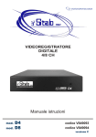
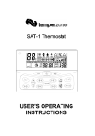
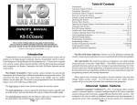
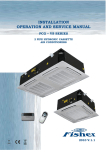
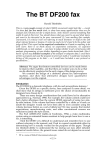
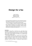
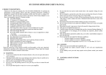
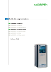
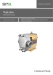
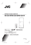
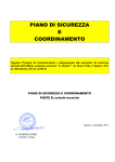
MANUALE D’INSTALLAZIONE E USO INSTALLATION AND OPERATING MANUAL Series WALL ATTENZIONE – WARNING Prima di usare l’apparecchio, leggere questo manuale accuratamente ed eseguire le operazioni in modo corretto. Le istruzioni descritte in questa sezione sono riferite per la sicurezza di un corretto funzionamento; accertarsi di osservarle. Before using the equipment, please read this manual carefully and carry correctly out all the operations. The section explains how to use the equipment safely and correctly; please be sure to follow these instructions. MIU.WL.I.GB.011.02/08 CASSETTE IDRONICHE HWN HYDRONIC HIGH WALL HWN SERIES INDICE - INDEX 1. Descrizione generale – General Descriptions 3 2. Dati e specifiche del prodotto – Product Data and Specifications 5 3. Disegno quotato – Dimensional Drawing 6 4. Installazione dell'unità – Installation of Unit – Installation der Einheit – Installation de l'unité 7 5. Piastra di supporto e preparazione della parete – Mounting plate and wall preparation 9 6. Scarico – Drainage 12 7. Apertura e chiusura del coperchio – opening closing of lift cover 13 8. CONDOTTI DELL'ACQUA CON VALVOLA - WATER PIPING WITH VALVE 17 9. TELECOMANDO CON OROLOGIO IN TEMPO REALE – REAL TIME CLOCK CONTROL HANDSET 18 10. PANNELLO DI CONTROLLO A PARETE CABLATO CON OROLOGIO IN TEMPO REALE – 20 REAL TIME CLOCK WIRED WALL PAD CONTROL 11. Sistema di gestione computerizzata - Computer management system control 24 12. Schemi dei collegamenti master-slave – Wiring diagrams with master-slave 36 1 2 1. DESCRIZIONE GENERALE - GENERAL DESCRIPTION Il ventilconvettore a parete è progettato per soddisfare e superare elevati requisiti di efficienza, silenziosità ed estetica. L'involucro dal profilo slanciato e pulito si intona con qualsiasi tipo di arredamento. Il microprocessore assicura un accurato controllo ambientale. The High wall Fan coil is designed to meet and exceed the demanding requirements for efficiency, quiet operation and good looks. The sleek profile and elegantly styled cabinet will compliment any interior design theme. The Microprocessor assures accurate environmental control. INVOLUCRO – CABINET L'involucro dal design accattivante è realizzato in polipropilene durevole e autoestinguente. Il colore grigio argento e gli spigoli arrotondati gli conferiscono un look moderno. The cosmetically attractive cabinet is constructed of durable flame resistant polypropylene. The silver grey colour and rounded corners provide for its contemporary appearance. BATTERIA AD ACQUA - WATER COIL La batteria ad acqua presenta una ampia superficie di trasferimento termico che utilizza la più recente tecnologia in materia di profilo delle alette. Questo elemento si abbina alla sicurezza garantita dallo spessore della parete del tubo realizzato in design tradizionale. La batteria ad acqua è anche dotata di valvola di sfiato dell'aria e di valvola di spurgo dell'acqua. The water coil has a large heat transfer surface utilizing the latest technology in fin profile. This is combined with security in tube wall thickness of traditional design. The water coil is also equipped with purge air valve and purge water valve. TUBI FLESSIBILI - FLEXIBLE HOSES Il tubo in elastomero sintetico con calza intrecciata esterna in acciaio inox e connettori in ottone consente raccordi rapidi e a basso costo senza necessità di brasature. Synthetic elastomer tube with stainless steel outer braiding and brass connectors makes for quick and low cost connections with no brazing. VENTILATORE e MOTORE - BLOWER and MOTOR Incorporando solo motori di ventilatori a condensatore permanente ad alto fattore di potenza specificamente progettati e collaudati, il ventilatore tangenziale garantisce il non plus ultra in tema di efficienza del flusso d'aria e di SILENZIOSITÀ di esercizio. Incorporating only specially designed and tested high power-factor permanent split capacitor type blower motors, the tangential blower wheel provides the optimum in airflow efficiency and QUIET operation. FILTRI – FILTERS Standard su tutti i modelli vengono forniti filtri dell'aria lavabili a maglia fine. Delle linguette ubicate sul fronte dell'unità possono essere sbloccate consentendo di estrarre facilmente i filtri dal basso. Non sono necessari utensili, né è necessario smontare l'apparecchiatura. 3 Standard to all models are washable fine mesh air filters. Tabs located on the front of the unit can be unsnapped and the filters easily slide downward for removal. No tools are required, nor are dismantling of the equipment. GRIGLIA DI DISTRIBUZIONE DELL'ARIA - AIR GRILLE DISTRIBUTION Grazie alla presenza di alette del deflettore e di palette direzionali indipendenti, l'aria di mandata può essere automaticamente distribuita e personalizzata in modo da dirigere l'aria dove lo si desidera. Equipped with both deflector blades and independent directional vanes, supply air can automatically be distributed and customized to direct the air where desired. CONTROLLO TRAMITE MICROPROCESSORE - MICROPROCESSOR CONTROL Per trovare dettagli completi, fare riferimento alla sezione dei Controlli. Caratteristiche principali: - Controllo Master-Slave - Modalità raffreddamento, riscaldamento, ventilatore - Funzioni Sleep, Autoriavvio con Memoria - Funzione timer per avviare o arrestare l'unità fino a 18 ore - Telecomando intuitivo - Termostato di sicurezza per riscaldamento e raffreddamento - Indicazione dello stato per boiler e refrigeratore - Controllo tramite valvola a 3 vie - Pannello di controllo opzionale a parete con timer di 24 ore e orologio in tempo reale. - Pannello di Controllo Manuale nell'Involucro See Control Section for complete details. Main features: ~ Computer management system control ~ Master-Slave control ~ Cool, Heat, Fan, Dehumidify, Auto modes ~ Sleep, AutoFan, Auto-Restart with Memory functions ~ Timer function to start or stop the unit up to 24 hours ~ Remote Control Handset ~ Heat and Cool Temperature Safety Cut Out ~ Status Indication to boiler and chiller ~ 3 way valve control ~ Wired Wall Pad Control with 24 hours timer ~ Manual Control Panel in Cabinet 4 2. VENTILCONVETTORI DA PARETE IDRONICI - SERIE HWN – HYDRONIC HIGH WALL UNITS - HWN SERIES Tipo Raffreddante e Riscaldante – Numero Modelli Cooling and Heating Type - Model Numbers Dati Nominali di Prestazioni e Elettrici Performance and Electrical Ratings Alimentazione (V/PH/Hz) Power Supply (V/PH/Hz) Potenza Frigorifera Nominale * (kW) Nominal Cooling Capacity * (kW) Potenza Frigorifera Sensibile (kW) Sensible Cooling Capacity (kW) Potenza Termica Nominale ** (kW) Nominal Heating Capacity ** (kW) Potenza Termica Nominale *** (kW) Nominal Heating Capacity *** (kW) Portata aria alle velocita' Alta/Media/Bassa (m3/min) Airflow at H/M/L Speeds (m3/min) Livello di Rumore alle Velocita' Alta/Bassa (dBA) Sound Level at High/Low Speed (dBA) Portata d'acqua (l/min) Water Flow Rate (l/min) Raffedamento Perdita di Carico Batteria (kPa) Cooling Coil Pressure Drop (kPa)) Riscaldamento Heating Corrente di Esercizio (Amps) Running Current (Amps) Assorbimento (w) Power input (w) Tipo Attacco Condotti d'acqua Water Piping Connection Type D.E. Acqua (Ing./Usc.) (Pollici) Water (in/out) O.D. (in.) Larghezza (mm) Width (mm) Altezza(mm) Height(mm) Profondità (mm) Depth (mm) Peso Netto Net Weight HWN 10 HWN 30 HWN 40 230/1/50 1,4 2,3 4,0 1 1,5 2,5 2,2 3,2 5,7 3,3 4,7 8,5 6,0 / 4,0 / 2,5 7,9 / 5,3 / 3,3 10,8 / 7,5 / 4,4 35 / 32 38 / 32 45 / 39 4,20 7,00 11,67 25 10,5 24 25,3 11 25 0,123 0,180 0,254 28 41 58 Connettore Femmina Female Connector 1/2" 1/2" 3/4" 870 1030 1160 270 320 330 176 196 198 11,5 13,5 16,5 *Raffreddamento: 27°C (50%UR) temperatura aria ingresso, 7°C temperatura acqua ingresso e 12°C temperatura acqua uscita. **Riscaldamento: 20°C temperatura aria ingresso, 50°C temperatura acqua ingresso, 43,5°C temperatura acqua in uscita ***Riscaldamento: 20°C temperatura aria ingresso, 70°C temperatura acqua ingresso,60°C temperatura acqua uscita Le portate d’acqua di riscaldamento sono uguali alle portate di raffreddamento. *Cooling: 27°C (50% UR) entering air temperature, 7°C entering water and 12°C leaving water temperature. **Heating: 20°C entering air temperature, 50°C entering water, 43,5°C leaving water temperature. ***Heating: 20°C entering air temperature, 70°C entering water, 60°C leaving water temperature. Heating water flow rates are the same as cooling flow rates. N. MODELLO MODEL NO. HWN 10 HWN 30 HWN 40 ALTEZZA ALETTE (mm) FIN HEIGHT (mm) 209.8 225 225 LUNGHEZZA ALETTE (mm) FIN LENGTH (mm) SPAZIATURA ALETTE (mm) FIN SPACING (mm) N. DI RANGHI NO. OF ROWS N. DI CIRCUITI NO. OF CIRCUITS 495 610 690 1.7 1.7 1.7 2 2 3 3 3 4 Il colore del pannello frontale è RAL 9010 Front panel colour is RAL 9010 5 3. DISEGNO QUOTATO - DIMENSIONAL DRAWING C B D E A F HWN 10 HWN 30 HWN 40 A 176 196 198 B 270 320 330 C 870 1030 1160 D 58 50 58 E 696 813 916 F 87 100 110 6 4. INSTALLAZIONE DELL'UNITA' - INSTALLATION OF UNIT 4. 1 UBICAZIONE DELL'UNITÀ - LOCATION OF THE UNIT Selezionare l'ubicazione del ventilconvettore con le seguenti considerazioni: 1. 2. 3. 4. 5. 6. Il fronte della presa e del diffusore d'aria deve essere libero da ostruzioni. L'aria deve fluire liberamente. La parete su cui montare l'unità deve essere sufficientemente rigida da non risuonare e produrre rumore. L'ubicazione deve consentire un facile accesso per il collegamento dei tubi dell'aria oltre che un facile scarico. Assicurarsi che lo spazio libero da ogni lato del ventilconvettore sia conforme al disegno seguente. L'altezza dal pavimento deve essere superiore al livello degli occhi. Evitare di installare l'unità esposta alla luce solare diretta. Select the location of the fan coil unit with the following considerations: 1. 2. 3. 4. 5. 6. The front of the air inlet and outlet should be free from any obstructions. The air should flow freely. The wall where the unit is to be mounted should be stiff enough not to resonate and produce noise. The location should allow easy access to install the connecting water pipes and where drainage can be easily obtained. Ensure the clearance on every side of the fan coil unit conforms to the following drawing. From the floor the height should be more than eye level. Avoid installing the unit in direct sunlight. SOPRA IL LIVELLO DEGLI OCCHI HIGHER THAN EYE LEVEL SOPRA IL LIVELLO DEGLI OCCHI HIGHER THAN EYE LEVEL LIVELLO PAVIMENTO FLOOR LEVEL Lo spazio libero necessario per interventi di manutenzione e assistenza è sopra raffigurato. Tutte le dimensioni sono in millimetri 7. 8. Il ricevitore di segnali presente sull'unità deve essere tenuto lontano da qualsiasi sorgente di emissioni ad alta frequenza. Tenere l'unità lontana anche da lampade fluorescenti, in quanto anch'esse potrebbero incidere sul funzionamento del sistema di controllo. 9. Per evitare interferenze elettromagnetiche nel sistema di controllo, assicurarsi che i cavi di segnale siano installati lontano da cavi elettrici da 220-240 VAC 10. Dove si trovano interferenze elettromagnetiche usare un cavo schermato. 11. Installare un anello magnetico se esiste un’interferenza nella rete elettrica. Required clearance for maintenance and servicing is shown above. All dimensions are in millimetres. 7. 8. 9. The signal receiver on the unit must be kept away from any high frequency emission source. Also keep the unit away from fluorescent lamps, which also may affect the control system. To avoid electromagnetic control system interference ensure control wires are installed separately from 220-240 VAC power wires 10. Where electromagnetic waves exist use shielded sensor cable. 11. Install a noise filter if any harmful noise exists in the power supply 7 4. 2 1. 2. 1. 2. PENETRAZIONE NELLA PARETE – WALL PENETRATION Praticare un foro nella parete come raffigurato nello schema. Il foro deve essere praticato con una lieve pendenza verso il basso in direzione del lato esterno al fine di consentire il deflusso dell'acqua di condensa. Drill a hole in the wall as shown in diagram. Hole should be drilled with a slight downward slant to the outdoor side to enable the condensed water to flow. PARETE INTERNA INSIDE WALL PARETE ESTERNA OUTSIDE WALL TUBO PROTETTIVO IN PVC DURO HARD PVC PIPE FOR PROTECTION 8 5. PIASTRA DI MONTAGGIO E PREPARAZIONE DELL’UNITA’ WALL - MOUNTING PLATE AND WALL PREPARATION HWN 10 HWN 30 ZONA INGRESSO TUBI - Unità interna (linea tratteggiata) Indoor unit (dotted line) INLET PIPE AREA 9 Unità interna (linea tratteggiata) Indoor unit (dotted line) HWN 40 ZONA INGRESSO TUBI 5. 1 - INLET PIPE AREA INSTALLAZIONE DEL PANNELLO DI FISSAGGIO – INSTALLING FIXING BOARD A. A. Parete in laterizio o calcestruzzo Brick or Concrete Wall 1. 2. 3. Collocare il pannello di fissaggio contro la parete assicurandosi che sia orizzontale, quindi tracciare i fori da praticare. Praticare i fori, inserire i tappi a vite a cui va assicurato il pannello di fissaggio. Prima di stringere definitivamente le viti, eseguire un controllo finale assicurandosi che il pannello sia orizzontale. 1. 2. 3. Place the fixing board flush against the wall making sure it is horizontal, then trace out the holes to be drilled. Drill holes, insert screw plugs to which the fixing board can be secured. Before fixing screws tightly make a final check to make sure board is horizontal. B. B. Parete di legno Wooden Wall 1. 2. 3. 4. 1. 2. 3. 4. . Assicurare il pannello di fissaggio alle travi onde prevenire vibrazioni. Se non vi sono travi, si può solo assicurare il pannello di fissaggio con un maggior numero di viti al fine di aumentare la resistenza. Usare le viti in dotazione per assicurare il pannello, ma sincerarsi che sia orizzontale prima di assicurarlo. Una volta assicurato il pannello, provare a tirarlo per controllare se sia sufficientemente resistente da tenere in sede l'unità. Secure the fixing board to the beams to prevent vibration. If there is no beam then you can only secure the fixing board with more screws to add strength. Use the accompanying screws to secure the board, but make sure the board is horizontal before securing it. After securing the board, pull it to see whether it is strong enough to hold the unit in place. PANNELLO DI FISSAGGIO FIXING BOARD VITI SCREW COLLOCARE PANNELLO DI FISSAGGIO SU TRAVE PUT THE FIXING BOARD ON BEAM FOR WOODEN WALL 10 1. 2. Collegare anzitutto i condotti dell'acqua e il tubo di scarico agli attacchi sul retro dell'unità, quindi installare l'unità al pannello di fissaggio, come raffigurato. Una volta sospesa l'unità, premerla sul pannello di fissaggio (dopo averla installata, tirarla verso di sè onde assicurarsi che sia saldamente assicurata in sede). 1. First connect the water piping and the drain pipe to the connection at the back of the unit, then install the unit to the fixing board as shown. 2. After hanging the unit, press, it to the fixing board (after installing it pull it towards yourself making sure it is properly in place and secured). MEGLIO SE C’È’ UNA TRAVE NELLA PARETE IN LEGNO WOODEN WALL SHOULD HAVE BEAM PANNELLO DI FISSAGGIO FIXING BOARD FORMA A GANCIO DELLA SEZIONE INFERIORE HOOK DESIGN OF THE BOTTOM SECTION PANNELLO DI FISSAGGIO FIXING BOARD GANCIO HOOK AVVOLTO CON NASTRO WRAPPED BY TAPE UNITA’ INTERNA INDOOR UNIT La sonda ambiente è fornita di norma all’interno dell’unità. È tuttavia possibile portare la sonda fuori dall’unità facendola passare attraverso la feritoia come indicato nella figura. The probe is installed inside the unit. It is also possible to bring the probe inside the unit through the little hall indicated by the arrow. 11 6 SCARICO – DRAINAGE 1. 2. Per consentire lo scarico, prevedere l'installazione in pendenza. Il tubo di scarico, come raffigurato sotto, non può avere una pendenza fluttuante, in quanto farebbe ristagnare l'acqua danneggiando il tubo. 1. 2. For the sake of drainage, design installation with gradient. Drain hose as shown below, cannot have a fluctuating gradient or it will store water and damage the pipe PENDENZA NON FLUTTUANTE NO FLUCTUATING GRADIENT PENDENZA NON FLUTTUANTE NO FLUCTUATING GRADIENT PENDENZA VERSO IL BASSO SLOPE DOWN PENDENZA VERSO IL BASSO SLOPE DOWN NON COLLOCARE LO SCARICO IN ACQUA DON’T PLACE DISCHARGE IN WATER 3. Una volta completato lo scarico, fare delle prove riempiendo d'acqua la bacinella di raccolta nell'angolo sinistro del ventilconvettore onde accertarsi che lo scarico sia libero e non ostruito. Vedere lo schema sotto riportato. 3. When drainage has been completed, it should be tested by filling the drain tray at the left corner of the fan coil unit with water to ensure drainage is clear and unobstructed. See diagram below. USCITA ARIA AIR OUTLET RACCORDO A T T-SHAPED CONNECTOR USCITA DI SCARICO DRAINAGE OUTLET 12 7. 4. 5. Una volta collegato il tubo di scarico, applicare l'isolamento. Se il tubo di scarico orizzontale è troppo lungo, aggiungere un diffusore d'aria, ossia un connettore a T a 3 vie (in PVC) come sopra raffigurato. 4. 5. After connecting the drain pipe, insulation should be applied. If the horizontal drain pipe is too long an air outlet should be added, i.e. a T shaped 3-way connector (PVC material) as shown above. APERTURA E CHIUSURA DEL COPERCHIO OPENINGCLOSING OF LIFT UP COVER Aprire il coperchio alzandolo come indicato Open the lift up cover by lifting up at positions as indicated. Chiudere il coperchio premendo verso il basso come indicato nelle due posizioni, finchè è completamente chiuso Close the lift up cover by pressing down at the two positions as indicated until the cover is firmly closed. Come rimuovere il pannello frontale 1. 2. 3. 4. 5. Portare il deflettore in posizione orizzontale. Rimuovere le coperture delle viti sotto il deflettore, quindi rimuovere le viti. Aprire il pannello afferrandolo da entrambi i lati. Rimuovere le viti rimanenti situate nella parte centrale. Afferrare la parte più bassa del pannello frontale e tirare fuori l’intero pezzo. Sfiato dell’aria 1. 2. 3. 4. 5. Dopo aver collegato i tubi di entrata e uscita dell’acqua alle principali linee, accendere l’interruttore principale ed azionare l’unità in modalità RAFFREDDAMENTO. Aprire la valvola di entrata dell’acqua fino a riempire la batteria. Controllate le eventuali perdite d’acqua in tutti i collegamenti. Se non viene riscontrata nessuna perdita, aprite la valvola di sfiato con una chiave fissa (n. 10). Quindi sfiatare l’aria intrappolata nella batteria. Durante l’operazione fare attenzione a non toccare parti elettriche. Chiudere la valvola di sfiato quando non appaiono più bolle d’aria. Aprire la valvola di uscita dell’acqua. Drenaggio della batteria 1. 2. Aprite la valvola di spurgo dell’acqua con un cacciavite. Chiudete la valvola di spurgo dell’acqua quando non esce più acqua. 13 HOW TO REMOVE THE FRONT COVER ASSEMBLY 1. 2. 3. 4. 5. Set the horizontal louver to horizontal position. Remove the screw caps below the louver, and then remove the mounting screws. Open the lift up cover by grasping the panel at both sides. Remove the remaining screws located at the centers. Grasp the lower part of the front cover and pull the entire assembly out and up towards you. AIR PURGING 1. After connecting the water inlet and outlet pipes to the main supply lines, turn on the main breaker and operate the unit in COOLING mode. 2. Open the water inlet valve and flood the coil. 3. Check all connections for water leakage, if no leak is found open the air vent valve with an open end wrench (No.10). Then purge the air trapped inside the coil. When performing this, take care not to touch the electrical parts. 4. Close the purging valve when no bubbles appear. 5. Open the water outlet valve. COIL DRAINING 1. 2. Open the water drain valve with a screw driver. Close the water drain valve when no water appears. 1. SFIATO ARIA AIR PURGE SPURGO ACQUA WATER PURGE 14 CABLAGGIO DI COLLEGAMENTO – CONNECTING WIRING VERBINDUNGSKABEL/DRÄHTE – CONNEXION DU CABLAGE 1. Dopo aver rimosso il coperchio frontale, collegare i fili elettrici 1. After removing the front cover, connect the field wiring. Morsettiera Terminal block Scatola elettrica Control box Pannello base Base pan 2. Lunghezza dell’isolamento del cavo di collegamento da rimuovere 2. Length of connection cable insulation to be removed. 3. Inserire completamente il cavo di collegamento nel morsetto ed assicurarlo avvitandolo molto stretto. 3. Insert the connecting cable fully into the block and secure it by screw tightly. 4. Fermare il cavo di collegamento 4. Secure the connecting cable. morsettiera Terminal block Cavo di alimentazione (non fornito). Power supply cord (not supplied) Attenzione Assicurarsi di aver tolto l’alimentazione di energia elettrica prima di aprire il coperchio per operare. Fare sempre riferimento agli schemi elettrici riportati. 15 Rispettare le normative riguardo gli impianti elettrici locali. Nota: Aggiungere l’isolamento ai tubi flessibili Caution Be sure to turn off the main power supply before opening the lift up cover for servicing. Always refer to the wiring diagrams supplied. Check local electrical codes and also any specific wiring codes. 16 8. CONDOTTI DELL'ACQUA CON VALVOLA - WATER PIPING WITH VALVE ATTUATORE GASKET 230V 50Hz 5w GUARNIZIONE GASKET TUBO FLESSIBILE FLEXIBLE HOSE VALVOLA VALVE GUARNIZIONE GASKET Nota: Per le unità installate con valvola, aggiungere l'isolamento alla valvola e ai raccordi n. 1 e n. 2, come sopra raffigurato. Note: For units installed with valve add insulation to valve and fittings # 1, # 2 as shown above. 17 9. TELECOMANDO CON OROLOGIO IN TEMPO REALE – REAL TIME CLOCK CONTROL HANDSET 1 8 7 4 9 5 6 2 10 3 12 11 14 13 18 1 Sorgente di trasmissione usata per inviare il segnale di controllo all’unità di condizionamento. Transmission source used for sending control signal to air-conditioning unit 2 Pulsante ON/OFF: premendo questo pulsante, l’unità di condizionamento verrà accesa o spenta. NOTA: il pulsante ON/OFF non sarà in funzione quando viene impostato il programma giornaliero ON-OFF button: Pressing this button will turn the air-conditioning unit on or off. NOTE: on-off button ONOFF will not work when continuous daily operation is set 3 Pulsante FAN: premere il pulsante per selezionare velocità bassa, media, alta o automatica. Fan button: press to select Low, Medium; High or Auto speed 4 Pulsante Mode: premere il pulsante per selezionare la modalità auto, raffreddamento, deumidificazione, ventilazione o riscaldamento. Mode button: Press button to select Auto mode, Cool, Dehumidify, Fan or Heat mode 5 Pulsante swing: distributore di aria in tutte le direzioni. Swing button: air conditioning in all mode 6 Pulsante NETWORK: permette di impostare tutti i parametri sull’unità centrale. Poi, premere il pulsante per 3 secondi e apparirà l’icona NETWORK. Tutti i parametri sono stati inviati all’unità slave. Network button: you can set all parameters on the master unit. Then press the button for 3 seconds, and network icon will appear. All parameters have been sent to slave units. 7 Display a cristalli liquidi. LCD display 8 Pulsante sleep: la modalità sleep regola automaticamente la temperatura e risparmia energia mentre state dormendo. Sleep button: sleep mode will automatically adjust temperature and save energy when you are sleeping 9 Pulsante verso l’alto: premere il pulsante per aumentare la temperatura di 1°C alla volta. (Max 30°C). Pulsante verso il basso: premere il pulsante per diminuire la temperatura di 1°C alla volta.(Max 16°C). Up button: press button to increase temperature 1C step.(Max30C). Down button: press to decrease temperature 1C step.(min:16C) 10 11 Pulsante TIMER-ON: premere il pulsante una volta, lampeggerà l’icona Timer-on. Poi, premere il pulsante TIMER-SET per impostare il tempo TIMER-ON di 10 minuti alla volta.Premere ancora il pulsante ed il timeron sarà impostato. Premere ancora il pulsante e la modalità Timer-on verrà cancellata. Timer ON-OFF button: press the button once, the timer On icon will blink. Then press Timer Set button to set timer-On in 10 minute steps. Press the button again and timer on is set. Press the button again and timer-on mode is cancelled Pulsante TIMER-OFF: premere il pulsante una volta, lampeggerà l’icona Timer-off. Poi, premere il pulsante TIMER-SET per impostare il tempo TIMER-OFF di 10 minuti alla volta. Premere ancora il pulsante ed il timeroff sarà impostato. Premere ancora il pulsante e la modalità Timer-off verrà cancellata. Timer off button: press the button once, the timer-off icon eill blink. Then press Timer-set button to set timer-off in 10 minute steps. Press the button again and timer-off is set. Press the button again and timer-Off mode is cancelled 12 Pulsante RESET: premere il pulsante per azzerare il telecomando. Reset button: press button to restart remote Handset 13 Pulsante TIMER-SET: quando si imposta l’orologio, premere il pulsante per aumentare di un minuto alla volta. Quando si imposta il timer-on o il timer-off, premere il pulsante per aumentare di 10 minuti alla volta. Impostazione del Timer ON e OFF del programma giornaliero: premere il pulsante per 3 secondi, apparirà l’icona di impostazione del ciclo timer ON e OFF. Premere ancora il pulsante per 3 secondi e la modalità di esercizio giornaliero continuo del ciclo timer ON e OFF verrà cancellata. Timer set button: when you set the time clock, press button to increase by 1 minute Step. When you set the timeron and timer-off, press button to increase by 10 minute step 19 14 10. 1 Pulsante CLOCK: quando si cambiano le batterie, si deve azzerare l’orologio. Dopo aver installato le batterie nuove, l’ora sull’orologio lampeggerà. Quindi premere il pulsante CLOCK perchè l’ora non lampeggi più. Premere il pulsante TIMER-SET per aumentare l’ora di un minuto alla volta. Alla fine premere ancora il pulsante CLOCK. Clock button: when you change the batteries, you must reset the clock time. After you install the new batteries, the clock time will blink. Then, press the clock button, the clock time will not blink. Press Time-set button to increase the time by 1 minute step. At last press the clock button again PANNELLO DI CONTROLLO A PARETE CABLATO CON OROLOGIO IN TEMPO REALE – REAL TIME CLOCK WIRED WALL PAD CONTROL Pulsante ON/OFF: premendo il pulsante, l’unità verrà accesa o spenta ON/OFF ButtonPressing the button will turn the unit on or off. 20 2 Pulsante ventilazione: premere il pulsante per selezionare la velocità automatica, bassa, media o alta Fan ButtonPress the button to select Auto,Low, Medium or High speed. 3 Pulsante modalità: premere il pulsante per selezionare le modalità: automatico, raffreddamento, deumidificazione, ventilazione o calore. Mode ButtonPress the button to select Auto, Cool, Dehumidification, Ventilation or Heat mode. 4 5 6 7 Pulsante di regolazione della temperatura: premere il pulsante su per aumentare la temperatura di 1 C alla volta (max: 30 C). Premere il pulsante giù per diminuire la temperatura di 1 C alla volta (max: 16 C). Temperature Up and Down ButtonPress Up Button to increase temperature 1 step. (Max: 30 )Press Down Button to decrease temperature 1 C step. (min: 16C) Pulsante sleep: la modalità sleep imposta automaticamente la temperatura e risparmia energia durante le ore notturne. Sleep Button Sleep mode will automatically adjust temperature and save energy when you are sleeping. Pulsante network: premere il pulsante per 3 secondi. Apparirà il segnale di rete. Potete controllare tutte od ognuna delle unità slave dall’unità master Network Button:Press the button for 3 seconds, then the network signal will appear. You can control all or each of the slave units by controlling the master unit. Pulsante per impostare la rotazione del deflettore Swing Button 8 Pulsante Enter: per evitare un cattivo funzionamento, tutte le impostazioni (eccetto il pulsante ON/OFF) sono valide solo dopo aver premuto il pulsante ENTER Enter Button: In order to avoid mis-operation, all settings (except ON/OFF Button) are valid after pressing Enter Button. . 9 Pulsante Clock: premendo il pulsante, lampeggerà “AM”, premere i pulsanti per impostare l’ora Clock Button Press the clock button, “AM” lights, then press time up or down button set time. 10 Pulsante Timer-On, Timer Off. Quando l’unità è accesa o spenta, premere il pulsante per inserire o disinserire il Timer. Premere il pulsante Su o Giù per impostare il tempo del timer ON o OFF. Timer-On Timer-Off Button: When the unit is on or off, press the button to set timer off or on. Press time up or down button to set timer on or off time. 11 Impostazione ora - Setting time (hour) 12 Allarme errore - Error Alarm - 13 Timer ON. Timer OFF - Timer ONTimer OFF 14 Error Mark: se viene visualizzato Error Mark 1, il sensore di temperatura ambiente sta funzionando male; se viene indicato Error Mark 2, c’è un malfunzionamento nella pompa di scarico condensa. Error Mark: If error mark 1 is shown, the room temperature sensor is malfunctioning. If error mark 2 is shown the condensate pump is malfunctioning. 21 15 Numero unità: N. 00 è l’unità master. È possibile controllare tutte le singole unità separatamente dall’unità master. I N. 01-31 rappresentano le unità slave. Unit Number: No.00 is the master unit. You can control all or each of the units by the master unit. No.01-31 are slave units. 16 Modalità automatica, raffreddamento, deumidificazione, ventilazione o riscaldamento Automatic, Cool, Dehumidification, Ventilation or Heat 17 sensore temperatura ambiente: usando il Wall Pad, il sensore lavora automaticamente al posto del sensore installato nella scheda dell’unità Room Temperature Sensor: When using wall pad, the sensor automatically works instead of the main PCB’s sensor. 18 AM- PM: visualizzazione dell’ ora AM- PM Time display 19 Visualizzatore velocità di ventilazione: Automatica, bassa, media o alta Fan Speed Display: Auto, Low, Medium or High 20 Visualizzatore funzione sleep Sleep Display 21 Visualizzatore swing - Swing Display- 22 Display per la visualizzazione della temperatura impostata Setting Temperature (C) Display 23 Display per la visualizzazione della temperatura ambiente Room Temperature (C) Display 24 Segnale LED - LED Signal 25 Network icon display: quando appare l’icona, è possibile cambiare tutte o solo un parametro delle unità slave, premendo il pulsante TIME UP o TIME DOWN. Dopo aver cambiato i parametri dell’unità master, premere il pulsante Enter: i parametri delle unità slave saranno cambiati Network Icon display: When the icon appears, you can change all or each of the slave units parameters by pressing TIME UP or DOWN button. After you change master unit parameters, press the enter button, The slave units parameters will change. 22 23 11. SISTEMA DI GESTIONE COMPUTERIZZATA - COMPUTER MANAGEMENT SYSTEM CONTROL ABBREVIAZIONI Ts = Temperature impostata Tr = Temperatura ambiente Ti = Sensore di temperatura interna MTV = Valvola motorizzata ABBREVIATIONS Ts = Setting temperature Tr = Room temperature Ti = Indoor temperature sensor MTV = Motorized valve ESERCIZIO DEL SISTEMA SYSTEM OPERATION FUNZIONE UNITA' MASTER E SLAVE • Il quadro di comando può essere impostato o come unità master o come unità slave MASTER AND SLAVE UNIT FUNCTION • The control board can be set either as a master unit or slave unit FUNZIONE UNITA’ MASTER • • L'unità master invia dati sulla propria impostazione all'unità slave. Le impostazioni dell'unità master sono Modalità, Velocità Ventilatore, Temperatura Impostata, Inserimento/Disinserimento Timer, Funzione Sleep e Orientamento. MASTER UNIT FUNCTION • • The master unit sends data on its setting to the slave unit. The master unit settings are Mode, Fan Speed, Set Temperature, On/Off timer, Sleep Function and Swing function. FUNZIONE UNITA’ SLAVE • • • L'unità slave riceve dati sulle proprie impostazioni dall'unità master. All'unità slave è permesso cambiare in una impostazione localmente desiderata a patto che non ci siano successive variazioni sulle impostazioni dell'unità master. Le unità periferiche possono essere impostate individualmente per la funzione sleep, timer on e off. SLAVE UNIT FUNCTION • The slave unit receives data on its settings from the master unit. 24 • • The slave unit is allowed to change to a locally desired setting as long as there are no subsequent changes on the settings of the master unit. The slave units can be set individually for sleep , timer on and off function. INSTALLAZIONE MASTER – SLAVE • • • • • • • Quando si usa il telecomando, per l’unità master assicurarsi che il ponte JP0 sia cortocircuitato e per l’unità slave il JP0 sia aperto prima di dare l’alimentazione. Quando si usa il Wall Pad, il ponte JP0 non funziona. Usare il Wall Pad per impostare l’unità master e le unità slave. Il display del Wall Pad mostrerà il numero di unità 00 per l’unità master ed il numero 01-31 per le unità slave. Consultare la guida del Wall Pad per vedere come impostare l’unità master e le unità slave. Collegare l’unità master con quelle slave usando il filo del telefono. NOTA: usare un cavo R12 in configurazione one to one.. Quando si fornisce l’alimentazione: Con valvola motorizzata: l’unità centrale risponderà con 3 beep. L’unità periferica risponderà con 1 beep. Senza valvola motorizzata: l’unità centrale risponderà con 4 beep.. L’unità periferica risponderà con 2 beep. Se ci sono dei suoni di beep da parte di entrambe le unità, sia master che slave, il JP0 è stato chiuso in entrambe le unità. Quindi non ci sarà comunicazione. Se non si sente nessun beep, nessuna scheda è stata impostata come master. Quindi non ci sarà comunicazione. Una volta che l’unità master riceve il segnale dal telecomando, l’unità stessa invierà i dati. L’unità slave risponderà dopo aver ricevuto i dati. MASTER – SLAVE INSTALLATION • • • • • • When using remote handset, for the master unit ensure the JP0 jumper is shorted and for the slave units JP0 is opened before turning ON the main power supply. When using wired wall pad, JP0 jumper will not function. Use the wall pad to set master and slave units. The wall pad screen will show unit number 00 for master unit, and unit number 01-31 for slave units. See wired wall pad function guide to see how to set master and slave unit. Connect master to slave units with telephone wire. NOTE: Use 4-core cable and one-to-one configuration. When MAIN POWER SUPPLY is ON: With motorized valve: The master unit will respond with 3 beeps. The slave unit will respond with 1 beep. Without motorized valve: The master unit will respond with 4 beeps. The slave unit will respond with 2 beeps. If there are beeping sounds from both master and slave the JP0 on both units is shorted. So, there will be no communication. If there is no beep sound, no board is set as the master unit. So, no communication will occur. Once the master unit receives the signal from the handset, the master unit will send the data. The slave unit will respond after receiving the data. SISTEMA DI GESTIONE COMPUTERIZZATA • • • • È possibile collegare la scheda elettronica al vostro sistema computerizzato attraverso la porta RS-485 direttamente alla porta telefonica del computer usando un semplice di un cavo telefonico. Il collegamento master-slave può anche essere effettuato attraverso il CMS. Il protocollo di comunicazione è ASM. Potete usare il vostro CMS per esaminare lo stato di tutte le unità e controllare le modalità di ognuna: On/Off, Temperatura impostata, valvola aperta o chiusa, la rotazione del deflettore e la velocità di ventilazione. Non è possibile impostare il timer. L’unità master può essere collegata con 31 unità slave con la distanza massima di 1 km. 25 COMPUTER MANAGEMENT SYSTEM • • • • You can connect the control PCB to your computer management system through the RS-485 port direct to your computer telephone port with a telephone line. Master-slave can also be operated through the CMS. The communication protocol is ASM. You can use your CMS to check all units’ status, and control each unit On/Off, Mode, Set Temperature, Valve open or close, Swing function and Fan speed. You cannot control timer. The master unit can be connected with 31 slave units with maximum distance of 1 KM. ACCENSIONE SPEGNIMENTO DEL CONDIZIONATORE Vi sono 3 modi per accendere o spegnere il sistema: • • • premendo il pulsante ON/OFF sul condizionatore d'aria. con il timer programmabile ad ore sul telecomando o sui pannelli di controllo a parete. premendo il pulsante ON/OFF sul telecomando. AIR CONDITIONER ON/OFF There are 3 ways to turn on or off the system: • • • by ON/OFF button on the air conditioner. by hours programmable timer on the handset or wallpad controls. by ON/OFF button on the handset. IMPOSTAZIONE DELL’ACCENSIONE • Quando il segnale di accensione è ricevuto dal condizionatore o in caso di autoriavvio, l'impostazione di Modalità, Velocità Ventilatore, Temperatura Impostata e Orientamento saranno uguali alle ultime impostazioni sul telecomando prima dell'ultimo spegnimento. POWER ON SETTING • When power on signal is received by the air conditioner or in case of auto restart the Mode, Fan Speed, Set Temperature and Swing setting will be the same as the last handset setting before the last power off. CON VALVOLE MOTORIZZATE WITH MOTORIZED VALVE MODO RAFFREDDAMENTO • • • • • • • Se Tr >= Ts+1, è attivo l'esercizio di raffreddamento. MTV è inserita. Il ventilatore interno gira alla velocità impostata. Se Tr <= Ts, l'esercizio di raffreddamento è terminato. MTV è disinserita. Il ventilatore interno gira alla velocità impostata. Il campo di Ts è fra 16 e 30 °C La velocità del ventilatore interno può essere impostata ai livelli basso, medio, alto e "auto" Quando viene aperta, MTV richiede 30 secondi prima di essere completamente inserita. Quando viene chiusa, MTV richiede 120 secondi prima di essere completamente disinserita. Quando l’unità viene spenta, il ventilatore ritarda lo spegnimento di 5 secondi. 26 COOL MODE • • • • • • • If Tr≥Ts+1°C, cool operation is activated. MTV is turned on. Indoor fan runs at set speed. If Tr≤Ts, cool operation is terminated. MTV is turned off. Indoor fan runs at set speed. The range of Ts is 16 to 30 °C. Indoor fan speed can be adjusted for low, medium, high and auto. When turned on, MTV requires 30 seconds before it is fully open. When turned off, MTV requires 120 seconds before it is fully closed. When the unit is turned off, indoor fan will delay for 5 seconds before it is turned off. PROTEZIONE DELLA BATTERIA DALL A BASSA TEMPERATURA • • Se Ti≤2°C per 2 minuti, MTV è disinserita. Se il ventilatore è impostato alla bassa velocità, essa lavorerà a velocità media. Se è impostato alla media o alta velocità, funzionerà alla velocità impostata. Quando Ti > 5 °C, MTV è inserita. Il ventilatore interno gira alla velocità impostata. LOW TEMPERATURE PROTECTION OF INDOOR COIL • • If Ti≤2°C for 2 minutes, MTV is turned off. If indoor fan is set for low speed, it will run at medium speed. If it set at medium or high speed, it will keep running at the same speed. If Ti≥5°C for 2 minutes, MTV is turned on. Indoor fan runs at set speed. MODALITA’ VENTILATORE • • Il ventilatore interno gira alla velocità impostata mentre la MTV viene disinserita. La velocità del ventilatore interno può essere impostata ai livelli basso, medio, alto e "auto" FAN MODE • • Indoor fan runs at the set speed while MTV is turned off. Indoor fan speed can be adjusted for low, medium, high and auto. MODALITA’ RISCALDAMENTO • • • • • • Se Tr <= Ts-1, è attivo l'esercizio di riscaldamento, MTV è inserita. Il ventilatore interno gira alla velocità impostata. Se Tr>= Ts, l'esercizio di riscaldamento è terminato, MTV e il ventilatore interno sono disinseriti. Il campo di Ts è fra 16 e 30 °C La velocità del ventilatore interno può essere impostata ai livelli basso, medio, alto e "auto" Quando viene inserita, MTV richiede 30 secondi prima di essere completamente aperta Quando viene disinserita, MTV richiede 120 secondi prima di essere completamente chiusa. HEAT MODE • • • If Tr <= Ts-1, heat operation is activated, MTV is turned on. Indoor fan runs at the set speed. If Tr>= Ts, heat operation is terminated, MTV and indoor fan are turned off. The range of Ts is 16 to 30 °C 27 • • • Indoor fan speed can be adjusted for low, medium, high and auto When turned on, MTV requires 30 seconds before it is fully open When turned off, MTV requires 120 seconds before it is fully closed PRERISCALDO E PROTEZIONE DELLA BATTERIA INTERNA • • • Se Ti <= 38 °C, MTV è inserita, il ventilatore interno è disinserito . Se Ti >= 38 °C, MTV è inserita. Il ventilatore interno parte alla velocità impostata. Se il sensore di temperatura della batteria interna è rotto, il tempo “pre-heat” è impostato per 2 minuti e lil ventilatore lavora alla velocità impostata PRE-HEAT AND PROTECTION OF INDOOR COIL • • • If Ti <= 38 °C, MTV is turned on, indoor fan is turned off. If Ti >= 38 °C, MTV is turned on. Indoor fan starts at the set speed. If indoor coil temperature sensor is damaged, pre-heat time is set for 2 minutes and indoor fan runs at set speed. POST RISCALDO • • • Se Ti > 38 °C, MTV è disinserita, il ventilatore interno resta inserito. Se Ti < 38 °C, MTV è disinserita. Il ventilatore funziona per 30 secondi e si ferma per 3 minuti a ripetizione Se il sensore di temperatura della batteria è rotto, il tempo di “post-heat” è impostato per 3 minuti e il ventilatore lavora alla velocità impostata POST HEAT • • • If Ti>38°C, when MTV is off and indoor fan continues to run at set speed If Ti<38°C, when MTV is off. Indoor fan runs 30 seconds and stops 3 minutes repeatedly. If indoor coil temperature sensor is damaged, post-heat time is set for 3 minutes with indoor fan running at set speed. PROTEZIONE PER ECCESSO DI CALORE DELLA BATTERIA INTERNA • • • Se Ti≥75°C, MTV è disinserita e il ventilatore interno rimane acceso e funziona alla velocità impostata. Se Ti<70°C, MTV è inserita e il ventilatore interno rimane acceso e funziona alla velocità impostata Se il sensore di temperatura della batteria interna è rotto, la modalità di protezione diventa obsoleta e l’unità lavorerà con i tempi impostati di “pre-heat” e “post-heat”. OVER HEAT PROTECTION OF INDOOR COIL • • • If Ti≥75°C, MTV is turned off, and indoor fan remains on and runs at set speed. If Ti<70°C, MTV is turned on and indoor fan remains on and runs at set speed. If indoor coil temperature sensor is damaged, the protection mode will become obsolete and the unit will work as the Pre-heat and Post-heat set times MODALITA’ DI DEUMIDIFICAZIONE • SeTr ≥ 25°C, MTV sarà accesa per 3 minuti e spenta per 4 minuti. 28 • • Se 16°C≤Tr<25°C, MTV sarà accesa per 3 minuti e spenta per 6 minuti. Se Tr<16°C, MTV sarà spenta. DEHUMIDIFICATION MODE • • • If Tr≥25°C, MTV will be ON for 3 minutes and OFF for 4 minutes. If 16°C≤Tr<25°C, MTV will be ON for 3 minutes and OFF for 6 minutes. If Tr<16°C, MTV will be turned off. MODALITA’ AUTOMATICA RISCALDAMENTO – DEUMIDIFICAZIONE - RAFFREDDAMENTO • • • • • • Nella modalità automatica la temperatura del sistema impostata è di 24° e la ventilazione interna funziona in modalità di ventilazione automatica. Se Tr<21°C, l’unità funzionerà in modalità riscaldamento. Se Tr>25°C, l’unità funzionerà in modalità raffreddamento. Se 21°C≤Tr≤25°C, l’unità funzionerà in modalità deumidificazione. Una volta che l’unità viene accesa in modalità automatica, funzionerà in questa modalità e non verrà convertita. Se l’unità è rimasta spenta per 2 ore, quando viene accesa, selezionerà la modalità di esercizio a seconda della temperatura ambiente . AUTO HEAT-DEHUMIDIFICATION-COOL MODE • • • • • • In auto mode, the set temperature of the system is 24°C and the indoor fan runs in auto fan mode. If Tr<21°C, the unit will operate in heat mode. If Tr>25°C, the unit will operate in cool mode. If 21°C≤Tr≤25°C, the unit will operate in dehumidification mode. Once the unit is turned on in auto mode, it will operate in that mode and will not changeover. If the unit has been turned off for 2 hours, when turning on the unit, it will select the operating mode depending on the room temperature. SENZA VALVOLE MOTORIZZATE WITHOUT MOTORIZED VALVE MODALITA’ RAFFREDDAMENTO • • • • Se Tr≥Ts+1°C, l’attività di raffreddamento è attivata. Il ventilatore interno lavora alla velocità impostata. Se Tr<Ts, l’attività di raffreddamento è terminata. Il ventilatore interno è spento. L’intervallo di Ts è tra 16 e 30 °C. Il ventilatore interno può essere impostato alla bassa, media, alta o automatica velocità. COOL MODE • • • • If Tr≥Ts+1°C, cool operation is activated. Indoor fan runs at set speed. If Tr<Ts, cool operation is terminated.. Indoor fan is turned off. The range of Ts is 16 to 30 °C. Indoor fan speed can be adjusted for low, medium, high and auto. 29 MODALITA’ RISCALDAMENTO • • • • Se Tr≤Ts-1°C, l’attività di riscaldamento è attivata. Il ventilatore interno funziona alla velocità impostata. Se Tr>Ts, l’attività di riscaldamento è terminata. Il ventilatore funziona a ripetizione a velocità bassa per 30 secondi e si ferma per 3 minuti. L’intervallo di Ti è tra 16 e 30°C. Il ventilatore interno può essere impostato alla velocità bassa, media, alta o automatica. HEAT MODE • • • • If Tr≤Ts-1°C, heat operation is activated. The indoor fan is turned on and runs at the set speed. If Tr>Ts, heat operation is terminated. Indoor fan repeatedly runs at low fan speed for 30 seconds and stops for 3 minutes. The range of Ts is 16 to 30°C. Indoor fan speed can be adjusted for low, medium, high and auto. PRERISCALDAMENTO • • Se Ti < 38 °C, il ventilatore interno è disinserito. Se Ti > 38 °C, il ventilatore interno parte alla velocità impostata. PRE-HEAT • • If Ti < 38 °C, Indoor fan is turned off. If Ti > 38 °C, Indoor fan starts at the set speed PROTEZIONE BATTERIA INTERNA PER ECCESSO DI CALORE • • • Se Ti≥75°C, quando l’unità è accesa. Il ventilatore rimane acceso e funziona a velocità alta. Se Ti < 70°C, quando l’unità è accesa. Il ventilatore interno rimane acceso e funziona alla velocità impostata. Se il sensore di temperatura della batteria è rotto, la modalità di protezione diventa obsoleta e l’unità lavorerà con i tempi impostati di “pre-heat”. Pre-Heat • • • If Ti<38°C, Indoor fan remains off. If Ti>38°C, Indoor fan runs at set speed. If indoor coil temperature sensor is damaged, pre-heat time is set for 2 minutes, and indoor fan runs at set speed. FUNZIONE SLEEP • • • • La funzione Sleep può essere impostata solo in modalità raffreddamento e in modalità riscaldamento In modalità raffreddamento, una volta impostata la funzione sleep, Ts si alzerà di 2 °C dopo 2 ore. In modalità riscaldamento, una volta impostata la funzione sleep, Ts si abbasserà di 3 °C dopo 2 ore. Se si cambia la modalità di esercizio, viene annullata la funzione sleep 30 SLEEP FUNCTION • • • • Sleep function can only be set in cool and heat mode In cool mode, after sleep function is set, Ts will increase 2 °C during 2 hours. In heat mode, after sleep function is set, Ts will decrease 3 °C during 2 hours. Changing of operation mode will cancel sleep function Il profilo SLEEP con la modalità raffreddamento è il seguente: The COOL mode SLEEP profile is as follows: ORE TRASCORSE DALLA IMPOSTAZIONE DI SLEEP HOURS SINCE SLEEP SET SLEEP INSERITO SLEEP SET ON SLEEP DISINSERITO SLEEP SET OFF Il profilo SLEEP con la modalità riscaldamento è il seguente: The HEAT mode SLEEP profile is as follows: SLEEP INSERITO SLEEP SET ON SLEEP DISINSERITO SLEEP SET OFF ORE TRASCORSE DALL’IMPOSTAZIONE DI SLEEP HOURS SINCE SLEEP SET 31 VELOCITA’ VENTILATORE “AUTO” AUTO FAN SPEED • • • • Nella modalità RAFFREDDAMENTO, se Tr<Ts+2°C, il ventilatore interno lavora alla velocità bassa. Se Ts+2°C≤Tr<Ts+3°C, il ventilatore interno funziona alla velocità media. Se Tr≥Ts+3°C, il ventilatore interno funziona alla velocità alta. In modalità di RAFFREDDAMENTO, la velocità di ventilazione non può cambiare prima che la stessa velocità sia stata in funzione per più di 30 secondi. In COOL mode, if Tr<Ts+2°C, indoor fan runs at low speed. If Ts+2°C≤Tr<Ts+3°C, indoor fan runs at medium speed. If Tr≥Ts+3°C, indoor fan runs at high speed. In COOL mode, the fan speed cannot change until it has run at this speed over 30 seconds. Tr=Ts+3 Tr=Ts+2 ALTA VELOCITA HIGH SPEED SENSORE LOCALE (Tr) ROOM SENSOR (Tr) MEDIA VELOCITA’ MEDIUM SPEED BASSA VELOCITA’ LOW SPEED Tr=Ts • • • • In modalità di riscaldamenti, se Tr ≤ Ts-1°C, il ventilatore interno funziona alla bassa velocità. Se Ts-3°C≤Tr<Ts-1°C, il ventilatore interno funziona alla velocità media. Se Tr<Ts-3°C, il ventilatore interno funziona alla alta velocità. Nella modalità di riscaldamento, la velocità di ventilazione non può cambiare prima che abbia funzionato alla stessa velocità per più di 30 secondi. In HEAT mode, if Tr≤Ts-1°C, indoor fan runs at low speed. If Ts-3°C≤Tr<Ts-1°C, indoor fan runs at medium speed. If Tr<Ts-3°C, indoor fan runs at high speed. In HEAT mode, the fan speed cannot change until it has run at this speed over 30 seconds. 32 SENSORE LOCALE (Tr) ROOM SENSOR (Tr) Tr=Ts BASSA VELOCITA’ LOW SPEED Tr=Ts-2 MEDIA VELOCITA’ MEDIUM SPEED Tr=Ts-3 ALTA VELOCITA’ HIGH SPEED ORIENTAMENTO / DEFLETTORE • Se il ventilatore interno gira, il deflettore si orienterà o potrà essere arrestato in una posizione preferita in qualsiasi modalità. SWING / LOUVER • If the indoor fan is operating, the louver will swing or can be stopped at a preferred location in any mode. CICALINO • Se il condizionatore riceve un comando, il sistema risponderà con un bip. BUZZER • If a command is received by the air conditioner, the system will respond with a beep. USO DEL PANNELLO DI CONTROLLO SULL’UNITA’ A PARETE OPERATION OF CONTROL PANEL ON WALL MOUNTED UNIT SELETTORE A SCORRIMENTO RISCALDAMENTO/RAFFREDDAMENTO • • • Si tratta di un selettore a scorrimento a due posizioni. Una posizione per la modalità raffreddamento e l'altra per la modalità riscaldamento. Selezionare la posizione prima di inserire il sistema premendo il pulsante di azzeramento (reset). In modalità raffreddamento, la temperatura impostata del sistema è di 24 °C con velocità automatica del ventilatore e orientamento. Non vi sono funzioni timer o sleep. In modalità riscaldamento, la temperatura impostata del sistema è di 24 °C con velocità automatica del ventilatore e orientamento. Non vi sono funzioni timer o sleep. 33 HEAT / COOL SLIDE SWITCH • • • This is a double-position slide switch. One position is for cool mode and the other for heat mode. Select position before turning the system on by pressing the reset button. In cool mode, the set temperature of the system is 24°C with auto fan speed and swing. There are no timer and sleep modes. In heat mode, the set temperature of the system is 24°C with auto fan speed and swing. There are no timer and sleep modes. PULSANTE DI AZZERAMENTO • • • • Sul frontale del pannello dell’unità vicino agli indicatori LED c’è il pulsante azzeramento. Premerlo una volta e l’unità funzionerà in modalità automatica. E’ un pulsante da tenere premuto per ½ secondo Ogni pressione di questo pulsante accenderà o spegnerà il sistema Selezionare la posizione del selettore a scorrimento (raffreddamento o riscaldamento) prima di premere il pulsante per “ON”, altrimenti il sistema funzionerà nella modalità e con le impostazioni stabilite in precedenza. RESET BUTTON • • • • On the unit front panel next to the LED lights is the reset button. Press it once and unit will operate according to auto mode. This is a 1/2 second touch button. Every press of this button will turn the system on or off. Select the position of the slide switch (cool or heat) before pressing the button for “ON”, otherwise the system will operate in the previously established mode and settings. 1. 2. 3. 4. 5. 6. 34 1. 2. 3. 4. 5. 6. 1. 2. 3. 4. 5. 6. COPERTURA DI SICUREZZA ELETTRICA Tenere sempre chiuso. Va aperta solo da un tecnico qualificato. SELEZIONE MODALITA' – MANUALE Fare scorrere questo selettore per scegliere fra modalità di raffreddamento e modalità di riscaldamento. ON / OFF MANUALE Premere questo pulsante per arrestare l'esercizio e premerlo di nuovo per avviare il sistema. STATO DEL SISTEMA Un led rosso sta ad indicare che il sistema è inserito. Quando il led rosso lampeggia, il timer è stato impostato. Quando il segnale è stato ricevuto, il led lampeggia una volta. STATO VALVOLA Un led verde indica che la valvola è aperta. Quando è spento, la valvola è chiusa. RICEVITORE DI SEGNALI INFRAROSSI Riceve i segnali dal telecomando ELECTRICAL SAFETY COVER Always keep closed. Only to be opened by a qualified technician. MODE OPERATIONAL-MANUAL Slide this switch to select cooling or heating mode. ON / OFF MANUAL Push this button to stop operation and push it again to start system SYSTEM STATUS Red light means system is on. When red light is flashing, timer has been set. When signal has been received light will flash once. VALVE STATUS Green light means valve is open. When not lit valve is closed RECEIVER FOR INFRA-RED SIGNALS Receives the signals from remote controller. Nota: Quando il pulsante è premuto in modo efficace, il cicalino suonerà una volta per identificare il ricevimento del segnale Note: When button pressing is effective, buzzer will sound once to indicate signal receipt. INDICATORI LED / LED LIGHTS ARTICOLO / ITEM L’UNITA’ E’ IN FUNZIONE / UNIT IS OPERATING LA VALVOLA A DUE VIE E’ IN FUNZIONE 3-WAY VALVE IS OPERATING ROSSO / RED ON ON PRE-RISCAlDAMENTO / PRE-HEAT ON POST-RISCALDAMENTO / POST-HEAT OFF PROTEZIONE BASSA TEMP. DELLA BATTERIA INT. LOW TEMPERATURE PROTECTION OF INDOOR COIL PROTEZIONE ECCESSO TEMP. DELLA SERP. INTERNA OVER HEAT PROTECTION OF INDOOR COIL SENSORE DI TEMPERATURA DANNEGGIATO TEMPERATURE SENSOR IS DAMAGED VERDE / GREEN LAMPEGGIA BLINK LAMPEGGIA BLINK LAMPEGGIA BLINK LAMPEGGIA BLINK LAMPEGGIA BLINK OFF ON LAMPEGGIA BLINK 35 RED ORANGE YELLOW PINK BLUE Phone line to master/slave unit JP5 JP8 JP7 YELLOW ORANGE RED BLUE JP3 JP6 BLACK JP2 JP1 Valve JP0 JP01 Capacitor YELLOW FM JP13 BLACK BLUE WHITE RED T JP11 JP12 JP30 REMOTE CONTROL RECEIVER 2-WAY ORANGE ORANGE WHITE WHITE Yellow/Green MANUAL CONTROL PANEL v AUX1 AUX2 AUX2 AUX1 N L1 230V 50 Hz JP13----Wall pad JP0----Short is master Open is slave JP01----Short is without valve Open is with valve 12. SCHEMI DEI COLLEGAMENTI MASTER-SLAVE – MASTER-SLAVE WIRING DIAGRAMS BLACK WHITE 36 REMOTE CONTROL RECEIVER JP13 JP6 JP11 JP12 RED ORANGE YELLOW PINK BLUE MANUAL CONTROL PANEL JP7 JP0 JP01 JP8 v WHITE JP30 WHITE AUX1 ORANGE AUX1 AUX2 AUX2 ORANGE L1 230V 50 Hz N Yellow/Green Valve JP5 JP3 JP1 T WHITE RED BLACK JP2 YELLOW YELLOW ORANGE RED BLUE WHITE BLACK PHONE LINE BLUE BLACK 2-WAY Capacitor PC FM REMOTE CONTROL RECEIVER JP13 JP6 JP11 JP12 RED ORANGE YELLOW PINK BLUE MANUAL CONTROL PANEL JP7 JP0 JP01 JP8 v WHITE JP30 WHITE AUX1 ORANGE AUX1 AUX2 AUX2 ORANGE L1 230V 50 Hz Valve JP5 JP3 JP1 WHITE RED T BLUE YELLOW YELLOW ORANGE RED BLUE WHITE BLACK MASTER UNIT N Yellow/Green JP2 BLACK BLACK 2-WAY Capacitor FM 37