1
Preface
We appreciate so much for choosing our ISTECH IDrive series medium voltage variable
frequency drive.
Our manual includes the instruction of use and attention clauses.
Incorrect use could cause accident and even lead to casualty of life. Before you use our MV Drive,
please read carefully of our manual and then use it correctly.
Please pass our manual to end-user. After you used our manual, please do keep it together with
MV Drive for in case use.
Instruction rated to safety.
Please carefully read our manual and attached instruction material. Please don’t install, operate,
maintain and check our inverter before you can right use our inverter.
You can use after you familiar with the knowledge, safety information and relative information of
our inverter.
In instruction brochure, we classify two level of dangerous mark, one is dangerous mark, the
other is attention mark.
Dangerous mark means inappropriate use will cause dangerous situation like casualty of life.
Attention mark means inappropriate use will cause slight hurt and damager for people or machine.
Please note:
According to different scenario, attention mark level will also cause serious accident. Thus it is the
same important as life safety. Please follow strictly these two mark and the related usage content.
1
Safety clause
1) Confirmation for goods arrival.
Dangerous
If you find component lost or goods and component damage, please stop use. And contact our
company. Otherwise, the equipment filled with electricity may cause dangerous, seriously it will
cause electric conduction and big fire.
2) Transportation, storage and installation.
Attention:
Please confirm the actual loading weight capacity and position of transport tools.
When use crane to hang on inverter, please let related professional worker handle.
Otherwise, it may accidental fall and cause casualty of life.
Please follow strictly the transportation method indicated by our instruction manual.
Otherwise may cause inverter fall and damage.
Inverter must careful handle, forbidden raining, sun exposure and severe shaking, collision
and upside down.
During transport shall also take limited height into consideration.
Please use and store our inverter under below environment.
Working
Temperature
Environment
requirement
0℃~+45℃
≤95%( no condensation)
Relative humidity
Storage Temperature
Surrounding
environment
Altitude
-20℃~+55℃
Indoor( no corrosive gas or liquid, no flammable and
combustible gas or liquid, no conductive dust, salt mist and
wet gas cause condensation)
0~1000m: 100% loading capacity; >1000m:derate operate.
2
3: Wiring
Dangerous
Before wiring, you must cut off all input power supply and turn off the output of UPS power
supply.
Otherwise it may cause electric conduction and big fire.
When doing the wiring, you must let the professional technician finish.
Otherwise it may cause electric conduction and big fire.
Inverter must proceed with reliable grounding( grounding impedance < 10Ω );
Otherwise it Otherwise it may cause electric conduction and big fire.
Before wiring, please ensure ‘ urgent stop’ button is under closed position, and also the same as
input signal of inverter starter.
Precaution sudden switch on, precaution the dangerous of electric conduction.
After wiring finished, please indeed check ‘ urgent stop’ circuit action whether can operate
regularly;
Urgent stop function may irregular lost which will cause major accidents( wiring responsibility
belongs to user)
Forbid to directly hand touch input of equipment. Input terminal, or input and output
cable-contacting inverter cabinet or similar metal conductor.
Otherwise it may cause electric conduction or ground fault.
Forbid to handle output cable as short circuit.
Otherwise it may cause the big fire.
Attention
Please proceed input and output wiring correctly. If input or output wiring is wrong, it will cause
damage and even casualty of life.
Please confirm the input power voltage of main circuit is the same as rated voltage.
Every voltage put on each terminal shall only be the same as manual regulated voltage.
Please confirm the reliable connection between cable and right terminal.
Please don’t test the voltage endurance of equipment which may cause the inside semiconductor
component damage.
Please don’t connect similar compensation device or noise filter directly with the main circuit
input power terminal which will cause equipment and component damage.
Please connect correctly inverter with the cable U, V, W between motor so to avoid the influence
of motor’s right rotate direction.
3
4. Test running
Dangerous
Even though our inverter has gating alarm protection function( as long as transformer, power unit
or bypass cabinet is open, inverter will stop running or unable to run), please don’t run inverter.
Otherwise it will cause electric conduction by touching high voltage terminal and charging circuit.
2. Please don’t open cabinet when inverter is charging or running.
Otherwise it will electric conduction.
3. Please don’t touch any components of cabinet even though power( include main circuit and
control circuit power) switch off, UPS is under operation.
4. Otherwise it will cause electric conduction or component damage.
4. When fault occur, please confirm operation signal is off.( closed situation ). Alarm us recovered
only after fault is solved.
Otherwise it will cause serious accident and casualty of life.
5. Wiring or checking must under power off more than 15 minutes and make sure UPS power is
closed which shall be done by professional technician.
Otherwise it will cause electric conduction.
6. Please don’t handle switch when your bare hand is wet with any some liquid.
Otherwise it will cause electric conduction.
7. Please don’t change air cooling fan when equipment is running with power.
Otherwise it will cause electric conduction.
4
Attention
Before test use, please make sure equipment cabinet is closed. Otherwise inverter can not be
started.
Before test use, please make sure the output of equipment is separated from loading motor( first
test use without loading motor). When parameter is debugged and then run with loading motor.
Otherwise it may cause equipment damage.
When parameter is set up, please press the ‘ urgent stop’ button in time and make sure all starter
signal is under off situation.
When equipment is running, non-professional technician is not allowed to connect signal tester
with circuit board.
Non-professional technician is not allowed to equipment parameters at own will.
5. Operation
Attention
Please follow strict the order of on power. First to control power, second to bypass cabinet and
third to transformer cabinet’s high voltage power.
Please follow strict on the order of off power. First to bypass cabinet, second to transformer
cabinet’s high voltage power and third to control power.
Please don’t adopt the method of switch on and off of main circuit to control the start and stop of
our inverter.
Please attention ‘ start/stop’ button is only functioned under ‘local’ control. It can not applied
‘remote’ control. But ‘ urgent stop’ button is available under any circumstances.
please re-check and set necessary parameter when parameter erased or each parameter is coming
back to original factory setting.
If you want to see more special function of our inverter, please draw attention to our follow-up
chapter.
It must check and test running our inverter when it being put aside without use after 3 months.
5
6. Fire prevention
Dangerous
Please avoid our equipment nearby flammable and combustible goods.
Otherwise it will cause fire accident.
Please cut off the input power of our inverter when our equipment occur burnt smoke and
explosion abnormal situation.
Other it will cause big fire.
7. usage occasion
Dangerous
Our current IDrive series is applied for controlling three-phase asynchronous electric motor and
cannot be applied for single-phase electric motor or other type of E-motor. Otherwise it will cause
equipment damage and other unexpected damage.
Our inverter series can not be simply applied in occasion related to personal safety.
Our product is produced under severe quality control management. But if because of the
breakdown of our product which cause predicted damage or lost occasion must carry forward
safety protection measure for in case. Otherwise, it will cause severe damage and accident.
8. Maintenance and security check.
Dangerous
Please don’t open cabinet and maintain our equipment under inverter running or non-cut off
power of our inverter( include main circuit power and control power).
Otherwise it will cause electric conduction.
Check the normal operation of ‘ urgent stop’ in circuit by pressing the button of ‘ urgent stop and
then cut off the main circuit power and control power. Waiting electrolytic capacitor in power
unit discharging 15 minutes and proceed maintenance. Otherwise it will lead to electric
conduction.
Maintenance, security check and exchange of components must be operated by professional
technician
Otherwise it will cause electric conduction and fire accidents
Attention
When maintaining some part of electric components, static protection measure shall be taken
when human body direct contact some sensitive electric parts.
When connecting through the power of control circuit, please don’t change cable connecting
position and cable terminal position.
6
9. Abandon solution
Attention
This product is not suitable for EU ROHS environmental protection directives, please cope with as
industrial waste.
10. Others
Attention
Don’t easily reform our equipment
Otherwise it will cause electric conduction and fire accidents.
Attention
The picture used in manual is just for illustration and instruction which is under the open of
cabinet and other part case circumstances. But our product must install fully right and appropriate
and follow strict on our production.
7
Catalogue
Preface....................................................................................................................................... 1
Safety clause ............................................................................................................................. 2
Chapter 1 Production introduction .................................................................................................. 10
1.1. Application Area ...................................................................................................... 10
1.2. Product feature ......................................................................................................... 12
1.3. Technical parameter ................................................................................................. 13
1.4 Model definition ........................................................................................................ 15
1.5 Implement standard ................................................................................................... 16
Chapter 2 work principle................................................................................................................. 18
2.1. Principle introduction ............................................................................................... 18
2.2. Main circuit .............................................................................................................. 20
2.3. Control system ......................................................................................................... 22
2.4. Power unit ................................................................................................................ 23
Chapter 3 Component Composition ................................................................................................ 24
3.1. Introduction .............................................................................................................. 24
3.2. Transformer cabinet ................................................................................................. 25
3.3. Control/unit cabinet.................................................................................................. 26
3.4. Master controller ...................................................................................................... 28
3.5. Power unit ................................................................................................................ 29
3.6. Human-man interface ............................................................................................... 30
3.7. Bypass cabinet.......................................................................................................... 31
3.8. Other optional item .................................................................................................. 32
Chapter 4 Installation, Storage and wiring ...................................................................................... 33
4.1. Introduction .............................................................................................................. 33
4.2. Check and accept event ............................................................................................ 33
4.3. Transportation and storage ....................................................................................... 33
4.4. Transport means ....................................................................................................... 34
4.5. Requirement for on-site installation ......................................................................... 37
4.6.Cabinet fasten and grounding.................................................................................... 39
4.7.Medium voltage cable fasten and grounding. ........................................................... 39
4.8 User wiring ................................................................................................................ 41
4.9 electromagnetic compatibility installation instruction .............................................. 49
4.10. Insulation method. .................................................................................................. 52
Chapter 5, Human-machine interface ............................................................................................. 53
5.1. Main picture ............................................................................................................. 53
5.2. IDrive status instruction ........................................................................................ 54
5.3. Unit monitor picture ................................................................................................. 55
5.4 Parameter set up picture ............................................................................................ 56
5.5. Parameter check picture ........................................................................................... 58
5.6. Fault record picture .................................................................................................. 59
5.7. Operation button ...................................................................................................... 61
8
Chapter 6 Start and debug ............................................................................................................... 62
6.1. Introduction .............................................................................................................. 62
6.2. Debug process and instrument & equipment ........................................................... 63
6.3 Eye check before power on ....................................................................................... 64
6.4. Converse power on test. ........................................................................................... 66
6.5. Frequency simulation running test ........................................................................... 68
6.6 IDrive without motor test .......................................................................................... 69
6.7. IDrive running test with motor ................................................................................. 71
Chapter 7 Function Character ......................................................................................................... 73
7.1. Flying start ............................................................................................................... 73
7.2. Sudden power off and on start.................................................................................. 73
7.3. Load torque limitation .............................................................................................. 73
7.4. Torque promotion ..................................................................................................... 74
7.5. Brake control ............................................................................................................ 74
7.6. Open-loop control .................................................................................................... 75
7.7. Upper machine monitor( Optional ) ......................................................................... 75
Chapter 8 Fault remove and maintenance ....................................................................................... 76
8.1. Introduction .............................................................................................................. 76
8.2. Fault and alarm classification................................................................................... 76
8.3. IDrive fault and alarm .............................................................................................. 77
8.4. Unit fault and alarm ................................................................................................. 84
8.5. Unit fault maintenance ............................................................................................. 86
8.6. IDrive input protection ............................................................................................. 88
8.7. Fault dealing process ................................................................................................ 88
8.8. Regular maintenance ................................................................................................ 89
Chapter 9 After-sale service ............................................................................................................ 90
9.1. Introduction .............................................................................................................. 90
9.2. Quality ensure regulation ......................................................................................... 90
9.3. Service type and policy ............................................................................................ 90
9.4. Contact information ................................................................................................. 92
9
Chapter 1 Production introduction
1.1. Application Area
IDrive series general medium voltage inverter can be widely used in various global economic
industry which is aimed at offering energy-saving solution by providing reliable and steady
adjustable medium voltage frequency. It can provide user perfect medium voltage( asynchronous,
Synchronous)AC motor soft starter, adjustable speed, energy-saving and intelligent control
program. Various industries as below;
..............................................................................................................................................................
10
11
1.2. Product feature
IDrive general series medium voltage frequency converter is medium voltage(asynchronous,
Synchronous) AC motor speed adjustable, drive device which is self R& D by Shanghai Istech
Electric Co., Ltd. Below are our features;
Modular power unit design, maintenance and easy check
Our IDrive adopts power unit superposition of series techniques, mature technique and reliable
components.
Adopting V/F control of sine wave PWM modulation technique, High precision, fast response and
high efficiency.
Inverter is suitable for wide voltage range and is fit for global power grid conditions, user can
direct connecting and no need through any filtering device and power element compensation
device.
Perfect sine wave input current and no need filter device.
Output voltage possess AVR( Automatic Voltage Regulation ) voltage stabilizer and protect motor
insulation from over-voltage damage and reduce no-load energy waste.
Torque promotion function which can promote output voltage and output torque under low
frequency running.
Fast start function. The function of no need to wait motor still to start. Tracking process
approx.3-5 seconds.
The function of self-charge start after high voltage lost which is suitable for grid dual power
changing-over and also working condition of grid power lost.
Fast speed dynamic response ability which is suitable for occasion requiring severe
acceleration and deceleration speed time.
Advanced current, voltage limit function, and fast and safely drive motor.
Easy operation of full colorful touch screen man-machine interface, powerful function and
detailed data.
Standard industrial interface and Ethernet interface, high compatibility standard Modbus,
Profibus-DP, TCP/IP agreement which is suitable for various working condition sites.
Compact structure, reasonable layout and reducible installation cost.
IDrive series medium voltage inverter also possess below protection function and features.
Overvoltage, undervoltage protection
12
Overload, Overheat protection
Short-circuit, grounding, over-current protection
Phase loss protection
Controller power has UPS protection
Controller power fault interlock protection
Power unit and controller use Optical fiber Communication and totally electric insulation.
Communication, fault response interlock protection
Air-cooling fault interlock protection
Accurate and thorough fault record which can inquiry information and reset for fault.
Cabinet open alarm
Note: Regarding the product features and protect function of our IDrive series medium
voltage frequency drive, please check detail at ‘ Chapter 7, function feature’ and ‘ Chapter 8 fault
remove and maintenance’ description.
1.3. Technical parameter
Charter 1-1 main technical parameter charter
Main circuit power
Input
Rated frequency
50Hz/60Hz( + 10%)
Rated voltage
AC Three phase 3kv, 6kv, 10kv(+ 10%)
65%<input voltage<80%, system down to run
Control Circuit power
Frequency
50Hz/60Hz( + 10%)
Voltage
AC Three phase 380v, three phase four wire system( + 10%)
AC single phase 220v( + 10%)
Output
Capacity
1-5kVA( according to system capacity)
Frequency
0~120Hz
Voltage
3kV, 6kV, 10Kv( special voltage level is also available
Current
25A~400A
13
Power
110kW~5600kW
Complete
efficiency
machine
Over-load capacity
> 97% ( rated running, include input transformer)
120%: every 10 minutes allow 1 minutes
150%: 10s, protect( according to client’s requirement)
180%: instant protection
Control
Total harmonic wave
< 2%
Control way
High performance V/F control, open-loop/closed-loop vector
feature
control
Modulation technique
Optimized SPWM
Frequency precision
Simulation input: + 0.5%( Maxi. output frequency )
Digital input: + 0.1%( set input frequency )
Frequency set resolution
Simulation input: 0.05 Hz (0-10V/4-20mA)
Digital input: 0.01Hz
Torque promotion
The time
up/down
Drive
of
Manual settable
speed
control
1-3600s( According to client’s load requirement set), straight
line/S curve speed up/down model.
Optical fiber transmission
transmission
Operation
Frequency set
features
Analog quantity set: 0~10V/4~20mA
Digital quantity set: local/remote
Start way
Forward/Reversion control separately
Stop way
Free stop / controlled stop
Main running function
Fast speed start, sudden power off re-start, load torque limit
Frequency hopping, multi-stage running, {superior limit/
inferior limit, start/stop}frequency set
System self-diagnosis, PID control, remote control
Automatic power frequency conversion( optional), intelligent
unit bypass( optional ), Brake function( Optional )
Digital Quantity input
Dry contact: 24 roads( expandable)
Digital Quantity output
Dry contact: 16 roads( expandable )
14
Structure
Analog quantity input
4 roads: 0~10V/4~20mA( expandable )
Analog quantity output
2 roads: 0~10V/4~20mA( expandable )
Protection level
IP20( Standard, other level are available according to client
requirement.
Cooling way
Strong air cooling
Cabinet color
RAL7036( Industrial gray, other colors are available for
client’s Pantone color.
Working temperature
0℃~ +45℃
Relative humidity
< 95%( no condensation )
Storage temperature
-20℃~ +55℃
Surrounding
environment
Indoor( No corrosive gas and no combustible gas and oil mist.
altitude
0~1000m: 100% load capacity, > 1000m: down to run
Feature
Working
environment
requirement
Note: Our of above chart range please consult our company. If there is any change we may not inform. Please
according detailed parameter agreement.
1.4 Model definition
For instant
IMV---
IMV-A8-F8/0075-0
Presentation:
V/F
control
which
is
used
for
dual-quadrant
asynchronous motor, 8 levels system, input and
output rated voltage 10kv, output rated current
75A standard medium voltage frequency
converter.
15
1.2. Model definition introduction
Name
Meaning
IMV
Product series number
-[Unit 1 ]
Motor type
A V/F control - asynchronous motor - two quadrant
‘with’ speed sensor
‘without’ speed sensor
D Vector control-asynchronous motor - two
F
quadrant
quadrant
E Vector control-asynchronous motor - four
G Vector control-asynchronous motor - four
quadrant
quadrant
H Vector control- synchronous motor - two
J
Vector control- synchronous motor - two
quadrant
I
quadrant
Vector control - synchronous motor - four
K Vector control - synchronous motor - four
quadrant
-[Unit 1]
Unit series
Vector control-asynchronous motor - two
quadrant
3~9
Each phase unit described as from 3~9 in sequence
A, B,
Each phase unit described as 10, 11, 12 pieces.
C
-[Unit 1]
Input
voltage
A
B
C
D
E
F
G
X, Y, Z
3kV
3.3kV
4.16kV
6kV
6.6kV
10kV
11kV
Other
-[Unit 1]
Output
voltage
3
4
5
6
7
8
9
0,1,2
3kV
3.3kV
4.16kV
6kV
6.6kV
10kV
11kV
Other
-[Unit 1]
Current
level
Indicate the rated output current of frequency drive, such as 0400 means output current 400A.
-[Unit 1]
Generation
code
0~9 means product upgrade code
1.5 Implement standard
Standard number
Standard name
GB156-2007
Standard voltage
GB/T 1980-2005
Standard frequency
GB 12668-90
The total technical conditions of AC motor semi-conductor frequency
adjustable device
GB/T 2423-10
Electrician electric products basic environment test regular vibration( Sine)
principle
GB 10233-88
The basic test method of electrical drive control equipment
16
GB 4208 -2008
Shell protection level( IP code )
GB/T
3859.3-1993
Semi-conductor converter, transformer and inductor
GB/T
3859.2-1993
Semi-conductor converter application principle
GB/T
3859.1-1993
The basic required regulation for semi-conductor converter
GB 13422-92
Electric test method for semi-conductor current converter.
GB/T 14549-93
Grid hormonic wave of electric energy quality in public use
GB 2682
The indicator light and button color of Electric whole set equipment
GB/T 2681
The cable color of electric whole set
IEC 60757-1983
Mark code for color
IEC
106:1989
The guide line for environmental condition of regulated equipment rated
function value
IEC 60038:1983
IEC standard voltage
IEC 60076
Electric transformer
IEC
61800-4:2002
The fourth part of adjustable electric drive system: Normally require voltage
above 1kv but not exceed the regulated rated value of AC adjustable electric
drive system.
IEC
60050-441:1984
Low-voltage electric terms
IEC
60050-151;2001
The component of Electricity and Magnetism in international electrician term
chapter 151
IEC
60050-551:1999
Electricity and electromagnetism in international electrician term chapter 551
IEC
60721-3-3:2008
Environment condition classify for third part environmental parameter group
and fixed use in environmental protection site of rated harsh classification.
IEC
60721-3-2:1997
Environment condition classify for third part environmental parameter group
and transport in rated harsh classification.
IEC
61800-3:2004
Third part of adjustable electric drive system: electromagnetic compatibility
standard and it’s particular test method.
IEC 61000-2-4:
2002
electromagnetic compatibility(EMC) second part: environment chapter 4 the
compatibility level of low frequency interrupt in industrial device.
IEC 61000-4-7:
2002
electromagnetic compatibility(EMC) forth part: product EMC standard and
it’s particular test method.
guide
rule
17
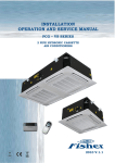
Chapter 2 work principle
2.1. Principle introduction
Picture 2-1 is the spread structure of our IDrive series medium voltage variable frequency drive
system. Take 10kV system as an example; IDrive series medium voltage variable frequency
drive adopts Superposition of series for power unit. This system mainly consist by input part,
power change part , check protection part and control part.
2.1.1. Input part
The input part of our IDrive series medium voltage variable frequency drive is mainly consist
of three part: input switch, control cabinet, input transformer. Input insulated transformer is used
to separate input AC high voltage into 3 x N group( this chapter N is unit series)AC low voltage
and send to relevant 3 x N power unit and supply electricity for N pieces independent power unit.
Between the input primary and secondary winding and the input of each secondary winding group
there keeps an relative phase-difference.
18
2.1.2. Power unit part
Power unit part is mainly consist of 3 x N pieces power unit. Every power unit adopts three-phase
bridge non-control rectifier method to rectify input low-voltage AC to low-voltage pulsating direct
current and then through capacity wave filtering and finally become middle DC.
Middle DC transmit inverter circuit which consist of four IGBT. i.e. power unit full bridge inverter
circuit. Through the switch control of IGBT to realize the status output of power unit output
voltage and PWM exchange. IDrive series medium voltage variable frequency converter has fully
considered the IGBT protection for overvoltage, over-current situation.
2.1.3. Detection and protection
IDrive series MV Drive has fully considered each component’s detection and fault protection in
design which conclude as below;
1. Input voltage detection which is used for judging input over-voltage, under-voltage, or phase
loss.
2. Middle DC voltage detection which is used for judging the damage of re-generate voltage and
capacitor.
3. Input current amplitude detection which is used for judging the equal of the output over-current
and load.
4. Transformer’s temperature detection which is used for protecting transformer from over-load.
5. Power unit’s temperature detection which is used for protecting Power Electronics component.
6. Loads working condition detection( Part model) which mainly is the detection signals of output
pressure of water-pump, output wind pressure of fan that contribute to form responsible automatic
closed-loop control.
7. Bypass cabinet ( Optional ), we mainly have power unit bypass and control, whole machine
bypass and control etc. When power unit occur fault or problem or whole machine occur fault or
19
problem, bypass cabinet will protect system from damage and not influence the continuous
working of production..
2.1.4. Control part
IDrive series control part mainly consist of master controller, PLC, human-computer
interface, upper computer, communication interface.
Master controller is the core part of whole machine. The speed protection of whole machine,
quick diagnosis of fault, the control of working status of inverter, the control of data calculation
and output which is all proceed by master controller. The master controller communicate with
power unit through optical fiber which is used to control the working status of each power
electronics in power unit. And in contrary, the working status of each power electronics in power
unit through optical fiber transmit to master controller for relative management.
Upper computer( Part model ) is mainly used for comprehensive monitor of whole machine’s
operation, the man-machine interface of user, parameter setting, system fault diagnosis etc.
Human-computer interface is consist by industrial touch panel which is used for operation
parameter setting, the operation status, the real-time monitor of unit and the fault record’s
indication and information check for our medium voltage frequency drive.
2.1.5. PLC
In IDrive series we adopt PLC to realize the electric control of equipment. Function mainly
include: equipment electricity, various assistant machines’ working status, equipment remove,
equipment bypass etc.
2.2. Main circuit
IDrive series adopt the topology structure of superposition series of power unit. Among
voltage level as 10kv, we adopt the superposition series of 9 units as indicated by below
picture2-3.
20
Insulated transformer is dry transformer which adopts strong air-cooling fan and ‘Y’ type
connection achieved by primary side direct connect with inlet wire medium voltage. Secondary
winding as extended delta connection. Between secondary winding there is certain
phase-difference.
Phase angle=60° / each phase unit.
Secondary winding supply power to power unit. The phase-difference between winding is
determined by the quantity of power unit and the level of inverter voltage.
The quantity of power unit 6kv is 15(18)pieces, 10kv is 24(27) pieces. The voltage of power unit
is promoted through wave superposition series and three phase output ‘Y’ type connection, neutral
point suspension and thus to get required adjustable frequency three-phase medium voltage power
for electric motor.
21
Take 10kv series 8 power unit series as an example, we can get (8)~(0)~(-8) total 17 different
voltage level. At the mean time of enhancing voltage level, each level voltage amount decreases a
lot and it has reduced dv/dt for motor insulation damage and also reduce a lot of the harmonic
wave of output voltage. Below picture is the actual output voltage wave of 5 power unit series.
2.3. Control system
Control system is consist of controller, PLC and human-man interface to accomplish
operation, fault alarm handle, indication and back-up copy. Controller is consist of 4 pieces of
optical fibers plate, 1 piece of interface plate, 2 pieces of sampling plate, 1 pieces of master
control plate and 1 pieces of extended plate. Controller is to accomplish system status collection
and power unit control etc. Of which adopt optical fiber technique between power unit’s
communication, reliable separation of low-voltage and high voltage, fast speed communication,
high anti-interference performance which has enhanced system reliability. PLC is mainly to
accomplish power system control and user’s site technical standard interface; human-man
interface is mainly to accomplish system itself control interface and indication status, full English
operation interface and also we equip with upper computer software to realize networking control
for user. Picture 2-6 is the logic illustration of control system.
22
2.4. Power unit
IDrive series power unit’s function principle as indicated by picture 2-7. ‘ AC-DC-AC’
single-way( one-way ) inverter structure. Short called ‘H bridge’ which is mainly formed by
rectifier bridge, electrolytic capacitor and IGBT. Through SPWM control IGBT inverter thus
output single-way AC; modularization design, every power unit is the same which is easy for
maintenance. Adopting three-phase low-voltage AC input, signal through three-phase non-control
bridge full wave rectifying by rectifier and then through electrolytic capacitor wave filtering and
finally goes to single-phase inverter circuit. This inverter circuit consist of 4 pieces of IGBT which
is formed as ‘H’ bridge structure.
Power unit through optical fiber receiving from master controller controlled signal which is
used for controlling 4 pieces of IGBT switch rule. I.e. At the output of every unit to get 0V, + Ud
( Ud is the amplitude of one power unit’s DC.) total 3 levels. Bringing every output phase power
unit of IDrive in order series( The output A1unit connects with the output A2 unit, And so on,
finally connecting the output of A1, B1, C1 three units as midpoint of IDrive).i.e. To realize the
output three-phase AC sine wave by level superposition at the output of every phase. There is an
over-current protection electrical component( instant fuse)at the input terminal of rectifier circuit.
If every power unit’s average input voltage is 690v. After rectifying and wave filtering, unit’s
direct current is 975v, 4 pieces of IGBT in each unit can divide into two group. That is: upper left
and lower left interlock. Upper right and lower right interlock. When upper left and lower right
breakover, the output voltage between two ends of U, V is +975v. When lower left and upper right
breakover, the output voltage between two ends of U, V is -975v. When upper left and upper right
breakover at the same time or lower left and lower right breakover at the same time, the output
voltage between two ends of U, V is 0v. At this time, due to every IGBT all parallel connection
with continuous free-wheeling diode. Positive and negative direction current all can free circulate
and thus at this moment equal as UV two ends short circuit. Picture2-8 is the actual output wave
of a single power unit.
23
Chapter 3
Component Composition
3.1. Introduction
The main composition of IDrive series as picture 3-1 indicated:
Cooling fan:
Select German-made air-cooling fan, powerful heat dissipation function, high reliability and long
life-span.
Phase-shifting transformer cabinet:
1. No pollution to power grid and effectively restrain power grid side harmonics( correspond with
IEEEE519-1992 regulation) which helps remove the bear of common-mode voltage for electric
motor.
2. Easy use, direct connect with user’s grid and no need any wave filter device and power element
compensation device.
Power unit cabinet:
1.Wide range adaptability, power unit superposition series method, perfect sine-wave output,
24
basically can meet every motor and cable.
2. High reliability, long-life span, high function drive circuit, speed and accurate protection,
excellent heat dissipation design, good working condition for power component.
3. Easy maintenance and installation, exquisite circuit layout and structure layout. Small volume
and light weight.
Control Cabinet:
1. High precision control, fast speed management-high quality 32-bit floating point processor,
equipped with SDRAM and FLASH memory technology.
2. Wide range adaptability, standard industrial interfaces and Ethernet, standard Modbus,
Profibus-DP, TCP/IP agreement.
3. Easy operation-full color screen and simple, optimized PC software.
3.2. Transformer cabinet
Transformer cabinet is used for installing isolated transformer and assistant component. As
indicated by picture 3-2, mainly include:
Transformer cabinet itself
Insolated transformer
Top air-cooling fan
Isolated transformer side wind blow air-cooling machine.
Transformer temperature control device.
Input current detection device.
Transformer cabinet air-cooling machine control
Transformer cabinet protection circuit.
As indicated by picture 3-2, transformer cabinet equip with phase-shifting transformer supplying
power unit three-phase power. In the door of transformer cabinet equip with temperature control
device for dry transformer which is used for transformer temperature alarm and over-heat
protection. At the inside door of cabinet equip with position switch for the alarm when cabinet
door open. At the top of transformer cabinet equip with Centrifugal fan and at the bottom of
transformer cabinet equip with wind-blow air-cooling fan with one at the front of winding and the
other one at the back side of winding.
Transformer is fixed with base as a whole by screw which is easy for transportation and
installation. Cabinet hand ring is only used for hoist transformer cabinet and can't be used for
hoisting whole cabinet include transformer cabinet. When whole cabinet need hoist, it must
through forklift hole or through transformer hoist hole.
Regarding 3kv and 6kv IDrive, Secondary winding area is at the front right side of transformer
connecting with three-phase input cable of power unit. Regarding 10kv IDrive, Secondary
winding area is at the front right and back left side of transformer connecting three-phase input
cable of power unit. Binding post should one by one match the cable mark. IDrive’s three-phase
25
input and output high voltage is from bottom( Through trench ) or side( Through underground )
into the back of transformer. The inlet wire of input power is at the upside direct goes to
transformer. Output is at downside goes out from power unit. Charging power for motor shall
adjust in accordance with the motor’s rotation direction. After connecting well of Inlet high
voltage cable, it must fix with transformer or cabinet.
3.3. Control/unit cabinet
Control/unit cabinet is used to install control system, power unit and it’s assistant component.
Power/unit cabinet as indicated by picture 3-3. Control/power cabinet is mainly consist of below
part;
Controller
UPS( Uninterrupted Power Supply )
PLC controller
Human-man interface
Power unit
Detection accessory
Voltage detection board
Control transformer module
Output current HALL component
Output voltage detection board
Primary wiring room
26
Secondary wiring room
Centrifuge air-cooling fan
Main component and function introduction:
1. Control cabinet: Mainly consist of control part and power unit part. Of which control cabinet is
mainly consist of main controller, PLC, human-man interface to accomplish all kinds of system
control, protection, fault alarm solution, indication and user connector etc.
2. Unit cabinet: Mainly consist of power unit, HALL current sensor etc. Power unit is installed
and fixed with guideway through 2 screws which is key part to realize frequency converter and
power superposition.
3. Current sensor, input and output current of sampling system which is used for various system
control and protection.
4. Air-cooling fan install at the top of cabinet and cooperate with air-duct. Cool air flows to power
unit through cabinet’s window filter layer and take the heat generated by power unit back to rear
air-duct and then through top centrifuge fan evacuate hot air outside the unit cabinet so to ensure
system working on the proper environment.
5. Dustproof filter net install at the window of cabinet door which is used for blocking dust
coming into the power unit.
6. Interlock protection install at position switch of inside cabinet. It sends out alarm when cabinet
is open
27
Take 10kv/1250kw standard product as an example to brief introduce the system composition:
1. Cabinet room, at the front side of cabinet these are controller, PLC, power switch etc. User’s
secondary terminals is also arranged in control room.
2. IDrive’s rated input/output voltage is 10kv, Power unit’s rated voltage is 690kv. Each phase 8
power unit series. Unit adopts front and back arrange method. Each front phase inside cabinet has
2 units. Take A phase as an example, from right to left there is A1 and A2. At the back of
Unit/Control cabinet each phase 6 units. Same from right to left arrange that is A3, A4, A5, A6, A7,
A8. Same phase 8 units are in series by copper bar or cable. And the first unit of three phase is
short connected as the center point of ‘Y’ type connection. Eighth unit of three-phase is right the
three-phase output high voltage of IDrive.
3. Power unit is installed at guideway which is fixed by two M8 screws. Air-duct is in the center
of cabinet. Cool air flows through front and back cabinet filter layer and all the way up to unit heat
radiator and takes away heat generated by power unit to middle air-duct and then through top
centrifuge fan evacuate heat outside the cabinet. Outside of cabinet door install with filter layer
which is used to block dust coming into power unit cabinet. Inside cabinet door install with
position switch which is used for cabinet interlock. It will send out alarm when door is open.
3.4. Master controller
Picture 3-4 Master controller board structure picture.
Master controller include optical fiber board, master control board, signal board, connector board,
sampling board and master controller board. Picture 3-4 indication, Regarding detail introduction
please kindly check chapter 2 working principle.
28
3.5. Power unit
Picture 3-5 Power unit actual picture
Power unit ( short for unit ), as indicated by picture 3-5 which is installed in power unit
cabinet. All units have same electric and mechanical parameter which is exchangeable. Unit’s
three-phase input connects with the secondary winding of main transformer also with fuse for
current protection. Output is single-phase, superposition series output. Mainly include below
component;
Rectifier bridge
Electrolytic capacitor
IGBT( Insulated Gate Bipolar Translator )
Unit control board
Equal resistance
Absorption capacitor
Fuse
Connecting copper bar, wire and insulating material.
After unloading the fixed screws between unit and guideway, input cable, input copper bar
and optical fiber connector, it will fully separate unit from unit cabinet and take it down from
guideway.
The step of unit installation is just opposite. Put unit into guideway and slightly push forward
it to limiting position and tighten screws. After connecting well with input cable and output copper
bar and then plug in optical fiber connector.
After the power off of our IDrive, unit still exist dangerous voltage or strong heat which can cause
29
serious accident. So please must wait at least 15 minutes after LED turned off. And then you can
unload optical fiber connector and separate unit. If you need to operate unit inside, you shall
only proceed after capacity fully discharged.
3.6. Human-man interface
Human-machine is installed on cabinet door which is consist by touch screen( 7.9” backlight
industrial screen )that be used to accomplish all kinds of system control, system status indication
of IDrive’s parameter such as current, voltage, power, running frequency and also to accomplish
over-load alarm, over-current for motor etc. Protect indication positioning and history fault
memory and inquiry. Monitor has 7 types of screens;
1. System status screen
2. Function set up screen
3. Parameter set up screen
4. Fault record screen
5. Operation record screen
6. Time set up screen
7. Unit monitor screen
Picture 3-6 indicated the main picture of human-man interface which mainly concludes status
instruction and operation selection. Regarding the detail description of human-man interface
please kindly see’ Chapter 5 Human-man interface’
30
Indication light
Only by IDrive occur relative status, indication light will be show up on main screen. In regular
situation it is hidden.
1. First yellow‘medium voltage indication light’, light on means IDrive is inputting with medium
voltage.
2. Second green‘running indication light’ ,light on means IDrive’ is running.
3. Third red ‘ fault indication light’ ,light on means serious fault occur. IDrive will stop running
and automatically switch off medium voltage. Only after fault solved it can continue to press
medium voltage. Light shining means slight fault occur will not affect IDrive continue to run but
we need to check the reason of fault and remove fault.
Urgent stop button:
When IDrive or on-site occur urgent situation, or urgent need to cut off IDrive’s high voltage
power, under this kind of situation please press urgent stop button. When IDrive is under detection
and maintenance, urgent stop button must be pressed so to avoid high voltage electric shock.
3.7. Bypass cabinet
In actaul practise, bypass cabinet is often being applied. Include bypass cabinet and switch cabinet
which is cooperating use with IDrive. The function of bypass cabinet is to put motor into power
frequency grid when IDrive occur fault so to ensure the continuity of production and also to
enhance system reliability.
There are basically two types of cabinet: Manual bypass cabinet and automatic bypass cabinet.
Width is about 2cm.
The suggestion of the install position for bypass cabinet: 6kv general bypass cabinet arrange at the
left side of IDrive. 10kv general bypass cabinet arrange at the right side of IDrive. Or because of
space and position limitation, arrangement and suggestion could be different but need to clarify in
technique agreement.
Picture 3-7 indicate main circuit with bypass cabinet. When system allows temporary stop, manual
bypass cabinet is adopted through operating personnel proceed switch. Manual bypass cabinet has
three knife-switches. QS21 and QS22 is double knifes double heads swith which is to ensure the
power of power frequency will not direct deliver to output terminal of IDrive.
31
Picture 3-7 manual( left) and automatic ( right ) bypass cabinet one circuit diagram.
When system does not allow machine halt, automatic bypass cabinet is the only option. It’s switch
process automatically realized. Automatic bypass cabinet has three vacuum contactors. Of which
KM2 and KM3 must interlock so to ensure the power from power frequency unable to direct
deliver to the output terminal of IDrive. Automatic bypass cabinet generally equip with isolating
switch. Isolating switch can help IDrive isolated from high voltage power when motor is running
under power frequency which is easy for IDrive maintenance and repair.
User’s primary cable( Power inlet wire and motor outlet wire) generally enters from the bottom of
bypass cabinet. The primary cable between bypass cabinet and IDrive adopts soft wire
arrangement in the inside of cabinet.
When adopting manual bypass cabinet, IDrive and power cabinet electric lock. When adopting
automatic bypass cabinet, IDrive is interlock with inlet wire contactor KM1 in bypass cabinet. The
output of IDrive can supply power for 2 electric motors through change-over switch which can
enhance the utilization ratio. When motor is one use and one standby or two motor’s working
condition is similar, you can adopt this proposal. Chang-over cabinet has 2 types of configuration
which is manual change-over or automatic change-over. The width of change-over cabinet is all
1meter which installed at right side of IDrive.
3.8. Other optional item
Power unit bypass function: When unit fault occur, it can offer protection.
Upper IPC( Industrial Personal Computer): To realize network control, real-time monitor the
status of IDrive.
Upper monitor software: To realize network control, real-time monitor the status of IDrive.
32
Chapter 4 Installation, Storage and wiring
4.1. Introduction
This chapter mainly introduce how to install and wiring IDrive and also the required procedure in
the process, techniques and relative attention events.
4.2. Check and accept event
Check and accept process
1. Check shipment’s list to see whether all equipment is right and complete.
2. Check the possible damage during transportation
3. If occur transportation damage, you shall claim compensation from transportation company.
4. Very important! Before install IDrive, you must read thoroughly and carefully and make sure
you understand the content of installation/
5. Attention! Wood block may use to support structure and unit during transport, so please kindly
remove before installation.
4.3. Transportation and storage
Transportation:
1. IDrive series is suitable for highway, railway, sea shipment.
2. IDrive series mainly has two means of transportation
1) Whole body transport, transformer cabinet, power unit cabinet and each top fan and fan hood as
a whole body for shipment.
2) Separate body shipment: transformer and it’s heat dissipation fan and fan hood as a whole body,
power unit cabinet and top heat dissipation fan and fan hood as a whole body and separately for
independent shipment.
Storage:
Please follow strictly our storage rules for IDrive which regulated in manual‘ safety event’ .
Because environment element affects IDrive’s reliability and long life-span in a large degree. So
right storage can avoid equipment lost function in advance and also help the afterwards normal
operation.
33
4.4. Transport means
Transport rules:
1. Whole body transport IDrive does not allow the re-separation of transformer cabinet and power
unit cabinet for transportation.
2. Separate body transport IDrive need independent handle, re-group and wire arrangement for
usage.
Transport method
1. Hoist and Chain hoist
2. Forklift
3. Spincycle
4. Roller wheel
4.4.1. Hoist and Chain hoist
The best way is to use rope pass by under hole and lift by hoist. As indicated by picture 4-1;
The key of hoist lifting is the length and strength.
The rope must long enough to ensure hook1.2meters up from the top cabinet which can avoid
cabinet deformation.
If the distance is not enough, a support wood block must be used. The rope strength must
support the weight of IDrive.
When using rope for hoist, please be attention that the rope must be fitted properly on forklift
hole.Try best to match hoist center with IDrive’s gravity center.
Picture 4-1 When using rope for hoist, please be attention for the gravity of IDrive and rope length.
34
Picture4-2 When using rope hoist, if rope length is not long enough, a support block is needed.
Picture 4-3 wrong rope hoist method.
4.4.2. Forklift
When using forklift, forklift must bear relevant weight. The prong length of forklift shall no less
than 1 meter. Width shall no more than 19cm. Thickness no more than 5.7cm. The distance
35
between prong must adjustable between 0.7m to 1.8m. When the length of IDrive is too long, two
forklifts can be applied to finish the job in cooperation.
Please be aware that do not let forklift hurt the surface of cabinet. We suggest to use wood block at
the corner of prong r as a protection for cabinet surface. Picture as 4-4
4.4.3. Spincycle
When using spincycle, it must be put cabinet’s under base of front and back that is outside of
forklift hole. Picture as 4-5.
The requirement for Spincycle, diameter must no less than 5cm, length no less than 1.22m.
Distance no more than 45.7cm.
Picture 4-5 the usage method of spincycle.
36
4.4.4. Roller wheel
Roller wheel is the most simple method. Many roller wheels lay side by side on floor. And
then cabinet is put above. Circulate moving roller wheel to realize transportation. The distance
between roller wheel shall less than 45cm. Picture 4-6.
Picture 4-6 is the use method of roller wheel.
As for small installation space and we can comprehensively use above mentioned methods.
4.5. Requirement for on-site installation
IDrive’s on-site must clean, flat, dry and easy for maintenance.
Heat dissipation: Cool air comes into from filter net of IDrive and flows to transformer, power unit
etc. Due to axial flow fan installed on the top of cabinet dissipates heat outside cabinet through
air-duct. So regarding installation space, the air ventilation and quantity shall be taken into
consideration.
Floor: The on-site floor required plain and flat. If the surface of on-site is not flat, the cabinet
shape of IDrive will change which will lead to cabinet malposition or unable to open switch
cabinet.
Protection: equipment inside the cabinet or partial components are not water-proof and
wind-proof. So necessary protection is needed. If inverter is temporarily being put outside, heater
must be used inside cabinet so to avoid condensation. If the time is very long, protection cover
shall be put above like plastic paper or canvas. These protection is very critical to ensure IDrive’s
safety and completeness.
37
Picture 4-7 single side maintenance installation picture
Picture 4-8 double sizes
maintenance installation picture
38
4.6.Cabinet fasten and grounding
IDrive series main circuit and control cable’s inlet and outlet connector normally locate in side or
bottom of transformer cabinet.( Subject to random picture ); The requirements for IDrive as
below:
Installation requirement:
1. Suggest the minimum length of cable ditch shall add 1 meters each at left and right under the
foundation of all cabinet’s length which is easy for wiring and maintenance.
2. The IDrive’s base on the ditch adopts10# channel steel( When IDrive’s rated output power >
1600kw, it shall adopt 16# channel steel. Above 4000kw adopts 18# channel steel). The specific
details shall follow the actual weight of IDrive.
3. When installing, we must leave certain room for the top,
size shall follow above picture’s definition.
front and back of cabinet. Specific
4. As for double size maintenance IDrive, the distance of equipment’s back size shall no less than
1000mm. Single maintenance, suggestion size shall no less than 600mm.
Wiring requirement:
1. When ground installation, we Suggest adopts welding method to fix with base. If the base
is already grounding, the IDrive cabinet grounding can achieve through welding with base. Under
this situation, we should ensure enough welding spot and the quality of welding spot. We suggest
the welding spot shall no less than 8.
2. If base is not grounding, then the grounding of IDrive cabinet will need to realize by
additional grounding cables.
4.7.Medium voltage cable fasten and grounding.
Cable making:
The input and output of IDrive cable is normally armoured cable which is very hard and not
easy curved. In order to make wiring easy and beautiful, we should not follow the same length to
make cable but rather design a wiring radian in advance. Measure and estimate the stripping
length of each core wire and leave certain extra length. By this way, the input and output medium
voltage cable will be very beautiful. Picture as 4-9 indicated.
39
Picture 4-9 medium voltage fasten and grounding.
Cable grounding
1.The shielding layer of medium voltage input and output cable must grounding at site of
IDrive. Normally grounding realized in transformer cabinet by the help of grounding bolt.
2. If IDrive is along with ‘ bypass cabinet ‘, grounding of IDrive’s medium voltage input and
output cable in shielding layer can be realized in bypass cabinet.
Picture 4-10 bolt grounding and inverter grounding picture.
40
4.8 User wiring
Standard wiring picture
IDrive series standard wiring picture as indicated below;
Cable option
1. Main circuit suggesting cable selection chart: Chart4:1( Suitable for general type series, not
include special and big power type)
41
Frequen
cy
Rated
current
Terminal
Function
symbol
Input Output
A.B.C
Screw
specification
Restrain
Torque
Cable size
M10
18.0~23.0
22~100
(mm2)
(A)
25~27
U.V.W
60
Ground
wiring
PE
M5
2.0`2.5
5.5~14
45~60
Input Output
A.B.C
M10
18.0~23.0
22~100
U.V.W
60
Ground
wiring
PE
M5
2.0~2.5
5.5~14
75
Input Output
A.B.C.
M10
18.0~23.0
22~100
U.V.W
80
Ground
wiring
PE
M6
4.0~4.9
5.5~22
100~125
Input Output
A.B.C.
M10
18.0~23.0
38~100
50/60Hz
U.V.W
125
Ground
wiring
PE
M8
8.9~10.8
5.5~38
150~180
Input Output
A.B.C.
M10
18.0~23.0
38~100
U.V.W
180
Ground
wiring
PE
M8
8.9~10.8
22~60
200~250
Input Output
A.B.C.
M10
18.0~23.0
60~100
U.V.W
250
Ground
wiring
PE
M10
18.0~23.0
22~150
280~300
Input Output
A.B.C.
M12
31.5~39.5
150~325
U.V.W
400
Ground
wiring
PE
M12
31.5~39.5
60~200
350~400
Input Output
A.B.C
M12
31.5~39.5
150~325
42
U.V.W
400
Ground
wiring
PE
M12
31.5~39.5
60~200
600
Input output
A.B.C
M10
31.5~39.5
150~325
M16
78.5~98.0
150~325
U.V.W
600
Ground
wiring
PE
2. Control cable recommendation selection chart,picture4-2
Function
Specification
Screw
specification
Restrain torque
(N x m)
Cable size(mm2)
Analog quantity input
and output
Strand
wire
shielded
/
/
0.5~1.5
Analog quantity input
and output
Insulated PVC
armoured
cable(CVV)
/
/
1.0~2.5
/
/
0.5~1.5
/
/
4.0~8.0
Communication cable
Control power cable
600v
Insulated
PVC armoured
cable(CVV)
Main circuit wiring:
All user main circuit input wiring terminal is in transformer cabinet. While output terminal could
be different according to different types.
1. Main circuit standard wiring picture, picture 4-12
43
2. Main circuit input terminal, chart 4-3;
Terminal symbol
Signal name
specification
A
Main circuit A phase input
Main circuit AC three-phase
B
Main circuit B phase input
C
Main circuit C phase input
input
Voltage: 3kv/3.3kv, 6kv/6.6kv,
10kv/13.8kv;
Frequency: 50Hz/60Hz
3. Main circuit input terminal, chart 4-4:
Terminal symbol
Signal name
Specification
U
Main circuit U phase output
Main circuit AC three-phase
V
Main circuit V phase output
W
Main circuit W phase output
ouput:
Voltage:
0~(3kv/3.3kv,
6kv/6.6kv,10kv/13.8kv);
Frequency:0~(50Hz/60Hz)
Picture 4-13 Main circuit input wiring terminal reference.
Picture4-14 Main circuit output wiring terminal reference.
44
Control wiring
1. Control circuit standard wiring picture, picture 4-15
45
2. Control wiring terminal row is centered in control cabinet, chart 4-5;
Terminal
row
Function
specification
XT1
Control power
Three phase four wire system: AC 380V/20A,
50/60Hz
XT2
User
order
XT3
Analog
input
XT4
IDrive’s
order
XT5
Analog
output
symbol
side
input
quantity
output
quantity
DC24V dry contact or AC220V dry contact signal
DC4~20mA or 0~10V signal
DC24V dry contact or AC220V dry contact signal
DC4~20mA or 0~10V signal
Terminal definition:
1. Control power input terminal, chart 4-6:
Type
Terminal fit
Signal name
Specification
Input
XT1-a
Control power a phase input
XT1-b
Control power b phase input
Control power: AC three-phase
input:
XT1-c
Control power c phase input
XT1-n
Control power 0 wire input
46
Voltage: 380V/20A
Frequency: 50Hz/60Hz:
2. Analog quantity terminal, chart 4-7
Type
Signal name
Signal
level
electrical
Input
Speed(Frequency)
DC4~20Ma/0~10V
Order
Closed
response
loop
Order
Spare
Output
Running frequency
Output current
DC4~20mA/0~10
V
DC4~20mA/0~10
V
Terminal
symbol
Function instruction
XT3-3
Speed(Frequency)order input
XT3-4
Grounding
XT3-PE
Shield ground
XT3-1
Closed-loop response signal order
input
XT3-2
Grounding
XT3-PE
Shield ground
XT3-5
User definition
XT3-6
Grounding
XT3-PE
Shield ground
XT5-1
Running frequency output
XT5-2
Grounding
XT5-PE
Shield ground
XT5-3
Output current output
XT5-4
Grounding
XT5-PE
Shield ground
Terminal
symbol
Function instruction
3. Digital quantity terminal, chart 4-8
type
Signal name
Signal
level
Input
Urgent stop
Terminal input:
XT2-1
Urgent stop IDrive order
1) AC 220V/5A
XT2-2
Public earth wire
2) DC 24V/5A
XT2-3
Start IDrive order
3) DC 48V/5A
XT2-4
Public earth wire
XT2-5
Stop IDrive order
XT2-6
Public wire
XT2-7
Restore IDrive fault/ alarm order
Start
electrical
Stop
Restore
47
XT2-8
Public earth wire
XT2-9
IDrive corotation running order
XT2-10
Public earth wire
XT2-11
IDrive’s reverse rotation operation
order
XT2-12
Public earth wire
-----
User optional signal
XT2-13/15
User definition
XT2-14/16
Public earth wire
ENC
Control input of IDrive terminal
XT4-1
Subsection user side high voltage
order
XT4-2
Public earth wire
XT4-3
Slight fault situation output order
XT4-4
Ground earth wire
XT4-5
Heavy fault situation output order
XT4-6
Ground earth wire
XT4-7
Operation status output order
XT4-8
Ground earth wire
Stop
XT4-9
Stop status output order
High voltage ready
XT4-10
Ground earth wire
XT4-11
High voltage joint up IDrive order
XT4-12
Pubic earth wire
XT4-13
Remote or local control IDrive status
order
XT4-14
Ground earth wire
XT4-15
Permit user high voltage put into
IDrive order
XT4-16
Ground earth wire
Corotation
Reverse rotation
Terminal input:
1) AC 220V/5A
2) DC 24V/5A
DSC signal
3) DC 48V/5A
Spare
Encoder signal
High voltage
Separating
brake
Normally-open
contact
relay
output:
1)DC 220V/5A
2)DC 110V/5A
Output
IDrive slight fault
Normally-open
contact
relay
output:
IDrive heavy fault
1) AC 220V/5A
2) DC 24V/5A
Running
Remote/Local
High
voltage
switch
on
permission
48
Power frequency/
XT4-17
frequency
conversion
Power frequency or frequency
conversion running status order
XT4-18
Ground earth wire
Spare
XT4-19/20
User definition
XT4-21/22
Ground earth wire
Attention
Transformer primary winding has a group of + 5% voltage tap to compensate power voltage.
When product leaves factory the tap is 0. The transformer’s original secondary winding voltage is
changing according to normal exchange rate. Except un-normal situation, please don’t change the
tap position.
Under some circumstance, independent power unit may separating transport with unit cabinet.
After installation please confirm the right connection of input cable wire with optical fiber cable.
Such as cabinet separating transportation, please confirm the right connection of unit with optical
fiber between controllers.
4.9 electromagnetic compatibility installation instruction
This instruction introduce the four measures shall be taken into consideration to realize
electromagnetic compatibility when install perfect no-harmonic wave inverter. That is: Grounding,
shielding, filtering and wiring. Through these measures will reduce IDrive’s electromagnetic
below rated amount. And also in this way IDrive has realized electromagnetic compatibility.
49
4.9.1. Grounding
IDrive provide grounding point to ensure cabinet connected with protection area. Grounding point
is grounded inside the IDrive’s cabinet, picture as symbol
which is located in nearby A.B.C
power input cable and the connecting terminal of U.V.W. motor output cable. Each part is all
connected inside by yellow, green color wire or black wire winded with yellow or green tape.
All user’s connecting cable of protection area shall be short as much as possible and also shall
meet all local’s grounding installation requirement IDrive series we suggest protection area’ single
point grounding’ to avoid to cause grounding circulation. All protection area connection need to
check during routine maintenance.
4.9.2. Shielding
The purpose of shielding is to protect harmful Radio Frequency electromagnetic radiation
interrupt IDrive’s system normal working. And at the same time reducing itself to interrupt other
equipment running. Because inside of cabinet there are lots of power switch component and
micro-controller that will generate electromagnetic radiation. Thus, It is important to handle well
of shielding measure when design cabinet and connecting input & output cable.
The cabinet of IDrive has been exquisite designed and test which can effectively resist interruption
of electromagnetism. All input and output cable all need shielding which can enhance the
electromagnetic compatibility. The cabinet shell itself is actually effective shielding body which
can further enhance electromagnetic compatibility.
1. IDrive’s cabinet, cable shielding layer, motor shell these three shielding bodies must connected
effectively.
2. Cable shielding layer is not allow breakage.
3. The connection between shielding body must maintain low-resistance in MHz frequency
segments.
4. We suggest to use specialized connector to achieve shielding layer low-resistance connecting.
4.9.3. Wiring
1. Control and signal wire, try best to use all analog and digital control wire by shielding cable. If
there is no shielding cable, we can use twisted pair cable instead. If using twisted pair cable, try
best to make twisted pair close to cable terminals. Try best to avoid using public earth wire
between different analog signals.
2. Ensure the separation of digital signal wire and analog signal wire. Prohibit wiring high and low
voltage signals, large current, small current and low voltage weak signal together. If possible,
using double shielding cable to enhance further electromagnetic compatibility.
3. Control and signal cable must separate with power cable.
4. Control and signal cable slot must away from power cable slot at least 200mm.
5. If control and signal cable has to go through power cable, we must try best to keep angle close
to 90. Picture 4-18 indicated.
50
Picture 4-18 recommendation cable separating method.
6.Power(grid/motor) cable, we suggest all input and output high voltage cable add shielding layer
to reduce radio frequency radiation to ensure electromagnetic compatibility. Cable shielding layer
need consist by non-magnetism metal group and keep the electric consistency on all cable. The
function of banded shield is much better armoured cable and non-banded cable layer, like one
shielding layer can also restrain electromagnetic radiation. But the effect of resist-radiation is not
better than bended shielding layer.
7. When install cable we must comply with cable factory’s recommendation of biggest tensile and
minimum curvature diameter requirement.
8.Other cable shielding layer, power, control or signal shall not connect with motor cable shielding
layer. Otherwise it will generate very high electric noise.
9. We recommend all IDrive’s grid input and motor output cable shielding layer shall connect with
protection area only at one side. When adopt armoured cable, it must correctly connect with
terminal. Armour connect with terminal in 360 angle. Terminal connects with installation board in
360 angle. And then installation board effectively connects to protection area.
10. Serial communication cable, signal transmission standard( RS232, RS485, Ethernet etc.) and
agreement standard( Profibus-DP, Modbus, TCP/IP etc.) will recommend suitable cable type.
Please comply with relative standard to implement.
11. Encoder cable---Pulse encoder may direct connect with motor rotor without through electric
insulation. This situation mus ensure no insulated bearing being bridged and cause to failure. The
same as cable types, we must strictly follow the recommendation of encoder supplier. We must
ensure consistency from encoder to IDrive’s cable and should not cut off in the middle.
51
4.10. Insulation method.
When all wiring work finished, we should also measure the insulated resistance of relative circuit
which shall comply with the requirements of chart 4-5.
Chart 4-5 insulation requirement chart
Circuit nominal voltage
Megger leve
Insulated resistance
Low-voltage(< 50VAC< 120VAC)
250VDC
> 0.25MΩ
Medium
120VAC)
500VDC
> 0.5MΩ
1000VDC
> 1.0MΩ
voltage(<
High voltage(>500VAC)
50VAC,>
52
Chapter 5, Human-machine interface
5.1. Main picture
IDrive series possess a very simple and easy-operation human-machine interface which installed
at the control cabinet board of IDrive. Picture 5-1 is indicated as default state of main picture.
Picture 5-1 IDrive series main picture
Date indication:
Indicate output frequency( Hz ) of IDrive and output current( A)
Operation area:
IDrive’s frequency set up and start, stop, restore and urgent stop operation.
Frequency set up:
1. Input box set up method, Frequency interval increase and decrease. Under the input box method,
user can direct input frequency range from 0.00Hz to 50.00Hz which can locally adjust IDrive’s
running frequency. Under the method of frequency interval, user can press enhance key, such as
frequency interval set up as 5Hz, input frequency will increase 5Hz based on original frequency.
User can press decrease key, such frequency interval set us as 5Hz, input frequency will decrease
5Hz based on original frequency.
2. IDrive’s start, stop, restore and urgent stop all operated by press keys. Of which start and stop
53
operation interlock. Restore and urgent stop interlock. After IDrive start, we can proceed stop and
urgent stop operation. After IDrive stop, we can proceed start and restore operation.
Alarm indication
1. Yellow or red flashing indication light which will be hidden when IDrive is under normal
function.
2. When alarm happens, yellow indication light will turn on.
3. When fault happens, red indication light will flash.
4. When press down indication light, it can change to fault record picture.
Picture 5-2IDrive series status picture
Data indication:
1. IDrive AB phase, BC phase, CA phase input voltage and output voltage.
2. IDrive A phase, B phase, C phase input current and output current.
3. Transformer A phase, B phase, C phase temperature.
Data and status indication:
1. IDrive input power, output power and unit cabinet temperature.
2. IDrive status
5.2.
IDrive status instruction
Status is 0
Serial
number
(Black
indication)
Status is 1
Paraphrase
Paraphrase
( Red indication)
1
Probit switch on
IDrive is unable
to put on voltage
Permit switch on
IDrive is able to put on
high voltage.
2
High voltage not
ready
IDrive get high
voltage but can
not start
High
ready
IDrice get the high
voltage and can start.
3
Locally
IDrive is in local
working status
Remote
IDrive is under remote
working status
4
Power frequency
IDrive’s bypass
cabinet is in the
working position
frequency
conversion
IDrive’s bypass cabinet
is in the working
position of frequency
54
voltage
of
power
frequency
conversion
5
Closed-loop
IDrive’s control
way
is
closed-loop
Open-loop
IDrive’s control way is
open-loop.
6
Converse
IDrive is under
Corotation
IDrive is under normal
rotation
converse rotation
7
Stop
IDrive
running
8
HMI
is
communicating
with PLC
9
PLC
is
communicating
with DSP
stop
running mode.
Running
IDrive is running
Human-machine
interface
is
normal
communicating
with PLC
HMI
is
off
communicating
Human-machine
interface is un-normal
communicating
with
PLC.
PLC is normal
communicating
with
main
controller
PLC
is
off
communicating
with DSP.
with PLC
PLC
is
un-normal
communicating
with
main controller.
Running time indication:
1. IDrive single running time and accumulated running time.
Picture change-over button
Chart 5-3, picture button function
Main picture
Click can return to main picture
Lower level picture
Click can get into unit status picture
5.3. Unit monitor picture
Picture 5-3 indicated as ‘default status’ unit monitor picture.
55
Picture 5-3 IDrive series unit monitor picture
Unit indication area:
1. It can reflect power unit three phase U,V,W total 24 status. According to the indication of
different system series, when there is no unit, default all is 0.
2. Respectively indicate every unit’s temperature, DC generatrix voltage, normal/fault status,
stop/running status.
If one of unit happens fault, normal status will change to fault status and this unit will indicate
fault information.
Picture change-over button
Chart 5-4, picture change-over button function
Main picture
Click it and it will return to main picture
Upper level picture
Click it and it will return status picture.
5.4 Parameter set up picture
Picture 5-4 indicated as ‘ default status’ of parameter set up picture.
56
Picture 5-4 IDrive series unit monitor picture
System parameter set up:
Click button you can speed up time, slow down time, stop frequency, frequency hopping
point 1, frequency hopping point 2, frequency hopping 3 and adjust frequency interval. If click
speed up time button, it will pop out input dialog box like picture 5-5.
Picture 5-5 IDrive series’ parameter set up picture.
User can input number in dialog box. Press confirm button to set up parameter. Press cancel button
can close the window and parameter will not effect.
1. When press down manual button, PID adjustment set up transfer to manual mode. Picture as
indicated by 5-6.
2.Under manual mode, user need to set up goal-number. Kp number, Ki number, Kd number.
Observe feedback number and to get to know IDrive’s adjustment status.
Picture change-over button
Chart 5-5, picture change-over button function
Main picture
Click to return to main picture
Lower level picture
Click to enter into parameter check picture
57
5.5. Parameter check picture
Picture 5-7 indicated as ‘ default status’ parameter check picture.
Picture 5-7 IDrive series parameter check picture.
Parameter check area:
1. Indicate IDrive 37 running parameters, user can only check but can not edit.
2. Parameter check area can divided into 3 sub-main pictures. Click parameter set up sub-main
picture you can check all 37 running parameters.
Picture change-over button:
Chart 5-6. Picture change-over button function
Main picture
Click can return to main picture
Upper picture
Click can enter into parameter set up
picture
Parameter
picture
check
sun-main
Click can enter into parameter check
picture
1. Picture 2. Picture, 3.Picture
58
5.6. Fault record picture
Picture 5-8 indicated as ‘ default status’ fault record picture
Picture 5-8 IDrive series fault record picture
Fault record indication:
1. Indicated happened alarm, fault and disappeared alarm and fault.
2. Indicate alarm and fault happen time and close time. If alarm and fault is not removed, it will
not indicate close time. If alarm and fault is removed, it will indicate close time which indicates
alarm and fault is removed in recorded time.
Alarm and fault is arranged in time order. At the same time each alarm and fault has
corresponding detailed information which is easy for user to analyze fault reason.
Fault record inquiry.
Click button, it will pop out time range set up dialog box. Picture as 5-9 indicated;
59
Picture 5-9 IDrive series fault record inquiry picture
1.Select all disc-saving data, all alarm and fault since fault record area indication touch screen is
running.
2. Select near time, set up the time length such as 10 minutes. Fault area indicate the time length
after the present moment. Such as alarm and fault happen within 10 minutes.
3.Select fixed time can click drop-down box, you can choose alarm and record happened at
present day, present week, present month, previous day, previous week, previous month. You will
also need to set up time division point. Such as set up 0 means everyday 0 as time division point.
4. Select appointed moment disc-saving date which shall set up the amount of second, minute,
hour, day, month, year to check time setted up alarm and fault.
Picture change-over button:
Chart 5-7, picture change-over button function
Main picture
Click return to main picture
60
5.7. Operation button
Urgent stop:
IDrive control cabinet,” Red mushroom-like urgent stop button’
. When IDrive is happening
serious damage, you can press this button immediately. IDrive’s controllable high voltage switch
will turn off. It can avoid equipment damage and personal injury in the shortest time. When the
fault of IDrive is removed, you can spin urgent stop button to restore. This button is effect at any
circumstance.
Local/remote operation switch:
IDrive control cabinet,“Local / remote change-over switch”,
, When change-over turn to
left,( Local position ), IDrive is only for human-machine interface.Remote box or the start of DCS,
stop, restore, frequency adjustment are all non-effetc.
When switch turn to right side( remote position ), IDrive operation is only for remote box or
DCS. At the moment human-man machine operation is non-effetc.
Remote control box( Optional )
IDrive can equip with remote control box, it has start, stop, restore, urgent stop, corotation, reverse
rotation, frequency adjustment and multi-segment selection function which can indicate IDrive’s
running frequency, speed, motor rotation speed, motor current information etc.Remote control box
can control signal through the connecting of hard connecting wire with IDrive’s secondary input
terminal.
61
Chapter 6 Start and debug
6.1. Introduction
This chapter talks about the necessary required procedure for the success start of IDrive
series. From eye check before power on to complete test with high voltage motor., These check or
test will proceed in order during the different stages of start process. This chapter will introduce it
in a separate way. Every paragraph introduction all contains a series of independent procedure
which is for engineering staff or user to put into practice. Some chapter contain several charts to
record parameter set up, test data or every error and deviation of relative expectation.
Attention
When high voltage part is filled with electricity, please never switch off system power of heat
dissipation. Otherwise, cooling system will stop working. Thus may cause system heavy over-heat
and unit damage.
Dangerous
Before debug, please make sure to switch off IDrive’s input power and abide by relative
operation regulations such as right interlock and alarm board etc.
Dangerous
Even though we turn off the high voltage breaker and control power switch, IDrive cabinet still
may remain possible existence dangerous high voltage( For example, unit inside capacitor will
store power);
Please follow strictly ‘ Safety event’ to proceed.
62
6.2. Debug process and instrument & equipment
6.2.1 Debug process
Please follow below process to start and debug
Start----->eye
check
before
power
on------->converse
power
on---->simulation
running----->Running without motor------>Running with motor------>done.
6.2.2. Required instrument & equipment
Start debug with below instrument & equipment
Serial
No.
Name
Basic specification
Quantity
1
High
electroscope
Rated voltage>10kV, with sound and light
indication
1 piece
2
Insulated glove
Rated voltage > 10kV
1 pair
3
Insulated shoes
Rated voltage >10kV
1 pair
4
Megger
>1kV
1 piece
5
Grounding
meter
>10Ω
1 piece
6
Digital multi-tester
DC maxi. voltage: 1000V
1 piece
voltage
resistance
AC maxi. Voltage: 1000V
Maxi. Resistance: <5000MΩ
Accuracy > 0.5
7
Digital clamp meter
AC current effective value: > 100A
1 piece
Accuracy > 1.0
8
infrared
temperature
measurement gun
-35℃~ +500℃
1 piece
9
Three-phase
voltage regulator
capacity: >6kVA
1 set
63
Input voltage: 380V
Input voltage no less than: 0~400V
10
Digital
Double
oscilloscope
channel
insulated
Width>200Mhz,
1:1000(>100A)
( Optional )
oscilloscope,
Current
1 set
Probe:
High voltage probe: 1: 1000(>1000V)
11
power
analyzer
quality
(Optional )
12
Non-contact
Power, harmonic, power factor, voltage
interruption,
1 set
voltage dip, voltage swell
laser
tachometer
Measure distance: >2m
1 piece
Rotation range: >3000rpm.
(Optional )
6.3 Eye check before power on
IDrive must proceed eye check before power on. According to chart 6-2 verify system whether fit
for design.
Chart 6-2 eye check before power on
Procedure
Description
1
Verify IDrive input voltage whether is confirm to IDrive specification. The rated
input voltage of IDrive is recorded at the nameplate of inside cabinet.
2
The rated output voltage in IDrive’s nameplate shall conform to motor nameplate
rated voltage picture as 6-1.
3
Control voltage( Low voltage )must match the rated control voltage of IDrive.
4
Please verify the rated power of motor nameplate with the rated power of IDrive’s
nameplate.
Like left reference picture
64
6-1.
5
1. Confirm input-side neutral point of transformer whether is right.
2. Connect with 0 position of transformer’s three group winding
+5% position, transformer secondary voltage lower 5%;
0 position, transformer secondary voltage is normal.
-5% position, transformer secondary voltage increase 5%.
6
Confirm power plug of air-cooling fan is right and tightly connected with power
plug seat of transformer cabinet and power unit cabinet. And the rotation direction
is in conformity with motor pointed direction.
7
Check all connecting and wiring inside of IDrive and make sure they are all well
tightly fastened. And ensure all electric connecting point( include main circuit )
marked with fastening mark.
8
Confirm there is no cabinet damage and also do not have serious outside paint
comes off. If any, Check the back of damage position or component underneath,
cable and the completeness of other material.
9
Check all cable whether has breakage or damage. Ensure they are not naked by
friction or unappropriate transportation.
10
Check all terminal row, component, unit and signs of other components or labels
whether exist.
65
If it not comply with design, please contact supplier.
11
Ensure all protection barrier exists and is right installed.
12
Confirm the right connection of control power with main circuit power and fit for
local electric regulation
13
Verify all rightness of user wiring and tightness.
14
When install outside cable of IDrive, it must comply with standard safety working
process and local laws and regulations. The protection distance between low
voltage cable and other cable must fit for national standard GB/T 11022-2011.
15
Confirm special wire that has follow the design requirement to use as shielding
cable which is aimed to ensure electromagnetic compatibility.
16
High voltage cable and low voltage cable must strictly separate and ensure at least
30cm safety distance which is aimed to guarantee electromagnetic compatibility.
17
Confirm IDrive is right and reliable grounding according to local regulation and
ensure system
single point grounding. Grounding point is at inside of cabinet marked by signal
of right picture.
Note: If any above-mentioned check is different or un-normal from design. Please contact supplier in time.
6.4. Converse power on test.
Below procedure is to test below function:
Check the completeness of input transformer
Check the completeness of unit control board
Activate electrolytic capacitor in the DC generatrix of power unit.
Be ready for IDrive’s simulation running
66
Chart 6-3 IDrive converse power on test
Procedure
Description
1
1) Switch off phase-shifting transformer input side inlet wire or high voltage switch.
Switch off IDrive’s output to motor side outlet wire or high voltage switch.
2) Put user side three-phase four wire system 380VAC capacitor > 6kVA, a,b,c
three-phase cable through three-phase voltage regulator right connect to control
cabinet assist 380V three phase terminal block ‘ XT1’
2
Connect IDrive control power , start UPS (Uninterrupted Power Supply), wait for
the finish of IDrive initialization.
3
Open touch screen picture first to status picture, and first check HMI to PLC
communication status and PLC to DSP communication status whether connected.
And then check transformer’s three phase temperature, unit cabinet temperature
whether is normal, and then move to unit monitoring picture and wait for conserve
power on while observing every unit’s generatrix voltage, unit temperature, and unit
working status.
4
1) Getting through the input power of three-phase 380VAC of voltage regulator and
adjust the output voltage of voltage regulator slowly up to 50V and maintain 10
minutes. Observe and record all unit’s generatrix voltage. And also compare the unit
generatrix voltage to given reference. When some unit ‘s generatrix voltage is far
smaller than given reference. Cut the power off to check relative unit.
2) Continue to slowly turn up output voltage of voltage regulator to 150V and
maintain 10 minutes. While observing and record all unit’s generatrix voltage.
3) Continue to slowly turn up output voltage of voltage regulator to 250V and
maintain 10 minutes. While observe and record all unit’s generatrix voltage.( When
voltage regulator output voltage turn up to approx. 200V, high voltage powered on
relay KA2 will appear off and on repeatedly which is normal)
4) Continue to slowly turn up output voltage of voltage regulator to 380V and
maintain 10 minutes. While observing and recording all unit’s generatrix voltage.
5) During the converse power on process, pre-charge function will not be activated.
5
Power on finish check:
1) Unit drive board power‘ Green ’ indication light whether is lightened.
2) Human-man interface power unit DC generatrix voltage function interface,
voltage and temperature whether is normal.
3) Whether it has fault alarm indication. When press human-man interface restore
button whether it can remove relative fault and alarm and make the system ready.
67
6.5. Frequency simulation running test
Below procedure is to check IDrive control system’s running whether is under right operation and
protection.
Chart 6-4 IDrive simulation running
Procedure
Description
1
1) Start
After converse power on finished, Under the circumstance that IDrive has no fault
and alarm, press start button and confirm. The output frequency of human-machine
interface started to change and according to speed up time set up from start
frequency to settled up frequency. At the same time, the green operation light on
control cabinet board is on.
2
2) Stop
After frequency running up to settled frequency, please press stop button and
confirm. Output frequency decrease from running frequency to stopped frequency,
output frequency change to 0Hz. Green running indication light of control cabinet
board is off.
2
Fault simulation is to check control system whether is normal work. Fault
simulation needed as below:
1) entrance guard
Open and close power unit cabinet and transformer cabinet door in order and
check the indication and fault light status of human-man interface and record the
results.
2) Fan fault
Switch off I1.0, I1.0 input point indication light is off. And then connect I1.0
manual restore, fault remove and record the result.
3) dual power switch
a. Switch off breaker Q1, KA21 indication light is off. KM21 switch off,
KA22 indication light is on. KM22 pull-in, control system is supplied with
380VAC by transformer secondary side.
b. Switch on breaker Q1, A21 indication light is on. KM21 pull-in, KA22
indication light is off. KM22 switch off, control system is supplied 380VAC by
user side. And record the result.
4) Unit and main control communication
Random unplug 3 optical fibers at control cabinet , human-machine interface
indicate relative unit communication fault. Fault indication light is on, and plug
68
back optical fiber and press restore button. Fault is removed. And record the result.
3
Switch off converse power on 380VAC. After waiting 15 minutes and then switch
off IDrive’s control power. And restore to factory-out status.
6.6 IDrive without motor test
Below procedure is to check IDrive running situation( without motor )
Chart 6-5 IDrive without motor test
Procedure
Description
1
Without motor high voltage operation( Include manual bypass cabinet);
1) Switch off user-side high voltage switch cabinet and shake-out breaker. Switch
on grounding knife brake to closed position.
2) Withdraw the output cable from bypass cabinet to motor side.
3) Close breaker Q1 and Q2 and get through control power. And start UPS and
wait for the finish of IDrive initialization.
4) Open insulated switch QS2in bypass cabinet to IDrive input status. QS1 switch
to close brake status( Note: Prohibit operating insulated switch with high voltage )
5) Confirm and close all high voltage cabinet.
6) If we need to put in precharge function, we can manual close breaker Q3.
System will control pre-charge process. After the finish of pre-charge, human-man
interface will prompt switch off breaker Q3 and then permit high voltage being
closed.
7) Switch grounding knife brake of user-side high voltage cabinet to separate
position. And shake out breaker to running position. And then close user-side high
voltage cabinet.
2
1) Change IDrive’s simulation running mode to normal running mode.
Verify acceleration time, deceleration time, VF curve parameter, unit series,
compensation voltage, adjust amplitude adjustment factor parameter.
69
3
1) Confirm board indicating right input voltage. If input voltage too high or too
low, implement below adjustment procedure.
2) If input voltage too high and so it need to come down. IDrive factory-out using
0 tap, transformer secondary voltage is normal proportion voltage.
3) If input voltage too low or too high, connecting transformer neutral point to -5%
or +5% tap.
4
Set up frequency 5Hz, start frequency. Let IDrive running under 10Hz, 15Hz,
20Hz, 25Hz, 30Hz, 35Hz, 40Hz, 45Hz, 50Hz. Record relative output voltage and
current wave shape.
5
Test urgent stop:
1) Confirm user-side high voltage switch cabinet‘opening coil’ concatenate IDrive
control cabinet terminal XT4-1. Switch user-side high-voltage switch cabinet high
voltage breaker to test position
2) Press down urgent stop button on the cabinet door board. User-side high voltage
switch cabinet can effectively opening.
3) Under the running circumstance of IDrive, press down ‘Urgent stop’ button,
IDrive will automatically block output. And at the same time, user-side high
voltage switch cabinet opening, indication light on the cabinet door will turn on.
4) Clockwise spin’ opening’ button to pop-up position. Press down ‘ restore
button’, fault is removed. Indication light is off.
6
High voltage power on operation without motor( Include manual bypass cabinet )
1) Stop IDrive running
2) Switch off user-side high-voltage switch cabinet and shake-out breaker.
Switch grounding blade brake to closing position
3) Wait for 15 minutes. Electrolytic capacitor within power unit cabinet
finished discharging.
4) Change insulated switch QS1 within bypass cabinet to opening position.
5) Switch off breaker Q1 and Q2, switch off control power and close UPS.
70
6.7. IDrive running test with motor
Below procedure is to check IDrive running situation( With motor )
Chart 6-6 IDrive with motor test
Procedure
Description
1
High voltage power on operation with motor( Include manual bypass cabinet )
1) Switch off user-side high voltage switch cabinet, shake-out breaker, switch
grounding blade brake to closing position.
2) Connect the cable from bypass cabinet to motor-side output cable in a right and
reliable way.
3) Close breaker Q1 and Q2 and get through control power, and start UPS. Wait
for the finish of initialization of IDrive controller.
4) Move insulated switch QS2 inside bypass cabinet to IDrive input status. QS1
switch to closing status. ( Note: Prohibit operating insulated switch in bypass
cabinet with high voltage)
5) Confirm and close all high voltage cabinet
6) If need to put pre-charge function you can hand closing breaker Q3, system will
control pre-charge process. After the pre-charge finished, human-machine interface
will prompt switch off breaker Q3 and permit high voltage being joined.
7) Move the grounding blade of use-side high voltage switch cabinet to separating
position. And shake out brake to running position. Close user-side high voltage
cabinet
2
1)Enhance speed up/ down time:
Speed up time: 60.0 seconds or longer
Speed down time: 60.0 seconds or longer
2)Set up stop frequency:
Stop frequency: Recommend 20%.
3)Set up Frequency hopping points
According motor resonance point set up range, you can set up at most 3 segment
4)Set up frequency modulation interval:
FM interval: recommend 5Hz.
71
3
System filled with power, it may occur alarm and fault, press down ‘ Fault restore’
button on human-machine interface to restore and remove. If you are unable to
remove. Please check ‘ fault remove and maintenance’ chapter content to remove
fault and ready for test. If you can not remove, please contact supplier directly.
4
To drive motor with 10Hz. Observe the rotation direction whether is right. If it’s
not right, please change-over the rotation direction order position of
human-machine interface’ work set up word’
5
Repeat IDrive without motor test’ Procedure 4’:
6
Running with high voltage motor ( Include manual bypass cabinet )
1) Stop IDrive operation
2) Disconnect user-side high voltage switch cabinet, shake-out breaker, move
grounding blaze brake to closing position.
3) Waiting for 15 minutes for the discharging finish of electrolytic capacitor within
power unit.
4) Move insulated switch QS1 in bypass cabinet to opening position.
Switch off breaker Q1 and Q2, switch control power and shut UPS.
72
Chapter 7 Function Character
7.1. Flying start
Flying start can also become rotation start. i.e. To start under motor rotating status. IDrive series
do not need motor speed sensor. The detection of motor rotation normally adopts power off
detection.
By the frequency produced by remanence of induced electromotive force, IDrive according to this
frequency and relative output voltage to steady adjust rotating motor and to get expected running
status. Picture 7-1 is the flying start wave picture and time order picture.
7.2. Sudden power off and on start
Sudden power off and on start function is main to ensure load normal operation under given
frequency when circuit occur sudden drop or power off.
Due to the unsteady quality of on-site running grid or other on-site factors, it will occur power
sudden drop or off status, IDrive adopt bi-directional inverter technique. When detect grid
electricity fall, it will start invert charging to ensure IDrive’s normal function under short period of
time. And to satisfy working situation requires higher reliability. Sudden stop time in functional
parameter can be set up by user. And at same time to set up start method as flying start.
7.3. Load torque limitation
IDrive series has fast dynamic response ability which is specially suitable for occasion
required harsh acceleration and deceleration time. Under the fast acceleration/ deceleration time
and at same time ensure current and voltage limitation safely output and restrain load torque and
73
drive motor fast, and safely. Picture 7-2 actual measurement of maxi. current voltage limitation
and sequence chart.
7.4. Torque promotion
For the constant torque load, if we keep V/F=constant, then we can at the same time ensure
air-gap flux, output torque and over-load capability no change. But under low frequency, due to
the converse electromotive force is relatively small, we can ignore the influence of motor stator
resistance. At this time, we can relatively enhance motor terminal voltage to compensate the
influence of stator voltage drop. This method we called Torque promotion.
Under power frequency, the resistance of motor for voltage drop is low. When IDrive running,
the motor’s resistance is in proportion increase with the frequency decrease. Thus increase relative
difference between V and E
Adopt V/F control IDrive, when set up V/F as constant adjustment. With the decrease of
frequency, motor Magnetic flux will decrease, Motor torque will also decrease. When frequency
drops down very low, motor torque will also become very low and very hard to drag constant
torque load motor and even hard to start. Thus we need to increase the output voltage according
when under low frequency running. IDrive series torque promotion parameter can be set by
manual which is more flexible fit for different working situation.
7.5. Brake control
IDrive adopt direct current to brake. When braking, IDrive’s output frequency is 0. Charging
asynchronous motor stator winding with direct current. Motor stator form up constant magnetic
field.Brake torque is form by rotor drove by transmission machinery cutting stator static magnetic
74
field. The mechanical energy of transmission system can transfer to electric energy and consume
in the rotor circuit of motor through rotor’s heat dissipation.This kind of energy consume brake is
used in control occasion required accurate motor stoppage or the brake for motor free
rotation( such as fan) caused by external force before IDrive system start. DC brake two main
parameters: DC brake frequency f and DC brake current I which can through manual set up.
7.6. Open-loop control
Under close-loop running mode, user can set up and adjust the expectation of controlled
parameter( like flow, temperature, voltage etc). IDrive can automatically adjust output frequency
according to the actual measured value of controlled parameter thus to control the motor rotation
and output power. That is controlled parameter is ultimate close to expectation value. We adopt
PID control method during the process of automatic adjustment. Normally we set up Integrating
factor D as 0. You can also call PI adjustment.
7.7. Upper machine monitor( Optional )
For the convenience remote monitor and parameter set up, IDrive can equip with upper machine
software( Optional), upper machine software main function as picture 7-3 which can set up
IDrive’s running parameter, real-time indication, record running status and history record check.
75
Chapter 8 Fault remove and maintenance
8.1. Introduction
IDrive series have through on-site running test and can running for a long time without fault.
This chapter front half part is to introduce IDrive series normal fault and pattern of
manifestation, behind half part is to introduce fault handle method and IDrive’s regular
maintenance.
Dangerous
Before check or maintain IDrive, all input power must be cut off.
Attention
Only professional staff through professional training can maintain IDrive series.
8.2. Fault and alarm classification
Under normal circumstance, the alarm indication light and fault indication light(fault indication
light is red
, alarm indication light is yellow
) on IDrive human-machine interface and cabinet
is not on and flash. If master controller software and hardware detect fault and alarm, and then
save relative information to fault record and indicate these information on human-machine
interface, fault and alarm indication light is on and flash. Fault and alarm maybe is caused by the
fault of hardware and software.
Unit fault or alarm is detected by unit control board inside power unit. Every power unit has
independent detection circuit. Control system proceed decode, indication and save record
according to alarm or fault uploaded by unit.
Normally, Any fault will instant prohibit IDrive stop running and cut off the power supply for
motor. Some fault allow use to self define such as degrade or upgrade fault level and change
IDrive’s response method. Alarm is only for warning, indication and record. But not stop IDrive
running. IDrive fault and alarm definition see picture 8-1.
Chart 8-1‘Fault and alarm’ type and IDrive response.
Type
IDrive response
Fault
1) Block all IGBT
76
2) IDrive will stop freely
3) Fault is recorded into history fault record. See history fault record screen
4) Fault indicate on human-machine interface
5) Fault indication light is on
Alarm
1) Alarm is recorded into alarm record. See history fault record screen
2) Alarm is indicated on human-machine interface
3) Alarm indication light is on
Attention:
Restore button on human-machine interface, in IDrive stop situation(When IDrive is controlled to
stop, it is real stop when IDrive reduce speed below stop frequency), you can manual store
fault/alarm.
IDrive happens fault, save and record in order and lock save until fault is removed. It can be
removed through manual restore operation. Alarm, save and record in order not lock save. When
alarm is removed, it will remove automatically or also through manual restore.
8.3. IDrive fault and alarm
Fault and alarm instruction:
1. ‘type’ indicate fault ( F ), alarm (A) or according to definition. Both is OK(F/A)/ (A/F), (F/A)
default as fault (F),(A/F) default as alarm(A).
2. ‘configuration’ indicate fault or alarm whether permit user to change. Permit/prohibit(Y/N). I.e.
Fault degrade alarm or alarm upgrade to fault.
“ High voltage input” fault and alarm;
Chart 8-2 ‘High voltage input’ fault and alarm
Serial
No.
Fault
indication
Type
configur
ation
Fault reason and solve measure
1
Input
loss
F
N
Reason:
phase
1) Input phase loss
Measure
1) Check and confirm input three phase cable
whether is right
2) Check controller board serial 2 “ Sampling
77
board” whether is broken.
2
Input
A/F
Y
over-voltage
Reason:
1) IDrive’s input cable voltage effective value
exceed 120% of rated voltage brake value
3
4
Input
under-voltage
A/F
High voltage
power loss
F
Y
Reason:
1) IDrive ‘s input cable voltage lower 65% of rated
voltage brake value
N
Reason:
1) IDrive input cable voltage effective value is
lower than rated voltage brake value. This
parameter can set up, default as 20%.
Measure
1) Check and confirm three-phase cable whether is
right connected.
2) Confirm human-machine interface‘power cut
voltage’ set up whether is right
At same time check three-phase input voltage
whether is right.
3) Check controller board serial 2’sampling board’
whether is broken.
‘ Motor/ IDrive output’ fault and alarm
Chart 8-3 ‘ Motor/ IDrive output’ fault and alarm
Serial
No.
Fault
indication
Type
configur
ation
Fault reason and solve measure
1
Encoder
without signal
A
N
Reason:
( Optional )
1) Software detect no encoder signal. This fault may
caused by the encoder broken or encoder terminal
broken
Measure:
1) Encoder hardware broken
78
2) Encoder transmission cable broken
3) Check controller board 4‘expansion board’
whether is broken.
2
Motor
over-heat
A/F
Y
Reason:
1) When motor running current exceed‘overload
alarm brake value’ trigger; Default 1.1 times
over-current 10 minutes.
Measure:
1) Check‘ pber-load alarm brake value’ parameter
whether is right set up.
2) Check load motor whether is over-load under
long time working
3) Check the heat-dissipation system whether is
normal.
3
IDrive
over-load
A/F
Y
Reason:
IDrive output current exceed rated output current
125%, and running time over 1 minutes. Parameter
can set up, alarm is on immediately when default
parameter is 1.25 times over current. Alarm is not
lock save. Successive alarm exceed 1 minutes will
upgrade to fault.
Measure
1) IDrive real running over-load, check motor load
status
2) Check human-machine interface indication
parameter‘ over-load brake value’ and ‘over-load
time’ whether is right.
3) Check Hall sensor whether is under normal
operation
4) Check controller board serial 3‘sampling board’
whether is broken
4
IDrive
over-current
F
N
Reason
1)When IDrive output current exceed rated output
current 180%, instant protection will on.
Over-current protection has 2 level brake value.
Parameter can set up. Default is 1.8times over
79
current 3s or 1.5 times over current 10s.
Measure:
1) IDrive real running current, check motor load
status
2) Confirm human-machine interface indication
parameter‘over-current
brake
vale
1’
or
‘ Over-current brake value 2’ set up whether is right
3) Check HALL sensor whether is right
4) Check controller board serial‘Sampling board’
whether is right.
5
Output phase
open circuit
F
N
Reason:
1) Software detect IDrive to motor’s output phase
open circuit
Measure:
1) Check IDrive to motor side all connection
whether is right
2) If there is bypass cabinet, check bypass cabinet
part whether is working un-normal
6
7
Torque
amplitude
limiting
A
Torque
amplitude
limiting speed
down
A
N
Reason
1) Under acceleration too fast or load sudden
change condition, it cost output torque exceed
torque setted maxi.reference. Default value: 120%
rated torque 1 minute.
N
Reason:
1) Under the function of amplitude limiting
regulator, regulator output frequency continue lower
than system frequency set up value. Default value:
30 minutes.
Measure:
1) check load condition
2) Check IDrive torque amplitude limiting
parameter set up whether is right.
80
Control power fault and alarm:
Chart 8-4 control power alarm and fault
Serial
No.
Fault
indication
Type
configu
ration
Alarm reason and solution measure
1
+ 15V
A
N
Reason
Power fault
1) IDrive HALL sensor power fault
Measure
1) Check + 15V switch power output whether is
un-normal.
2) Check the connection from HALL sensor
power to controller ‘ sampling board’ whether is
un-normal.
2
24V
A
N
Power Alarm
Reason
1) Controller supply power voltage lower than 9V
or exceed 27V;
Measure
1) Check controller 24 V switch power output
whether is un-normal.
2) Check 24V supply power cable connection
whether is un-normal.
Air-cooling system fault and alarm
Chart 8-5 air-cooling system fault and alarm
Serial
No.
Fault
indication
Type
configu
ration
Fault reason and solution measure
1
Air-cooling
fan fault
F
N
Reason
1) Caused by heat dissipation fault on the top of
transformer and power unit cabinet.
Measure
1)Check connection of fan power and power
supply whether is un-normal.
2) Check air-cooling panel whether is stuck by
sundries( Other things )
81
3) Air fan hardware component damage.
System control fault and alarm
Chart 8-6 system control fault and alarm
Serial
No.
1
Fault
indication
Entrance
guard fault
Type
configu
ration
Fault reason and solution measure
F/A
Y
Reason
1) IDrive and power unit cabinet is opened
Measure
1) Close IDrive and power unit cabinet, fault is
removed.
2) IDrive entrance guard switch is damaged.
3) Check entrance guard switch to PLC detect
cable whether is disconnected.
2
Transformer
over-temperat
ure alarm
A
N
Reason
1) Phase-shifting transformer work temperature
over 120℃
Measure
1) Check phase-shifting transformer temperature
sensor whether is damaged.
2) Check transformer cabinet’s filter whether is
blocked by sundries.
3) Phase-shifting transformer bottom or cabinet
top heat dissipation fan whether is un-normal.
4) IDrive working environment temperature
whether is too high.
3
Transformer
over-temperat
ure fault
F
N
Reason
1) Phase-shifting transformer working
environment exceed 160℃.
Measure
1) Same as above-mentioned‘Transformer
over-temperature alarm’
4
Unit cabinet
A
N
Reason
82
Over-temperat
ure alarm
1) Unit cabinet working temperature exceed 60℃.
Measure
1) Check unit cabinet temperature sensor whether
is damaged.
2) Check unit cabinet filter whether is blocked up
3) Unit cabinet top heat dissipation fan whether is
normal working.
4) IDrive working temperature whether is too
high.
5
Unit cabinet
F
N
Over-temperat
ure fault
Reason
1) Unit cabinet working temperature exceed 70℃.
Measure
1) Same as above-mentioned‘unit
over-temperature alarm’
6
User 380
F
N
Power loss
cabinet
Reason
1) IDrive control system 380V power loss
Measure
1) Check user 380V power connection whether is
normal.
2) Check detection contactor KM1 working
weather is normal.
Communication fault and alarm:
Chart 8-7 communication fault and alarm
Serial
No.
Fault indication
Type
configu
ration
Fault reason and solution measure
1
Human-machine
interface
communication
fault
A
N
Reason
1) Human-machine interface is failed
communicate with PLC
Measure
1) Check communication cable of
human-machine interface and PLC 485 whether is
normal.
83
2) Two types of 485 connector hardware damage
and change relative hardware.
2
Controller
communication
fault
F
N
Reason
1) PLC is failed to communicate with controller.
Measure
1) Check communication cable of PLC and
controller whether is normal
2) Two type of connectors hardware is damaged
and change relative hardware.
3
Optical fiber
F
N
communication
upper fault
Reason
1) Controller is unable to receive signal from unit
control board.
Measure
1) Check the connection of controller and unit
control board relative channel interlink optical
fiber whether is normal.
2) Check working of unit check board whether is
right
3) Check controller whether is normal
4
Optical
communication
F
N
Down fault
Reason
1) Unit control board is unable to receive signal
from controller
Measure
1) Same as above-mentioned‘Optical fiber
communication upper fault’
8.4. Unit fault and alarm
8.4.1. Unit fault information
Unit fault is caused by circuit of unit control board of every power unit. Controller board receive
these fault signals through Optical plate. Chart 8-8 instruction for quick search and unit fault
diagnosis.
84
Chart 8-8 unit fault
Serial
Fault
No.
indication
Type
1
Phase loss
configu
Fault reason and solution measure
ration
F
N
Reason
1) One or several unit fuse blow
Measure
1) Confirm the reason of fuse blow( If require )
repair damage unit and change fuse.
2
Over-heat
A
N
Reason
1) Unit temperature exceed alarm limited value.
Default alarm limited value is +85 ℃.
Measure
1) Check air-cooling system status
2) Check motor load status
3) Change damage unit control board.
3
Drive
F
N
Reason
1) IGBT over-current or short circuit, maybe
IGBT damage or unit control board damage.
Measure
1) Check motor load status
2) IDrive acceleration time too fast which can
adjust human-machine interface‘ acceleration
time’ parameter.
3) Change damaged unit control board.
4) Change damaged IGBT, please contact with
supplier.
4
Unit
fault
power
F
N
Reason
1) Unit control board control power supply
un-normal. 5V or 15V power un-normal. Unit
control board power module damaged.
Measure
1) Change unit control board and contact supplier,
5
DC generatrix
F/A
N
Reason
85
undervoltage
1) Unit generatrix voltage lower than alarm valve
value.
2) Unit control board detection voltage damage.
3) Adjust human-machine interface‘ DC
generatrix under-voltage parameter set up whether
is right.
Measure
1) Check input voltage whether is too low.
2) Change unit control board and contact supplier
8
DC generatrix
over-voltage
F/A
N
Reason
1)Unit generatrix voltage exceed alarm limited
value, normally because IDrive reduce speed too
fast
2) Unit control detection board is damaged.
3)Adjust human0machine interface‘ DC
generatrix over-voltage’ parameter set up whether
is right.
Measure
1) Check input voltage whether is too high.
2) IDrive speed down too fast which can adjust
human-machine interface‘deceleration time’
parameter
3) Charge unit control board and contact supplier.
8.5. Unit fault maintenance
Phase loss fault
Caused by power unit front side fuse blow. Check fuse and change damaged fuse. And problem or
damaged components.
Drive fault
Transistor PN junction carrier cause higher junction resistance, transistor will lead to bigger
voltage reduce and consume which cause component damage in advance. Unit Drive Board
possess the function of detection component break over and voltage reduce, close IGBT when
86
fault occur. This fault may caused by flaw unit control board or noise from unit control board.
Before power unit changed, we shall find out exact reason for fault occur. Otherwise, it may
happen un-predictable situation.
DC generatrix under-voltage fault:
It is occurred when generatrix voltage reduce to the valve value settled by detection circuit on unit
control board. Maybe it is caused by low input high voltage coupling with load required big
current. Or maybe caused by sudden overload.
Power unit any AC power fuse blow can cause this fault. Check unit fuse and see whether it is all
right.
Damaged unit control board sometimes demonstrate wrong indication. Change flaw or damaged
component.
DC Generatrix over-voltage fault:
1) Adjust human-machine interface ‘ deceleration time’ parameter and proper extend IDrive
deceleration time.
2) Unit control board detection circuit is interrupted or damaged. Change unit control board
3) Check unit input voltage and phase-shifting transformer output voltage whether is normal.
Over-heat fault
1) Check unit cabinet top fan whether is running normal and right.
2) Check filter net whether is blocked.
3) Check IDrive indoor temperature whether is un-normal.
4) Ensure every cabinet closed, heat-dissipation right installed to ensure good air-cooling flow.
5) Check unit control board whether is broken.
Communication fault
1. Check optical fiber link, if there are any problem we need to change.
2. Check or change unit control board.
3. Check the connection of controller main board and optical fiber board whether is good or
damaged.
87
8.6. IDrive input protection
IDrive main control software integration possess IDrive input side un-normal detection
condition and provide protection procedure module. Fault is caused by these procedures which can
use proper interlock through output relay or serial communication to switch off IDrive’s high
voltage input power.
8.6.1. Transformer over-heat fault or alarm
The temperature of all secondary winding of transformer is monitored by two set temperature
switch( Normal closed point ). First set of temperature switch connector will open when
temperature exceed 120℃. W hile second set connector will open when temperature exceed 160℃.
When 120℃ connector switch off, it issue out ‘ Transformer over-temperature alarm’。 When
160℃ connector switch off, it issue out‘ transformer over-temperature fault’ signal, it issue out
‘ Transformer over-temperature fault’ and to make IDrive tripping.
8.7. Fault dealing process
After IDrive fault occur, user can refer to below process to proceed fault dealing.
1. Through human-machine interface check various alarm and fault.
2. Read this chapter other parts diagnosis introduction to check possible reason and solving
method.
3. If IDrive unreasonable stop and human-machine interface can not indicate, please contact
supply for after-sale service.
4. If fault dealing simple can through remote control to instruct user to finish fault dealing. If fault
dealing complicated. Supply will send out engineer to repair. And engineer will bring fault dealing
relative equipment and tools.
5. Suggest before contact supply after-sale engineer, please collect IDrive fault information as
much as possible. If try re-charging high-voltage power, after restoring fault, re-start IDrive to see
fault will occur again or try to adopt below 2 points to restore fault.
1) As for standby fault, analyse fault through adjustable unit optical fiber whether it is from unit or
main controller. And then through exchange or unit control board change to analyse fault whether
is from unit control board or unit other components.
Attention:
When component change is needed, we must check whether new and old component is the same;
After exchange unit optical fiber, IDrive is forbidden to test running. Running may cause IDrive’s
power unit damage.
88
8.8. Regular maintenance
Regular check filter net block situation. If air blow is not enough, clean filter net or change filter
net.
Regular check power unit control board dust accumulation status. If dust accumulation is very
serious, stop machine to clean. During the clean process, be attention on static protection.
If indoor install air conditioner, regular check air condition situation. Ensure indoor temperature
not exceed 40 ℃, humidity not exceed 90%.
Regular check IDrive whether has smelly or un-normal noise.
Regular check IDrive running situation( Running mode, voltage, current and speed etc.)
Regular need to discharge or recharge UPS after long time no running, which is used for
activating battery electrolyte.
When IDrive is no time no running, we need to discharge power unit fully before use it again,
which is used for activating electrolytic capacitor electrolyte.
Attention
Any damaged component disposal shall according to local regulation and requirement.
89
Chapter 9 After-sale service
9.1. Introduction
Shanghai Istech electric Co., Ltd.( Short for Istech ) customer service department provide service
according to pre-regulated service policy. Service will implement according to within Guarantee
time or over Guarantee time.
9.2. Quality ensure regulation
In order to maximum maintain our client benefit, Istech provide certain time quality ensure.
Quality regulated as below: All IDrive quality ensure time is 18 months after our product arrived
at on-site or 12 months after IDrive start running. Among which early expiry as base. Within
quality ensure time, client can have free maintenance. But for force majeure like natural disaster,
accident, wrong use and unauthorized disassemble, repair and change thus caused serious damage,
Istech will not be responsible for free maintenance.
9.3. Service type and policy
9.3.1. Basic principle
1. To help client solve problem and reduce unnecessary loss, and promote client satisfaction
as our basic principle.
2. Obey laws and rules and client’s regulation and system.
3. Istech service electrician duty range: Equipment expediting, cargo check, equipment
quality issue handle, instruct installation and debugging, participate test running and function
acceptance test.
1) Before install and debug, on-site engineer shall hand-over technique to user. Explain and
demonstrate proceeding procedure and method. As for important procedure, technician shall
confirm and read down on-site procedure, otherwise next procedure is not allowed. Through Istech
electric confirm and sign process, if problem happens due to wrong guidance of our technician,
Istech will fully be responsible.
2) On-site service technician has the right to deal with any technique and business problem
occurred on-site installation. If IDrive happen quality problem, Istech electric will slove problem
within regulated time. If Istech entrust user side to solve problem, it must approved by Istech side
and bear for relative economic loss.
90
4) Istech shall communicate with buyer for sending engineer in advance/.
5) Buyer shall cooperate with sending technician and support our service person daily
necessary, transportation and communication.
9.3.2. Start debug
Istech offer every free service for starting and debug of new installed IDrive. Debug time is
calculated from engineer arrived at on-site. If client reason cause debug delay, our company will
charge extra overtime cost.
9.3.3. On-site maintenance
Istech provide IDrive on-site fault maintenance service, service as regulated below;
All fault fits above-mentioned reason within quality ensure time, Istech will responsible for free
maintenance.
Exceed quality ensure time, if need maintenance service from Istech, the cost will relatively
charged. For detail, please contact Istech's client service department.
On-site service person is to ensure equipment safe, normal running,. Istech will send service
person to on-site and provide ‘on-site service chart’; If our plan can meet the requirement of
engineer, we will change plan chart through negotiation and free charge.
9.3.4. Ship back to factory maintenance
Istech provide maintenance service for fault happened IDrive and other components shipping back
to IDrive factory.
Within quality ensure time, this service effect is under IDrive can not maintenance on-site.
Beyong quality ensure time, user can choose whether on-site maintenance or this maintenance. If
our plan can not meet the requirement of project, we can change plan through negotiation and
charge for free.
9.3.4. Technician maintenance
Istech provide on-site or company technical training. Through training, trainee can further
understand the IDrive’s working principle and technical features, AC motor principle, frequency
transmission basic terms and IDrive regular maintenance and fault dealing etc. Additionally,
trainee will learn a certain knowledge of IDrive software control system, menu system etc.
Necessary training will improve production efficiency, maxi. improve equipment usage and realize
equipment best function. Training content and project shall be the same as the process of project.
Training time, number of people, place detail content will be confirm through two sides agreement.
This charge is for free.
91
9.3.6. Predictable maintenance and preserve.
Due IDrive possess high usage rate, long circle time and different working environment features.
Normally proceed predictable maintenance according to on-site conditions varies from 6~18
months as a circle time. If high voltage IDrive is running under harsh environment and lack of
maintenance, it will reduce equipment use time. At same time, it will also influence production
and cause unnecessary economic loss.
Istech insist on providing IDrive running rate as a key point, stressing the importance of
equipment maintenance and preserve and provide predictable maintenance and preserve service
from client benefit. This service is conclude equipment inside clean, machinery re-positioning,
circuit board clean, circuit board selection and necessary protection, system function test, old
machinery component repair and change etc. Specific information please contact Istech service
department.
9.3.7. Upgrading and function reform
If customer purchase IDrive afterwards would like to add assistive function to enhance running
stability. Such as workable technical program by extra equipping with bypass system. Upgrading
and reform process as below; Istech service department will first access customer’s require
demand, and then issue a upgrading or plan reform paper. If customer recognize Istech’s proposal
and then we will charge relative predictable service fee in advance, and then engineer will go to
on-site proceed service. Our service charge is based on ‘ surplus refund and shortage re-charge’
principle to charge final value. Regarding relative on-site detail, please contact Istech service
department.
9.4. Contact information
Address: 777 Yuegong Road, Jinshan Industrial Zone, Shanghai, China.
Postcode: 201506
Sales hot line: +86-021-67290577
Email: [email protected]
After-sale service: +86-021-37219859
Website: www.istech-electric.com
Fax No. +86-021-67290576
92