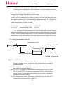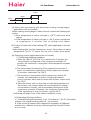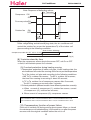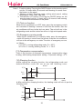
1
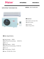
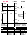
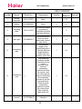
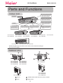
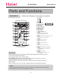
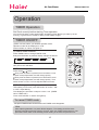
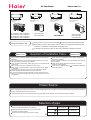
Air Conditioner Edition:2006/1/10
CAUTION
READ THIS MANUAL CAREFULLY TO
DIAGNOSE TROUBLE CORRECTLY
BEFORE OFFERING SERVICE .
SERVICE MANUAL
Air Conditioners
THIS MANUAL IS USED BY
QUALIFIED APPLIANCE
TECHNICIANS ONLY. HAIER
DOES NOT ASSUME ANY
RESPONSIBILITY FOR PROPERTY
DAMAGE OR PERSONAL INJURY
FOR IMPROPER SERVICE
PROCEDURES DONE BY ONE
UNQUALIFIED PERSON.
MODEL: HSU-12HD03/R2
HSU-
REVISION 0
Air Conditioner Edition:2006/1/10
IMPORTANT INFORMATION
MODEL: HSU-12HD03/R2
ƽҏFeatures
ƽҏComfortable: wide-angle airflow
ƽhealth air purifying
ƽquiet operation
ƽҏsuper energy efficient
ƽMain Specification
ƽCooling CapacityΚ 3500W
ƽRated Power/Current(cooling)Κ 1090W/5.2A
ƽEER: 3.21
ƽHeating CapacityΚ 3650W
ƽRated Power/Current(heating): 1010W/5.0A
ƽCOP: 3.61
ƽAir Volume(Indoor): 500m3/h
ƽPower: 1PH 220-230V~ 50 Hz
Air Conditioner Edition:2006/1/10
Safety Information
General Information
This Service Manual describes the operation,disassembly,troubleshooting,and repair of Haier Room Air
Conditioners,etc. It is intended for use by authorized servicers who troubleshoot and repair these units.
NOTE:It is assumed that users of this manual are familiar with the use of tools and equipment used to
troubleshoot and repair electrical,mechanical,and refrigeration systems;and understand the terminology
used to describe and discuss them.
Haier urges you read and follow all safety precautions and warnings contained in this manual. Failure
to comply with safety information may result in severe personal injury or death.
Related Publications
This is a base service manual,covering a range of similar models.It is intended to be used in
conjunction with the Parts Manual and Technical Sheet covering specific model being serviced.
General Precautions and Warnings
WARNING
To avoid risk of personal injury or death due to electrical shock,disconnect electrical power to unit
before attempting to service the unit.
WARNING
To avoid risk of personal injury or death due to electrical shock,DO NOT,under any circumstances,alter
the grounding plug .Air conditioner must be grounded at all times.Do not remove warning tag from power
cord.If a two-prong (non-grounding) wall receptacle is encountered,contact a qualified electrician and
have the receptacle replaced with a properly grounder wall receptacle in accordance with the National
Electrical Code.
WARNING
To avoid risk of personal injury or death due to electrical shock,grounding wires and wires colored like
grounding wires are NOT to be used as current carrying conductors.The standard accepted color coding
for ground wires is green or green with a yellow stripe.Electrical components such as the compressor
and fan motor are grounded through an individual wire attached to the electrical component and to
another part of the air conditioner.Grounding wires should not to be removed from individual components
while servicing,unless the component is to be removed and replaced.It is extremely important to replace
all removed grounding wires before completing service.
WARNING
To avoid risk of heat exposure,which may cause death or severe illness,air conditioner must be
monitored when malfunctions or shuts down.
Air Conditioner Edition:2006/1/10
CONTENTS
1.SPECIFICATION...............................................................................1
2.ACCESSORIES ................................................................................3
4.OPERATION......................................................................................5
5.ELECTRI CAL CONTROLL............................................................. 21
6.TROUBLE SHOOTING...................................................................28
7. INSTALLA TION...............................................................................33
8. CIRCUIT AND WIRING DIAGRAM.............................................42,44
Air Conditioner SPECIFICATION
1
Edition:2006/1/10
Air Conditioner Edition:2006/1/10
Model˖ HSU-12HD03/R2
Cooling Capacity˖
Rated Power/Current˖
Cooling
Max Power/Current˖
EER
Heating Capacity˖
Heating
Rated Power/Current˖
-----
Brand Mark˖
3500W
1090W/5.2A
1PH
Power
1620W/8.3A
COP
220-230V~ 50 Hz
--------
Model×Sectional Area˖
3.21
Power Cord
3650W
Refer. No.˖
Compressor
1010W/5.0A
1600W/8.0A
Compressor
3.61
--------
SANYO/CRV113
manufacturer/Type
Max Power/Current˖
50Hz
Frequency Range˖
500(poe)
Oil charge
Power/Current of
-----
R410A 800g
Type/Net Charge˖
Electric Heating˖
Operating temp. range
Additional Charge for
-7OC-43OC
Refrigerant
1350
H˖
----- g
exhausting air.
Charge if over Standrad
r/min
---g/m
Pipe Lenth
Indoor
1100
Velocity M˖
L˖
920
H˖
H˖
1000
----
Velocity H˖
----
Outdoor
Lenth×Internal/External
r/min
Capilary
Diametre
r/min
Refer No.˖
r/min
Height of rising
r/min
radiator slice
Indoor˖
Outdoor˖
r/min
Indoor Weight
Air
-----
----1.30
1.37
Net˖
7.6kg
Gross˖
10.6kg
Net˖
37kg
Gross˖
42kg
Outdoor Weight
Volume Indoor˖
(High) Outdoor˖
Capacitor of Fan Motor˖
Class of electric Shock Protection
Class of Water Proof˖
Moisture Removal˖
500
-----
3
m /h
795×265×182 mm
3
m /h Indoor Dimension(L×W×H)˖
……
ĉ
IP 24
Indoor Packaging Dimension(L×W×H)
865x272x330 mm
Outdoor Dimension (L×W×H)˖
855×331×596 mm
Outdoor Packaging dimension(L×W×H)
876×364×638 mm
1.5×10⁻³m 3/h
ij6.35/9.52 mm
liquid /Gas pipe Diametre
Refrigerant
Remote
Model˖
Controller
Refer. No.˖
H
Pipe
0010413791
mm
mm
5m
standard Lenth
Max Lenth
15
m
Remote Controller Bracket˖
-----
Lenth/Diametre of Drain Hose
4.15
MPa
Appearance˖
-----
Max. pressure at warm side˖
4.15
MPa
Climate Type˖
T1
Max.pressure at cool side˖
---
Installation Bracket Type˖
-----
Plug Type(spec.)˖
---
Ammeter spec.˖
---
Area available for clooling/heating
15-23
m
2
Dry/Wet ball(indoor)˖ 32℃/ 2 3 ć
Max.running
temperature(cooling):
Dry/Wet ball(indoor):27 /
ć --ć
Max.running
Dry/Wet ball(outdoor)˖43 ć/ 26 ć
2
Dry/Wet ball(outdoor):24℃/18℃
temperature(heating):
Air Conditioner Edition:2006/1/10
ACCESSORIES
3
Air Conditioner Edition:2006/1/10
HSU-12HD03/R2
Failure
Quality
Remark
Rate(%)
Number
Name
Refer No.
Description
1
remote
controller
0010413791
None
1
0.2
2
battery
001A4600001
None
2
0.1
0010101275
Fix mounting plate
according to
installation position
and pipe direction
001A0900011
Choose the place
that can drain
water and connect
pipe easily
1
0.1
----
The maximal
length of the
connecting pipe is
15m,the maximal
height between
indoor unit and
outdoor unit is 5m
1
0.2
3
4
5
6
7
mounting
plate
drain pipe
connecting
pipe
connecting
wire
manual
----
001A7265614
The conecting
methods include
ring terminal and
direct
terminal .Ring
terminal
connecting
method:Unscrew
the screws ,and
put it through the
ring of connecting
line ends,then
connect it into the
terminal block.
Direct terminal
connecting
method:unscrew
the screws,then
fully insert the
cable ends into.
Operation
4
*
0
*
.
1
0.2
*
1
0
Air Conditioner OPERRATION
5
Edition:2006/1/10
Air Conditioner Edition:2006/1/10
Contents
Cautions
Parts and functions
Operation
Maintenance
Trouble shooting
1
2-4
5-12
13-14
15
6
Air Conditioner Edition:2006/1/10
Cautions
The machine is adaptive in following situation
I. Applicable ambient temperature range:
Indoor
Cooling
Outdoor
Indoor
Heating
Outdoor
Maximum: D.B / W.B
Minimum: D.B / W.B
Maximum: D.B
Minimum: D.B
Maximum: D.B
Minimum: D.B
Maximum: D.B / W.B
Minimum: D.B / W.B
o
o
32 C/23 C
o
o
18 C/14 C
o
o
43 C/26 C
o
18 C
o
27 C
o
15 C
o
o
24 C/18 C
o
o
-7 C/-8 C
2. If the supply cord is damaged, it must be replaced by the manufacturer or its service agent
or a similar qualified person. The type of connecting wire is H05RN-F or H07RN-F
3. If the fuse on PC board is broken please change it with the type of T. 3.15A/250V.
4. The distance between the indoor unit and the floor should be more than 2m.
5. The wiring method should be in line with the local wiring standard.
6. After installation, the power plug should be easily reached.
7. The waste battery should be disposed properly.
8. The appliance is not intended to use by young children or infirm persons without supervision.
9.Young children should be supervised ensure that they do not play with the appliance.
10.The appliance must be installed on strong enough supporter.
11.The wiring diagram is attached inside the machine.
7
Air Conditioner Edition:2006/1/10
Parts and Functions
Indoor Unit
Test running switch(manual)
Used only for test running in cooling
when room temp. is below 16oC.
Don't use it in normal operation.
Inlet grille
Emergency switch(manual)
Used when remote controller is lost or
defective. Unit will run temporarily.
Remote signal receiver
Air filter
A beeping sound is generated when
a signal from remote controller is
received.
Vertical flap
Power indicator
Timer mode indicator
Operation mode indicator
Use remote controller to
adjust up and down air flow.
(Don't adjust it manually.)
Lights up when unit starts.
Lights up when Timer operation
is selected.
Lights up during compressor
running.
HSU-07HC03/R2
HSU-12HE03/R2
HSU-07HE03/R2
HSU-12HC03/R2
HSU-22HB03/R2
HSU-09HC03/R2
HSU-14HB03/R2
HSU-22HC03/R2
HSU-09HE03/R2
HSU-18HB03/R2
HSU-09HD03/R2
HSU-12HD03/R2
HSU-07HD03/R2
HSU-22HD03/R2
Actual inlet grille may vary from the one shown in the manual according to
the product purchased
Outdoor Unit
HSU-07HC03/R2
HSU-07HE03/R2
HSU-07HD03/R2
HSU-09HC03/R2
HSU-12HC03/R2
HSU-14HB03/R2
HSU-09HE03/R2
HSU-12HE03/R2
HSU-09HD03/R2
HSU-12HD03/R2
HSU-22HD03/R2
HSU-22HC03/R2
HSU-22HB03/R2
HSU-18HB03/R2
OUTLET
CONNECTING PIPING AND ELECTRICAL WIRING
INLET
DRAIN HOSE
8
Edition:2006/1/10
Air Conditioner Parts and Functions
Operation
Buttons and display of the remote controller.
1
1. Mode display
AUTO
COOL
DRY
HEAT
FAN
2. SWING display
3. FAN SPEED display
4. SLEEP display
5. LOCK display
6. SIGNAL SENDING
7. TIMER OFF display
8. TIMER ON display
9. CLOCK display
10. TEMP display
11. POWER ON/OFF
5
2
3
ON
OFF
A
U
T
O
4
ON/OFF
TEMP
6
7
8
9
10
11
18
MODE
FAN
MED
Used to select AUTO run, COOL,
DRY, HEAT and FAN operation
13. FAN
TIMER
Used to select fan speed LO, MED, HI, AUTO
20
14. HOUR
14
SWING
Used to set clock and timer setting.
CLOCK
15
15. SWING
21
Used to set auto fan direction.
16. SLEEP
Used to select sleep mode.
SLEEP
17. LOCK
16
LOCK
17
HI
12. MODE
19
13
LO
Used for unit start and stop.
SET
12
AUTO
Used to lock buttons and LCD
display.
RESET
18. TEMP.
22
Used to select your desired temp.
19. SET
Used to confirm timer and clock settings.
20. TIMER
Used to select TIMER ON, TIMER OFF,
TIMER ON-OFF
21. CLOCK
Used to set correct time
22. RESET
Clock set
Used to reset the controller back to
normal condition.
When unit is started for the first time and after replacing batteries in remote controller,
clock should be adjusted as follows:
Press CLOCK button, "AM" or "PM" flashes.
Press or to set correct time. Each press will increase or decrease 1min. If the
button is kept depressed, time will change quickly.
After time setting is confirmed, press SET, "AM "and "PM" stop flashing, while clock
starts working.
NOTE: Cooling only unit do not have displays and functions related with heating
Hints
After replacing with new batteries, remote controller will conduct self-check, displaying
all information on LCD. Then, it will become normal.
9
Air Conditioner Edition:2006/1/10
Parts and Functions
Operation
Buttons and display of the remote controller.
If the unit which you purchased has healthy function, Remote controller should
like the following figure:
1. Mode display
1
AUTO
COOL
DRY
HEAT
FAN
2. SWING display
3. FAN SPEED display AUTO LO MED HI
4. SLEEP display
5. LOCK display
6. SIGNAL SENDING
7. TIMER OFF display
8. TIMER ON display
9. CLOCK display
10. TEMP display
11. POWER ON/OFF
Used for unit start and stop.
12. MODE
Used to select AUTO run, COOL,
DRY, HEAT and FAN operation
13. FAN
Used to select fan speed LO, MED, HI, AUTO
14. HOUR
Used to set clock and timer setting.
15. SWING
Used to set auto fan direction.
16. SLEEP
Used to select sleep mode.
17. LOCK
Used to lock buttons and LCD
display.
18. TEMP.
Used to select your desired temp.
19. SET
Used to confirm timer and clock settings.
20. TIMER
Used to select TIMER ON, TIMER OFF,
TIMER ON-OFF
21. CLOCK
Used to set correct time
22. RESET
Used to reset the controller back to
normal condition.
23. HEALTH
5
2
3
ON
OFF
A
U
T
O
4
ON/OFF
TEMP
6
7
8
9
10
11
18
MODE
SET
19
12
FAN
TIMER
13
20
14
SWING
CLOCK
15
21
SLEEP HEALTH
16
LOCK
17
RESET
22
Used to set healthy operation
BRIEF INTRODUCTION TO HEALTH OPERATION
The anion generator in the air conditioner can generate a lot of anion to
effectively balance the quantity of position and anion in the air and also to kill
bacteria and speed up the dust sediment in the room and finally clean the air
in the room.
NOTE: Cooling only unit do not have displays and functions related with heating
Hints
After replacing with new batteries, remote controller will conduct self-check, displaying
all information on LCD. Then, it will become normal.
10
Air Conditioner Edition:2006/1/10
Operation
Remote controller's operation
When in use, put the signal transmission head directly to the
receiver hole on the indoor unit.
The distance between the signal transmission head and the
receiver hole should be within 7m without any obstacle as well.
Don't throw the controller, prevent it from being damaged.
When electronic-started type fluorescent lamp or change-over
type fluorescent lamp or wireless telephone is installed in the
room, the receiver is apt to be disturbed in receivering the signals
so the distance to the indoor unit should be shorter.
Loading of the battery
Load the batteries as illustrated. 2 R-03 batteries, resetting key (cylinder)
Remove the battery cover:
Slightly press "
" and push down the cover.
Load the battery:
Be sure that the loading is in line with the" + "/"-"
pole request as illustrated.
Put on the cover again
Confirmation indicator:
In disorderation, reload the batteries or load the new batteries after 6mins.
Note:
Use two new same-typed batteries when loading.
If the remote controller can't run normally or doesn't work at all,
use a sharp pointed item to press the reset key.
Hint:
Remove the batteries in case unit won't be in usage for a long period.
If there are any display after taking-out just need to press reset key.
Power failure resume(please set and apply as necessary)
If sudden power failure occurs, the unit will resume original operation when power is
supplied again.
Note: When sudden power failure happens during unit operation in power failure resume mode, if
the air conditioner is not desired for use in a long period, please shut off the power supply
in case that the unit automatically resume operation when power is re-supplied, or press
ON/OFF to turn off the unit when power resumes.
11
Air Conditioner Edition:2006/1/10
Operation
Auto run, Fan operation
Enjoy yourself by just a gentle press.
(1) Unit start
Press ON/OFF button, unit starts.
Previous operation status appears on display.
(Not Timer setting)
Power indicator on indoor unit lights up.
(2) Select operation mode
Press MODE button. For each press, operation
mode changes as follows:
AUTO
COOL
DRY
HEAT
Unit will run in selected mode.
Stop display at "
" AUTO or "
4MODE1
TEMP
SET
2
FAN
FAN
TIMER
3
"FAN.
SWING
(3) FAN
CLOCK
SLEEP
Press FAN button. For each press, fan speed changes
as follows:
AUTO
ON/OFF
LO
MED
LOCK
RESET
HI
(4) Unit stop
Unit will run at selected fan speed.
Press ON/OFF button.
Only time remains on LCD.
All indicators on indoor unit go out.
Vertical flap closed automatically.
Note:AUTO is not available in FAN mode.
Hints
Remote controller can memorize settings in each operation mode. To run it next time just
select the operation mode and it will start with the previous setting.
No reelecting is needed.(TIMER ON/OFF needs reelecting)
Cautions:
Note:
On cooling only unit, heating mode is not available,
The above information is the
After replacing batteries, press ON/OFF, and display
explanation of the displayed
becomes as follows:
information therefore varies
Operation mode: AUTO, Temp. No
with those displayed in actual
Timer mode: No, Fan speed :AUTO
operation.
12
Edition:2006/1/10
Air Conditioner Operation
COOL,HEAT and DRY operation
Recommendations:
Use COOL in summer.
Use HEAT in winter
Use DRY in spring, autumn and in damp climate.
(1) Unit start
Press ON/OFF button, unit starts.
Previous operation status appears on display. (Not Timer setting)
Power indicator on indoor unit lights up.
(2) Select operation mode
Press MODE button. For each press, operation
mode changes as follows:
ON/OFF
AUTO
COOL
DRY
HEAT
TEMP
FAN
1
6
Unit will run in operation mode displayed on LCD.
Stop display at your desired mode.
3
3
MODE
SET
2
(3) Select temp. setting
FAN
Press TEMR button.
o
Every time the button is pressed, temp. setting increases 1 C
o
Every time the button is pressed, temp. setting decreases 1 C
Unit will start running to reach the temp. setting on LCD.
TIMER
4
SWING
CLOCK
5
SLEEP
(4) Fan speed selection
LOCK
Press FAN button. For each press, fan speed changes
as follows:
AUTO
LO
MED
HI
COOL operation starts when room
temp. is higher than temp. setting.
Unit runs at the speed displayed on LCD.
RESET
Ultra-low air flow
Temp. setting+2oC
In DRY mode, when room temperature becomes
lower than temp.setting+2oC,unit will run intermittently
at LOW speed regardless of FAN setting.
Temp. setting
On reaching temp. setting, unit
will run in mild DRY mode.
Hints
On cooling only unit, heating mode is not available.
Remote controller can memorize each operation status. When starting it next time,
just press ON/OFF button and unit will run in previous status.
13
Air Conditioner Edition:2006/1/10
Operation
(5) Air flow direction adjustment
After operation mode is selected, vertical flap will open automatically according to the mode.
Referring to the Fig.
COOL
HEAT
o
About 10
About 60o
Up and down (Use remote controller)
Left and right air flow adjustment
Press SWING button, vertical flap will move within (manual)
the range shown in the Fig. Press SWING button
stop it at a fixed position.
Move the horizontal blade by a knob on air
conditioner to adjust left and right direction
referring to Fig.
About 10o
COOL About 45o
HEAT About 60o
Cautions:
Cautions:
It is advisable not to keep vertical flap at
downward position for a long time in COOL
or DRY mode, otherwise, condensate
water might occur.
When humidity is high, condensate water
might occur at air outlet if all horizontal
louvers are adjusted to left or right.
(6) Unit stop
Cautions:
Press ON/OFF button.
Only time remains on LCD.
All indicators on indoor unit go out.
Vertical flap closes automatically.
Unit won't restart until 3 minutes have
elapsed, due to system protection.
HEAT mode is not available on
cooling only unit.
Hints
As cold air flows downward in COOL mode, adjusting air flow horizontally will be much more
helpful for a better air circulation.
As warm air flows upward in HEAT mode, adjusting air flow downward will be much more
helpful for a better air circulation.
Be careful not to catch a cold when cold air blows downward.
It is harmful to your health in summer to go frequently in and out of places where temp.
o
o
difference is above 7 C. Temp. difference of 3-5 C will remove your fatigue.
More than this, unit's load can be reduced and power consumption cut down as well. So, you'd
o
better set a temp. difference of 3-5 C between indoor and outdoor temp. in COOL mode.
14
Edition:2006/1/10
Air Conditioner Operation
TIMER Operation
Set Clock correctly before starting Timer operation
You can let unit start or stop automatically at following times: Before you wake up in the
morning, or get back from outside or after you fall asleep at night.
TIMER ON/OFF
(1)After unit start, select your desired operation mode.
Operation mode will be displayed on LCD.
Power indicator on indoor unit lights up.
(2)TIMER mode selection
ON
Press TIMER button to change TIMER mode.
Every time the button is pressed, display changes as follows:
ON
OFF
TIMER ON
TIMER OFF
ON
OFF
blank
ON/OFF
TEMP
TIMER ON-OFF
Select your desired TIMER mode (TIMER ON or TIMER
1
MODE
SET
OFF) ON or OFF will flash.
3
FAN
(3)Timer setting
Press HOUR /
button.
Every time the button is pressed, time increases 10 min.
If button is kept depressed, time will change quickly.
Every time the button is pressed, time decreases 10 min.
If button is kept depressed, time will change quickly. Time
will be shown on LCD. It can be adjusted within 24 hours.
3
SWING
4
TIMER
2
CLOCK
SLEEP
LOCK
RESET
(4)Confirming your setting
After setting correct time, press SET button to confirm, "ON"
or "OFF" stops flashing
Time displayed: Unit starts or stops at x hour x min. (TIMER
ON or TIMER OFF).
Timer mode indicator on indoor unit lights up.
To cancel TIMER mode
Just press TIMER button several times until TIMER mode disappears.
Hints
After replacing batteries or a power failure happens, Time setting should be reset.
Remote controller possesses memory function, when use TIMER mode next time, just
press SET button after mode selecting if timer setting is the same as previous one.
15
Edition:2006/1/10
Air Conditioner Operation
TIMER
TIMER ON-OFF
ON-OFF
(1)After unit start, select your desired operation mode
Operation mode will be displayed on LCD.
Power indicator on indoor unit lights up.
(2) Press TIMER button to change TIMER mode.
Every time the button is pressed, display changes as follows:
ON
OFF
TIMER ON
TIMER OFF
ON
OFF
blank
TIMER ON-OFF
ON
Select TIMER ON-OFF. "ON" will flash.
(3)Time setting for TIMER ON
ON/OFF
Press HOUR button.
Every time the button is pressed, time increases 10 min.
If button is kept depressed, time will change quickly.
Every time the button is pressed, time decreases 10 min.
If button is kept depressed, time will change quickly.
MODE
1
SET
6
3
FAN
TIMER
5
SWING
Time will be shown on LCD.
It can be adjusted within 24 hours.
AM refers to morning and PM to afternoon
TEMP
2
4
CLOCK
SLEEP
(4) Time confirming for TIMER ON
After time setting, press TIMER button to confirm.
"ON" stops blinking, While "OFF" starts blinking.
Time displayed: Unit starts at x hour x min.
(5)Time setting for TIMER OFF
Follow the same procedures in "Time setting for TIMER ON".
(6) Time confirming for TIMER OFF
After time setting, press SET button to confirm, "OFF" stops flashing
Time displayed: Unit stops at X hour X min.
To cancel TIMER mode
Just press TIMER button several times until TIMER mode disappears.
16
LOCK
RESET
Air Conditioner Edition:2006/1/10
Operation
Emergency operation and test operation
Emergency Operation:
Carry out this operation only when the remote controller is defective or lost.
When the emergency operation switch is pressed, a" Pi "sound starts once, which
means the start of this operation.
In this operation, it is not possible to change the
Pi
settings of temperature and air flow speed, it is
also impossible to do an operation by the timer.
Follow the requirements below.
Room
Designated
temperature temperature
o
More than 23 C
o
Less than 23 C
Timer
mode
Air flow Operation
speed
mode
o
CONTINUOUS AUTO
COOL
o
CONTINUOUS AUTO
HEAT
26 C
23 C
If an air conditioner is a model for both cooling and heating.
o
Cooling when the room temperature at the start of operation is above 23 C.
o
Heating when the room temperature at the start of operation is below 23 C
Test operation:
Use this switch in the test operation when the room
o
temperature is less 16 C, do not use it in the normal
operation.
Continue to press the test operation switch for more
than 5 seconds. After you hear the "Pi" sound twice,
release your finger from the switch, the cooling
operation starts with the air flow speed setting "Hi".
Pi Pi
Removal of the restriction of emergency or test operation:
Press once more the emergency operation switch, or manipulate through the remote
controller, a "Pi" sound causes the restriction of emergency or test operation to be
removed.
When the remote controller is manipulated for the removal, then the selected operation
by the remote controller.
17
Edition:2006/1/10
Air Conditioner Operation
Comfortable SLEEP
Before going to bed at night, you can simply press
the SLEEP button and unit will bring you a sound
sleep in selected mode.
ON/OFF
In COOL mode
TEMP
MODE
SET
FAN
TIMER
SWING
CLOCK
One hour after SLEEP mode starts, temp. will
o
become 1 C higher than temp. setting. After
o
running for another 1 hour, temp. rises by 1 C
further. Unit will run for 6 hours then stops
automatically. Temp. is higher than temp.
SLEEP
setting so that room temp. won't be too low
for your sleep.(As shown in Fig.l)
LOCK
RESET
In HEAT mode
One hour after SLEEP mode starts, temp. will
o
become 2 C lower than temp. setting. After
running for another 1 hour, temp. decreases
o
by 2 C further. Unit will run for 3 hours at this
o
temp. then increases another 1 C and stops
automatically 3 hours later. Temp. is lower
than temp. setting so that room temp. won't
be too high for your sleep.
(As shown in Fig .2)
SLEEP operation starts
SLEEP operation stops
Approx. 6 hrs
1 hr
Rises 1oC
Rises 1oC
1 hr
Temp. setting
Unit stop
Fig.1
Power Failure Resume Function
If the unit is started for the first time, the
compressor will not start running unless 3
minutes have elapsed. When the power
resumes after power failure, the unit will run
automatically, the power indicator lights up, and
3 minutes later the compressor starts running
with the indicator lighting up.
Temp. setting
1 hr
Unit stop
decreases 2oC
1 hr
decreases 2oC
Approx. 3 hrs
3 hrs
Rises 1oC
Note:
In AUTO mode, unit will run in SLEEP
function according to operation mode.
In FAN mode, comfortable sleep is not
available.
SLEEP mode starts
SLEEP mode stops
Fig.2
18
Air Conditioner Edition:2006/1/10
Maintenance
Different models have different appearance
Cleaning of unit casing
Cut off power supply
before cleaning unit casing with soft cloth.
In case of heavy stain, clean it with neutral detergent.
squeeze water in the cloth, wipe off the detergent on unit
casing completely.
Cleaning of remote controller
Cleaning of air filter
Don't use water to wash unit casing, please use dry cloth.
Don't use glass cleaner or cloth soaked with chemicals.
Air Filter
1.Open inlet grille by pulling it upward.
3.Clean the filter
Use a vacuum
cleaner to remove
dust,or wash the
filter with water.
After washing,
dry the filter
completely in the shade.
5.Close the inlet grille.
2.Remove air filter
Push up the filter's center tab
slightly until it is caesura of
the stopper. Remove it by
pulling down.
4.Attach the filter
Attach filter behind the stopper so that
the "Front" indication is facing to the front. Make sure
that it is completely behind the stopper, otherwise
problems might occur.
19
Air Conditioner Edition:2006/1/10
Maintenance
Better use of air conditioner
Proper room temperature.
Cleaning of the air filter.
Once every
two weeks
Proper
temperature
Effective use of the timer.
Closing of doors and windows
during operation
Curtains or blinds
for windows
Avoid time-wasteful
operation
Never fail to observe the followings
Do not sprinkle water over
the unit.
Do not block the inlet or outlet.
Do not pull power plug.
Do not use for other purposes.
Such as food preservation
plant cultivation or animal
breeding.
20
Air Conditioner Edition:2005/11/18
ELECTRICAL CONTROLL
21
Air Conditioner Edition:2006/1/10
Description of function
Function
No.
1
Cooling
Set temperature 16℃-30℃æ
2
Drying
Set temperature 16℃-30℃¡æ
3
Heating (heat pump type)
Set temperature 16℃-30℃¡æ
4
Emergency run
Over 23℃¡æ cooling and set 26℃¡less
æ £23¡æ
℃ heating
»
and set 23℃¡æ
5
Test run
Set force cooling
6
Anti-cold wind (heat pump type)
When temperature of the heating pipe coil is low, low fan speed
or without airflow
7
Fan speed adjustment
Auto, high, middle, low four level fan speeds
8
Timer switch
24hours timer on, timer off, on-off, off-on
9
High load protection (heat pump type)
When heating in high ambient temperature to protect
compressor
10
Anti-freezing of the indoor unit
When heating in low ambient temperature to protect system
11
Defrosting run (heat pump type)
When heating in low ambient temperature to defrost for the
outdoor unit in order to make the system have a better efficiency
12
Self trouble shooting
Check the system trouble and give an alarm
13
Over current protection(heat pump type)
When working in high power to protect system
22
Air Conditioner Edition:2006/1/10
1.
Introduction to electrical control function
Including brief introduction to air conditioners of series models and electric
control function.
Brief introduction to electric control function
(1) Automatic running (applicable to fan-coil model)
When the running mode is turned to automation after starting the system, the
system will first determine the running mode according to the current room
temperature and then will run according to the determined mode. Tr in the following
selection conditions means room temperature, Ts means setting temperature, Tp
means temperature of indoor coil pipe
a. Tr>23OC
b. Tr<23OC
running refrigerating mode Ts=26 OC
running heating mode
Ts=23OC
After turning to the automation mode, the running mode can be switched
between refrigerating mode, fan mode and heating mode according to the change
of the indoor ambient temperature. But the automatic conversion between
refrigerating mode and heating mode must be conducted after 15 minutes.
(2) Indoor temperature control
Compressor OFF
Compressor ON
Heating
-1
+1
Compressor OFF
Refrigerating
Setting temperature
-1
+1
Setting temperature
(3) Dehumidification running
The compressor, outdoor fan and indoor fan will run as per the following
working pattern so as to realize the refrigerating running of
dehumidification:
a.Tr> Ts+2OC, compressor, outdoor fan run continuously, indoor fan runs as
per setting wind speed (State 1);
b.Ts+2OC>Tr>Ts, compressor, outdoor fan run intermittently with 10 minutes
ON, 6 minutes OFF. (Compressor and outdoor fan are synchronous)
indoor fan runs in fixed lower wind speed, and will cease at the standby time of 3 minutes (State 2)
c.Tr <Ts, compressor, outdoor fan ceases, indoor fan runs in lower wind
speed after 3 minutes ceases. (State 3)
23
Air Conditioner Edition:2006/1/10
State1
State2
State3
Ts-1
Ts
Ts+2
Ts+3
(4) Warm start (preventing cold wind when heating running begins,
applicable to fan-coil model))
When heating running begins, indoor fan will conduct the following fan
control:
a.If the temperature of indoor coil pipe is >23 O C, start lower wind
speed;
b.If the temperature of indoor coil pipe is >38 O C or the running time
of compressor> 4 minutes, turn to setting wind speed.
(5) Control of indoor fan under heating OFF state (applicable to fan-coil
model)
Under heating state, and the compressor cease; if the indoor coil pipeís
temperature Tp>23 O C, indoor fan will run in lower wind speed.
(6) Defrosting control (applicable to fan-coil model)
(1).Defrosting beginning condition:
O
a.After the state of Tp-Tr<18 C is continued for 5 minutes, the
accumulated running time of the compressor exceeds 45
minutes, the continuous running time of the compressor exceeds
20 minutes;
b.The accumulated running time of the compressor exceeds 3
hours, the continuous running time of the compressor exceeds
20 minutes, indoorunitís Tp <38 O C ;
c.The continuous running time of the compressor exceeds 20
minutes, the temperature of indoor coil pipe decreases 1
every 6 minutes, which lasts for more than 3 times, indoor unitís
Tp <38O C ;
d.When the indoor unit is in the state of overload protection and
the outdoor unit ceases, when the rerunning time of outdoor
unit exceeds10 minutes, the accumulated running time of the
compressor exceeds 45 minutes, the continuous running time
of the compressor is over 20 minutes, andTp <38O C ;
Defrosting will begin if one of the above conditions is met.
(2).Defrosting finishing condition:
a . If the defrosting time exceeds 9 (for 12 models)or 7 (for 07,09 models)
minutes, the original heating state will be resumed;
b. If the current of outdoor unitís compressor exceeds x.xA (different
models have different currents); defrosting will be finished if either
a or b is met.
24
Air Conditioner Edition:2006/1/10
Note: Sequence of defrosting actions:
9(or 7)minutes
Compressor ON
OFF
Four-way value ON
OFF
Outdoor fan
ON
OFF
55s
55s
1min
1min
(7) Freezing prevention function
Under refrigerating and dehumidifying state, the air conditioner will
control the outdoor fan as per the temperature Tp of the indoor coil
pipe according to the following conditions:
Zone of return deference
Compressor,outdoor fan OFF after 5 minutes
Fan,compressor ON
0
7
Tp(OC)
(8) 3 minutes stand-by time
When the compressor ceases due to the sensor OFF, unit On or OFF
or fault, it will maintain pause for 3 minutes.
(9) Overload protection during heating running
1.Temperature protection of indoor coil pipe: Under heating state, the
air conditioner will control the running of the fan as per the temperature
Tp of the indoor coil pipe and according to the following conditions:
a.65 OC<Tp, outdoor fan ceases; Tp<60 OC, outdoor fan resumes;
the time from ceasing to resuming is about 45 seconds;
b.72 OC<Tp, outdoor fan of compressor ceases after 5 seconds;
Tp<64 OC, compressor resumes after 3 minutes.
2.Current protection (different models have different protection currents):
a. When <current of compressor>(1), outdoor fan ceases; current
of compressor <(2), outdoor fan resumes;
b. When current of compressor>(3), compressor ceases.
(1)for 07 models the value is 3.6A,for 09 models the value is 4.6A,for 12 models the value is 6.5A
(2)for 07 models the value is 3.3A,for 09 models the value is 4.1A,for 09 models the value is 5.8A
(3)for 07 models the value is 5.8A,for 09 models the value is 7.5A,for 12 models the value is 10.5A
(10) Compensatory function of power failure
If the unit is suddenly off during running due to power failure, or closed
for maintenance or troubleshooting, it will restart to run after the power
resumes with the original condition before the unit is off
25
Air Conditioner Edition:2006/1/10
Note: 1. Function setting: Pressing the SLEEP button on the remote control
unit for 10 times within 5 seconds until hearing 4 sounds from
the buzzer on the panel.
2. Memory content: Running mode, setting wind speed, setting
temperature, sleep state, flap state.
3. Cancellation of function: Pressing the SLEEP button on the
remote control unit for 10 times with in 5 seconds until hearing
2 sounds from the buzzer on the panel.
(11) Trial run function
When the air conditioner is in OFF state, press the emergency switch
for 5 seconds till hearing 2 sounds of click from the buzzer, then the
air conditioner will turn to the trial run state. The unit will run in the
refrigerating mode and the indoor fan will run in high wind speed mode.
(12) Emergency running mode
When the air conditioner is in stand-by state, press the emergency
switch till hearing a sound from the buzzer, then the air conditioner
will turn to the emergency run state. The rules of emergency run are
as follows:
a.Tr>23oC, running refrigerating mode, Ts = 26oC;
b.Tr<23o C , running heating mode , Ts = 23 o C .
(13) Temperature compensation
There is the function of automatic temperature compensation when
heating, with heating temperature setting = Ts(remote setting) + 4oC
(14) Sleeping function
a.After setting the sleeping function, the refrigerating mode and
dehumidification mode will run as per the following rules:
6hours
T( OC)
1hour
Ts+2
Ts+1
1hour
Ts
OFF
SLEEP
t(hour)
b.After setting the sleeping function, the heating mode will run as per the
following rules:
T( OC)
Ts
3hours
Ts-2
Ts-4
1hour
26
3hours
Air Conditioner Edition:2006/1/10
As shown in the above diagram,after running for 1 hour under refrigerating mode
and dehumidification mode,the setting temperature will increase 1 oC;after another
1 hour,it will increase 1 oC again,and after 6hours,it will cease;after running for
1 hour under heating mode, the setting temperature will decrease 2 oC, after another
1 hour,it will decrease the 2oC again,and after 3 hours,it will increase 1 oC,and after
other 3 hours,it will cease.
27
Air Conditioner TROUBLE
SHOOTING
28
Edition:2006/1/10
Air Conditioner Edition:2006/1/10
29
Air Conditioner Edition:2006/1/10
Abnormality Diagnosing
Number
1
2
3
4
Parts that may appear problems Prepared parts
Trouble
Description
phenomenon
and the Cause
and tools
7805,transformer, piezo
Use the resistance, fuse,remote controller, 7805,transfor
receiver. If it can be booted by
mer, fuse,
remote
controller to using manual emergency switch,
piezo
Not work with
boot
that indicate the power cable and resistance,
remote
machine
wiring board are electriferousˈ
remote
controller
and it
remote controller or receiver isn’t
controller,
doesn’t
well˗else check whether piezo receive,avome
ter
work
resistance ,fuse and 7805 are
wellDŽ
Optical SCR, indoor P.C. board.
Optical SCR,
Check the 2# and 4# terminal
indoor P.C.
Outdoor block of indoor unit, if it has 220V
board ,
fan motor voltage, wiring board is normal,
outdoor fan
Outdoor fan
doesn’t run then check whether the optical
motor
motor
when
SCR is good, replace it if it has
doesn’t work
capacitor,
cooling or flaw˗else check whether there are
outdoor fan
heating something wrong with connecting
motor,avomet
lineˈoutdoor fan motor capacitor
er
and coil assemblyDŽ
Optical SCRˈindoor P.C. board DŽ
Check whether indoor fan motor Optical SCRˈ
Indoor fan has 80-170V voltageˈif it hasˈ
indoor P.C.
motor wiring board is normal, then check board , indoor
Indoor fan
doesn’t run whether the optical SCR is good,
fan motor
motor
when
replace it if it has flaw˗else check capacitor,
doesn’t work
indoor fan
cooling or
whether there are something
heating wrong with connecting lineˈindoor motor,avomet
fan motor capacitor and coil
er
assemblyDŽ
Indoor P.C. board , four-way valve
coil, body of four-way valveˈCheck Indoor P.C.
the 2# and 3# terminal block of
board ,
indoor unit, if it has 220V voltage four-way valve
Cooling but
Not heating
when heating but no when cooling, coil, body of
not heating
then P.C. board is abnormal; else
four-way
check whether four-way valve coil
valve,
and the body of four-way valve are avometer
damagedDŽ
30
Applicable
machine
invariable
frequency
split unit
invariable
frequency
split unit
invariable
frequency
split unit
invariable
frequency
split unit
Air Conditioner Edition:2006/1/10
5
Drain pan, drain hose. Check
Oriented
whether the indoor unit is installed
wind panel
horizontal, drain hose of indoor
or drain
Indoor unit
unit is leveled off ,the hole is over
make water pan makes
high ˈfilter and drain hose is dirty
water when
and walled upǃdrain pipe is
used
underwaterDŽ
6
Indoor P.C. board , startup capacity
Indoor P.C.
running for compressor, overheat protector,
board , startup
indicator compressor. Check the 1# and 2#
capacity for
lights upˈ
terminal block of indoor unit
invariable
Compressor
compressor,
but
whether it has single AVˈif not then
frequency
doesn’t work
overheat
compressor examine the power relay of P.C.
split unit
protector,
doesn’t
board ˈelse check overheat
compressor,av
work
protector, startup capacity for
ometer
compressor and compressor itself
7
Remote controller ǃelectrolytic
capacitor of 2500UFǃ7805ǃ
outdoor heat exchanger sensor
Remote
and ambient temperature sensor. controller ,elec
The
Use temperature key of remote
trolytic
running
controller to watch how much
capacitor of
lamp of air
The outdoor
times the timing lamp glitters and
2500UFǃ
conditioner
Little split
judge what’s the trouble .If there is
7805ǃ
fan motor
lights but
unit of
and
no glitter we should check the
outdoor heat
the outdoor
frequency
compressor
terminal block to see if there is AC exchanger
fan motor
conversion
don’t work
voltage about 220V.Check the
sensor and
and
electrolytic capacitor of 2500UF
ambient
compressor
and see if there is current about temperature
don’t run
310V.Examine the output of the
sensorǃ
7805 and switch transformer
avometer
together with the resistance of the
sensor.
8
The outdoor
fan motor
runs but the
compressor
doesn’t run
The running
lamp of air
conditioner
lights ,the
outdoor fan
motor works,
but the
compressor
doesn’t work
drain pan,
drain hose
invariable
frequency
split unit
Power modelǃswitch transformerǃ
compressor. Check the temperature key
of remote controller to watch how many
Power modelǃ
times the timing lamp glitters and judge
Little split
switch
what’s the trouble. Examine the two
unit of
transformerǃ
ends of PN to see if there is DC voltage
frequency
compressorǃ
about 310V.Four group DC power
conversion
avometer
resource of 15V.Check the triphase coil
assembly of the compressor and see if
they are the same.
3147
Air Conditioner Edition:2006/1/10
9
Don’t make
heat
10
Show error
code E8
11
Can’t start
12
Show error
code F11
Outdoor P.C. Boardǃ4 way valve
coilǃ 4 way valve body. Examine
The air
the CN204 at Outdoor P.C. Board Outdoor P.C.
conditioner
and watch if there is 220V
Boardǃ4way Little split
can
voltage .If there doesn’t have we valve coilǃ 4
unit of
refrigerate can judge that the P.C. Board is
way valve
frequency
but can’t
bad. If there has, we need to
bodyǃ
conversion
make heat connect and check the whether the avometer.
4 way valve coil and the 4way
valve body have been damaged .
Multimeter negative generatorǃ
Multimeter
indoor P.C. board ǃconnecting and
negative
The
inserting lines .Check if the
generatorǃ The series
machine Multimeter negative generator is
indoor P.C.
of
doesn’t
plane and the grounding (CF) is
Boardǃ
frequency
work and touching well, then examine not
control
fixed
shows error only whether the indoor P.C. Board board ǃ
cabinet
code E8
and control board have been
grounding
type
damaged or not but also the
(CF)ǃ
connecting lines are good.
avometer.
Transformerǃindoor
Transformerǃ The series
microcomputer plateǃfuse. Check
power wave
of
if the transformer has been
The air
filterǃindoor frequency
conditioner
burned. power wave filterǃ
microcompute
fixed
can’t start
LX102.Check whether the fuse
r plateǃfuseǃ cabinet
and indoor microcomputer plate
avometer.
type
have been damaged.
The system pressureǃoutdoor P.C.
BoardǃPower source voltageǃ
When the
power modelǃthe connecting lines
air
of compressor. The cause is that
conditioner
protective action has been taken outdoor P.C.
The
has run
when it runs with large burden, BoardǃPower machine of
about
there is more refrigerant than it
source
frequency
5minutes
should be .Examine the outdoor voltageǃpower conversion
the indoor
P.C. BoardǃPower source voltageǃ model .
split unit
unit shows
power model and see whether they
the error
have been damaged and the
code F11.
connecting lines touch well, if not,
adjust it to be normal.
32
Air Conditioner Edition:2006/1/10
INSTALLATION
33
Air Conditioner Edition:2006/1/10
Installation Manual of Room Air Conditioner
Read this manual before installation
Explain sufficiently the operating means to the user
according to this manual.
Necessary Tools for Installation
1.Driver
2.Hacksaw
3.Hole core drill
4.Spanner(17,19 and 26mm)
5.Torque wrench(17mm,22mm,26mm)
6.Pipe cutter
7.Flaring tool
8.Knife
9.Nipper
10.Gas leakage detector or
soap-and-water solution
11.Measuring tape
12.Reamer
Drawing for the installation of indoor and outdoor units
The models adopt HFC free refrigerant R410A
No.
1
Accessory parts
Remote controller
Number
of
articles
1
more than 5cm
Accessory parts
Optional parts for piping
Mark
Parts name
mo
2
R-03 dry battery
2
1
3
Mounting plate
A
Non-adhesive tape
B
Adhesive tape
re th
an
C
Saddle(L.S) with screws
D
E
Connecting electric cable
for indoor and outdoor
Drain hose
F
Heating insulating material
10c
m
mo
re th
an
4
5
6
4X25
Screw
Plastic cap
4
G
Drain-elbow
Pipe supporting plate
Piping hole cover
10c
m
Attention must be paid to
the rising up of drain hose
1
A
1
Arrangement of piping directions
Rear left
Rear
right
Left
C
Right
Below
more
mo
re
than
10cm
D
tha
n1
0c
m
more
cm
more
60
than
The marks from A to G in the figure are the parts numbers.
The distance between the indoor unit and the floor should be
more than 2m.
No.0010557174
34
than
15c
m
415
140
Floor fixing dimensions
of the outdoor unit
(Unit:mm)
HSU-07HC03/R2
HSU-09HC03/R2
HSU-09HE03/R2
HSU-09HD03/R2
HSU-07HE03/R2
HSU-12HE03/R2
HSU-07HD03/R2
HSU-12HD03/R2
Fixing of outdoor unit
140
500
140
583
113.5
Floor fixing dimensions
of the outdoor unit
(Unit:mm)
113.5
Floor fixing dimensions
of the outdoor unit
(Unit:mm)
HSU-12HC03/R2
HSU-14HB03/R2
HSU-18HB03/R2
340
256
280
140
319.5
Air Conditioner Edition:2006/1/10
113.5
635
113.5
Floor fixing dimensions
of the outdoor unit
(Unit:mm)
HSU-22HD03/R2
HSU-22HC03/R2
HSU-22HB03/R2
Fix the unit to concrete or block with bolts( 10mm) and nuts firmly and horizontally.
When fitting the unit to wall surface, roof or rooftop, fix a supporter surely with nails
or wires in consideration of earthquake and strong wind.
If vibration may affect the house, fix the unit by attaching a vibration-proof mat.
Indoor Unit
Selection of Installation Place
Place, robust not causing vibration, where the body can be supported
sufficiently.
Place, not affected by heat or steam generated in the vicinity, where
inlet and outlet of the unit are not disturbed.
Place, possible to drain easily, where piping can be connected with the
outdoor unit.
Place, where cold air can be spread in a room entirely.
Place, nearby a power receptacle, with enough space around. (Refer
to drawings).
Place where the distance of more than lm from televisions, radios,
wireless apparatuses and fluorescent lamps can be left.
In the case of fixing the remote controller on a wall, place where the
indoor unit can receive signals when the fluorescent lamps in the room
are lightened.
Outdoor Unit
Place, which is less affected by rain or direct sunlight and is
sufficiently ventilated.
Place, possible to bear the unit, where vibration and noise are
not increased.
Place, where discharged wind and noise do not cause a
nuisance to the neighbors.
Place, where a distance marked
is available as illustrated
in the above figure.
Power Source
Before inserting power plug into receptacle, check the voltage without fail. The power source is the same as the corresponding name plate.
Install an exclusive branch circuit of the power.
A receptacle shall be set up in a distance where the power cable can be reached. Do not extend the cable by cutting it.
Selection of pipe
To this unit, both liquid and gas pipes shall be insulated
as they become low temperature in operation.
Use optional parts for piping set or pipes covered with
equivalent insulation material.
The thickness of the pipe must be 0.8mm at least.
35
For 07,09,12
For 14,18,22
Liquid pipe
6.35mm(1/4")
6.35mm(1/4")
Gas pipe
9.52mm(3/8")
12.7mm(1/2")
Air Conditioner Edition:2006/1/10
Indoor unit
1.Fitting of the Mounting Plate and Positioning of the wall Hole
When the mounting plate is first fixed
1.Carry out, based on the neighboring pillars or lintels, a proper leveling for the plate to be
fixed against the wall, then temporarily fasten the plate with one steel nail.
2. Make sure once more the proper level of the plate, by hanging a thread with a weight from
the central top of the plate, then fasten securely the plate with the attachment steel nail.
3. Find the wall hole location A using a measuring tape
Amm Bmm
HSU-07HE03/R2
HSU-09HE03/R2
HSU-12HE03/R2
HSU-07HC03/R2
HSU-09HC03/R2
HSU-12HC03/R2
HSU-14HB03/R2
HSU-18HB03/R2
HSU-07HD03/R2
HSU-09HD03/R2
HSU-12HD03/R2
30mm
B
A
HSU-22HD03/R2
HSU-22HB03/R2
HSU-22HC03/R2
145
60
150
70
When the mounting plate is fixed side bar and lintel
Fix to side bar and lintel a mounting bar, Which is separately sold, and then fasten
the plate to the fixed mounting bar.
Refer to the previous article, "
position of wall hole.
When the mounting plate is first fixed ", for the
2.Making a Hole on the Wall and Fitting the Piping Hole Cover
Make a hole of B mm in diameter,
slightly descending to outside the wall.
Install piping hole cover and seal it
off with putty after installation
Indoor side
Wall hole
B
(Section of wall hole)
36
Outdoor side
Thickness
of wall
Piping hole pipe
Air Conditioner Edition:2006/1/10
Indoor unit
3.Installation of the Indoor Unit
Drawing of pipe
Rear piping
Draw pipes and the drain hose, then fasten them with the adhesive tape
Left Left-rear piping
In case of left side piping, cut away, with a nipper, the lid for left piping.
In case of left-rear piping, bend the pipes according to the piping direction to the mark of hole for left-rear
piping which is marked on heat insulation materials.
1. Insert the drain hose into the dent of heat insulation materials of indoor unit.
2. Insert the indoor/outdoor electric cable from backside of indoor unit, and pull it out on the front side, then
connect them.
3. Coat the flaring seal face with refrigerant oil and connect pipes.
Cover the connection part with heat insulation materials closely, and make sure fixing with adhesive tape
Heat insulation
material
Piping
Pipe supporting plate
Lid for left piping Drain hose
Lid for right piping
Lid for under piping pipe
Indoor/outdoor
electric cable
Fix with adhesive tape
Indoor/outdoor electric cable and drain hose must be bound with refrigerant piping by protecting tape.
Other direction piping
Cut away, with a nipper, the lid for piping according to the piping direction and then bend the pipe according
to the position of wall hole. When bending, be careful not to crash pipes.
Connect beforehand the indoor/outdoor electric cable, and then pull out the connected to the heat insulation
of connecting part specially.
Fixing the indoor unit body
Hang surely the unit body onto the upper notches of the
mounting plate. Move the body from side to side to verify
its secure fixing.
In order to fix the body onto the mounting plate,hold up
the body aslant from the underside and then put it down
perpendicularly.
4.Connecting the indoor/outdoor Electric Cable
Removing the wiring cover
Remove terminal cover at right bottom corner of indoor unit, then
take off wiring cover by removing its screws.
37
Air Conditioner Edition:2006/1/10
Indoor unit
When connecting the cable after installing the indoor unit
1. Insert from outside the room cable into left side of the wall hole, in which
the pipe has already existed.
2. Pull out the cable on the front side, and connect the cable making a loop.
When connecting the cable before installing the indoor unit
Insert the cable from the back side of the unit, then pull it out on the front side.
Loosen the screws and insert the cable ends fully into terminal block, then tighten the screws.
Pull the cable slightly to make sure the cables have been properly inserted and tightened.
After the cable connection, never fail to fasten the connected cable with the wiring cover.
Note: When connecting the cable, confirm the terminal number of indoor and outdoor units carefully.
If wiring is not correct, proper operation can not be carried out and will cause defect.
1. If the supply cord is damaged, it must be replaced by the manufacturer or its service agent or
a similar qualified person. The type of connecting wire is H05RN-F or H07RN-F.
2. If the fuse on PC board is broken please change it with the type of T. 3.15A/250V.
3. The wiring method should be in line with the local wiring standard.
4. After installation, the power plug should be easily reached.
WHT
YEL/GRN
BLK
4
BRN
RED
RED
YEL/GRN
5G1.0mm2
4
BRN
RED
Indoor unit
WHT
BLK
YEL/GRN
Outdoor unit
HSU-09HE03/R2
HSU-12HE03/R2
HSU-09HD03/R2
HSU-12HD03/R2
Indoor unit
GRY
BRN
Outdoor unit
5
WHT
BLK
RED
RED
4
2
BLK
3
2
4
1
YEL/GRN
Outdoor unit
BRN
GRY
YEL/GRN
Indoor unit
N
Indoor unit
L
BR
WHT
BLK YEL/GRN
BLK
WHT
5
4
5G2.5mm2
4
3x0.75mm2
3G0.75mm2
3
RED
Outdoor unit
WHT
4G0.75mm2
BLK
WHT
Power cable:
-mod 07-09-12: 3G1.5mm2
BLK
RED
YEL/GRN
-mod 14-18-22: 3G2.5mm2
POWER
Signal wire: AVVR 5x0.33mm2
signal wire
Indoor unit
Outdoor unit
HSU-22HB03/R2
HSU-22HC03/R2
POWER
HSU-22HD03/R2
HSU-14HB03/R2
HSU-18HB03/R2
YEL/GRN
RED
BRN
YEL/GRN
1
RED
WHT
BLK
HSU-12HC03/R2
YEL/GRN WHT
BR
RED
5G1.0mm2
BRN
HSU-07HC03/R2
HSU-09HC03/R2
HSU-07HE03/R2
HSU-07HD03/R2
WHT
BLK
38
Air Conditioner Edition:2006/1/10
Outdoor unit
1.Installation of Outdoor Unit
Install according to Drawing for the installation of indoor and outdoor units
2.Connection of pipes
To bend a pipe, give the roundness as large as possible not to crush the pipe ,and the bending radius
should be 30 to 40 mm or longer.
Connecting the pipe of gas side first makes working easier.
The connection pipe is specialized for R410A.
The max vertical distance between the indoor unit and the outdoor unit is 5 m.
Half union
Flare nut
Forced fastening without careful
centering may damage the
threads and cause a leakage of
gas.
Pipe Diameter
Spanner
Torque wrench
Fastening torque
Liquid side 6.35mm(1/4")
18N.m
Gas side 9.52mm(3/8")
42N.m
Gas side 12.7mm(1/2")
55N.m
Be careful that matters, such as wastes of sands, etc. shall not enter the pipe.
The standard pipe length is 5m. If it is over 5m, the function of the unit will be affected. If the pipe has
to be lengthened, the refrigerant should be charged, according to 20 g/m. But the charge of refrigerant
must be conducted by professional air conditioner engineer. Before adding additional refrigerant,
perform air purging from the refrigerant pipes and indoor unit using a vacuum pump,then charge
additional refrigerant.
3.Connection
Use the same method on indoor unit. Loosen
the screws on terminal block and insert the
plugs fully into terminal block, then tighten the
screws.
Insert the cable according to terminal number
in the same manner as the indoor unit.
If wiring is not correct, proper operation can
not be carried out and controller may be
damaged.
Fix the cable with a clamp.
4.Attaching Drain-Elbow
If the drain-elbow is used, please attach it as
figure.
Drain hose
Note: Only for heat pump unit.
Drain elbow
39
Air Conditioner Edition:2006/1/10
Outdoor unit
5.Purging Method:To use vacuum pump
Liquid Side
6.35mm(1/4")
Gas Side
9.52mm(3/8")
12.7mm(1/2")
3-way valve
2-way valve
Detach the service port's cap of 3-way valve, the
valve rod's cap for 2-way valve and 3-way's, connect
Gaugemanifold(for R410A)
the service port into the projection of charge hose
Anti countercurrent joint
(low) for gaugemanifold. Then connect the projection
of charge hose (center) for gaugemanifold into
vacuum pump.
Vacuum pump(for R410A)
Tube(for R410A)
Open the handle at low in gaugemanifold, operate
Open
vacuum pump. If the scale-moves of gause (low)
reach vacuum condition in a moment, check
again.
Vacuumize for over 15min. And check the level gauge
which should read -0.1 MPa (-76 cm Hg) at low
pressure side. After the completion of vacuumizing,
close the handle 'Lo' in gaugemanifold and stop the
Close
operation of the vacuum pump.
Check the condition of the scale and hold it for 1-2min.
If the scale-moves back in spite of tightening, make
flaring work again, the return to the beginning of
.
Liquid Side
Open the valve rod for the 2-way valve to an angle of
anticlockwise 90 degrees.
3-way valve
2-way valve
After 6 seconds, close the 2-way valve and make
Service port
the inspection of gas leakage.
Open
o
90
90ofor 6 sec.
parts of pipe connection. If
leakage stops, then proceed
3-way valve
2-way valve
If it does not stop gas leakage, discharge
whole refrigerants from the service port.
After flaring work again and vacuumize,
fill up prescribed refrigerant from the gas
cylinder
In case of gas leakage, tighten
No gas leakage?
Gas Side
9.52mm(3/8")
12.7mm(1/2")
6.35mm(1/4")
HSU-12HC03/R2
HSU-14HB03/R2
steps.
Liquid Side
6.35mm(1/4")
2-way valve
Detach the charge hose from the service port, open
2-way valve and 3-way. Turn the valve rod anticlockwise
until hitting lightly.
2-way valve
3-way valve
Gas Side
9.52mm(3/8")
12.7mm(1/2")
3-way valve
To prevent the gas leakage, turn the service port's
cap, the valve rod's cap for 2-way valve and 3-way's
a little more than the point where the torque increases
2-way valve
3-way valve
suddenly.
Valve rod cap
Service port cap
After attaching the each caps, check the gas leakage
HSU-07HC03/R2
HSU-09HC03/R2
HSU-07HE03/R2
HSU-09HE03/R2
HSU-12HE03/R2
HSU-07HD03/R2
HSU-09HD03/R2
HSU-12HD03/R2
HSU-18HB03/R2
HSU-22HB03/R2
HSU-22HC03/R2
HSU-22HD03/R2
Valve rod cap
around the caps.
CAUTION:
1.If the refrigerant of the air conditioner leaks, it is necessary to
2.Please do not let other cooling medium, except specified one (R410A),
discharge all the refrigerant. Vacuumize first, then charge the liquid
or air enter into the cooling circulation system. Otherwise, there will be
refrigerant into air conditioner according to the amount marked on
abnormal high pressure in the system to make it crack and lead to
the name plate.
personal injuries.
40
Air Conditioner Edition:2006/1/10
1.Power Source Installation
The power source must be exclusively used for air conditioner. (Over I0A)
In the case of installing an air conditioner in a moist place, please install an
earth leakage breaker.
For installation in other places, use a circuit breaker as far as possible.
2.Cutting and Flaring Work of Piping
Pipe cutting is carried out with a pipe cutter and burs must be removed.
After inserting the flare nut, flaring work is carried out.
A
Flare tool for R410A
Flare tooling die
1.Cut pipe
Clutch-type
2.Remove burs
Conventional flare tool
clutch-type(Rigid-type) Wing-nut type (Imperial-type)
0~0.5mm
1.0~1.5mm
1.5~2.0mm
3.Insert the flare nut
Incorrect
Correct
4.Flare pipe
Lean Damage of flare Crack
Partial
Too outside
3.On Drainage
Please install the drain hose so as to be downward slope without fail.
Please don't do the drainage as shown below.
Less than 5cm
It becomes high
midway.
The end is immersed
in water.
It waves.
The gap with the ground
is too small
There is the bad smell
from a ditch
Please pour water in the drain pan of the indoor unit, and confirm that drainage is
carried out surely to outdoor.
In case that the attached drain hose is in a room, please apply heat insulation
to it without fail.
Check for Installation and Test Run
Please kindly explain to our customers how to operate through the instruction manual.
Check Items for Test Run
Gas leak from pipe connecting?
Heat insulation of pipe connecting?
Are the connecting wirings of
indoor and outdoor firmly inserted
to the terminal block?
Is the connecting wiring of indoor
and outdoor firmly fixed?
Put check mark
in boxes
Is drainage securely carried out?
Is the earth line securely
connected?
Is the indoor unit securely fixed?
Is power source voltage abided
by the code?
Is there any noise?
41
Is the lamp normally lighting?
Are cooling and heating (when
in heat pump) performed normally?
Is the operation of room temperature
regulator normal?
Air Conditioner Edition:2006/1/10
CIRCUIT DIAGRAM
42
42
Air Conditioner Edition:2006/1/10
HSU-12HD03/R2
CH1
D5
+12V 7805
1
Vin
4007
4007
D4
4007
RV1
104/250V
N
+5V
E1
R5
102
D10
4148
D7
4148
D8
4148
D9
4148
A057R
+5V
14
R3 10K
RP1
100
29
CT
30
PIPE
R38
R36
1K
3.3K/1%
20K/1%
D12
4148
C9
104
31
560
POW
TIM
RUN
IR
27
26
25
13
R35
R34
R33
R22
560
560
560
10K
4.7K
A
B
C
D
A0 VCC
A1 WP
A2 SCL
GNDSDA
+5V
8
7
6
5
8
X1
XT1
8M
STEPMOTOR
N5
R19 10K
N3
SW1
R40
10K
K1 YAJI
23
R4
27
FLZ
22
R11
100
ST
21
R14
100
BUZZ
20
R13
100
O_FAN 28
R12
100
K3
STEPB
STEPC
R30 10K
17
STEPD
16
NC
C7
A
1
2
3
2003
COM
K4
R9
NEWFAN 2
R21
+12V
10K
R10
1K
P1
+12V
2SB1182/3CG892
+5V
B
CH8
+12V
4.7K
104
C19
SW3
TX
K5
STEPA
18
FLZ1
+12V
BUZZER
19
R16 R17
3.3K 3.3K
R8
4.7K
SCL
SDA
R29 10K
3.3K
32
NFAN2
VDD
1
104
C18
104
NEWFAN
+5V
R26
10K
R25
10K
C14
104 C15
5
SW1
6
XT
12
PG_BACK
104
+5V
R42 51K
CH5
3
2
1
PG_BACK
R23
10K
T3.15A
FUSE
IC3
3
4
N4
R31 3.3K
25
+12V
BZ1
9013
R27
SW2
R15 R18
3.3K 3.3K 35
100
X2
GND
R28 10K
+5V
R41
10K
L
K2
D11
4007
9
10
15
MODEL:HSU-12HD03/R2
HEAT
+12V
+12V
N2
9013
HP2
C12
104
+12V
4.7UF/16V
R
10K
9013
N
R45
R24
RESET
24C01A
9013
E6
220UF/16V
9013
7
E4
IC2
1
2
3
4
1
2
3
4.7K
YAJI
4.7u/50V
1
10K
+5V
CH3 +12V
CH6
FLZ
1
+5V
2
POW
3
TIM
4
RUN
5
IR
6
GND
7
C4
102
ROOM
E7
5
4
3
2
1
R32
HEAT
R20
4.7u/50V
CX2
1
E5
11
24
N6
104
R37
120
R43
PG
FLZ
+5V
C10
1K
CH9
R44
200
PG
50HZ
C11
104
R39
CH4
PIPE
4
C16
3
2
104
1
ROOM
C17
104
10K
R6
R2 1K
E3
R1 390
100UF/16V
R46
C2
104
IC1
N1
TA1
L
IC3
CX3
103
R7 4.7K
C6
D6
4148
E2
220UF/16V
C3
104
9013
10K
P2
9012
3
104
1000UF/25V
TRANS
+5V
+5V
IC6
Vout
1
D3
4007 C1
1
4007
1
D2
GND
D1
CH2
CX1
2
L
C5
103
富士通N202小分体原理图
C13
103
43
Air Conditioner Edition:2006/1/10
Wiring diagram
44
44
Air Conditioner Edition:2006/1/10
WIRING DIAGRAM FOR INDOOR UNIT:(HSU-12HD03/R2)
1
R:RED
BR:BROWN
B:BLACK
BL:BLUE
W:WHITE
G:GREEN
Y/G:YELLOW/GREEN
45
45
Air Conditioner Edition:2006/1/10
WIRING DIAGRAM FOR OUTDOOR UNIT:(HSU-12HD03/R2)
0010545416
WIRING DIAGRAM OF SPLIT UNIT,OUTDOOR
Y/G
(L)
TERMINAL
BLOCK,OUTDOOR
(N)
BL
BL
4-WAY
VALVE
O.L.P.
CAPACITOR
S
R
FAN MOTOR
C
COMPRESSOR
COMPRESSOR
TERMINAL
BL:BLUE
CAPACITOR
BLACK
RED
WHITE
BROWN
YELLOW/GREEN
REMOVAL OF LOCKING TERMINAL CONTACT
Terminal contact
in the above
( mark
wiring diagram )
comes
with locking structure.
Please press the
front
lever to release
the locking
and pull
the cable out.
Lever
46
Air Conditioner Edition:2006/1/10
Sincere Forever
Haier Group
Haier Industrial Park, No.1, Haier Road
266101, Qingdao, China
http://www.haier.com